

Control Line Navy Carrier - 2009/07
Dick Perry [[email protected]]
Prototype aircraft for Class I/II
I've had a whole lot of fun since the last column thinking about electric-powered Navy Carrier. That has led me to rethink potential prototype designs for the Class I and Class II events. Most of the issues are the same, whether we are considering official glow-powered AMA categories or the electric-powered Navy Carrier Society unofficial events.
I thought I had identified the ideal prototype in the Short Seamew. I have looked at several options in the past but recently came up with one that I had neglected to evaluate until now. I think it will surprise you.
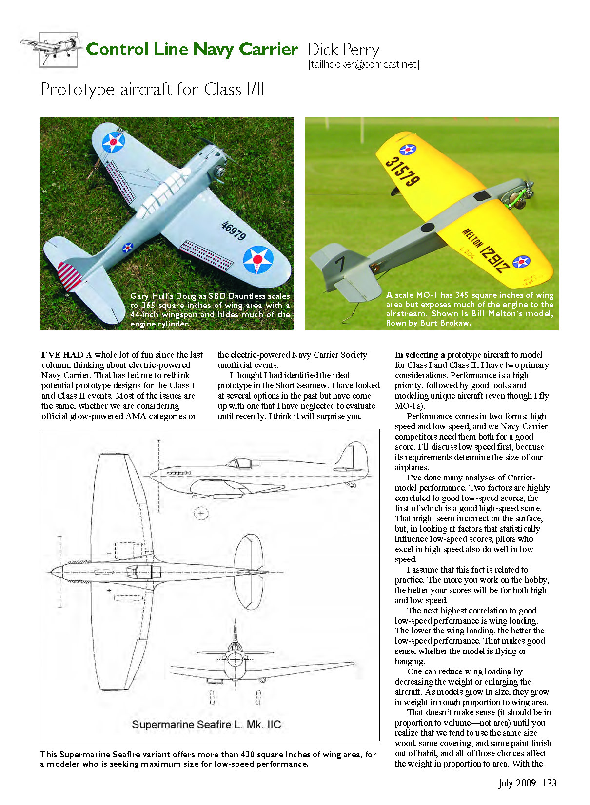
In selecting a prototype aircraft to model for Class I and Class II, I have two primary considerations: performance is the highest priority, followed by good looks and modeling unique aircraft (even though I fly MO-1s).
Performance comes in two forms: high speed and low speed, and we Navy Carrier competitors need them both for a good score. I'll discuss low speed first, because its requirements determine the size of our airplanes.
I've done many analyses of carrier-model performance. Two factors are highly correlated to good low-speed scores. The first of these is a good high-speed score. That might seem incorrect on the surface, but in looking at factors that statistically influence low-speed scores, pilots who excel in high speed also do well in low speed. I assume this fact is related to practice — the more you work on the hobby, the better your scores will be for both high and low speed.
The next highest correlation to good low-speed performance is wing loading. The lower the wing loading, the better the low-speed performance. That makes good sense, whether the model is flying or hanging.
One can reduce wing loading by decreasing the weight or enlarging the aircraft. As models grow in size they also grow in weight in rough proportion to wing area. That doesn't make sense (it should be in proportion to volume — not area) until you realize that we tend to use the same size wood, same covering, and same paint finish out of habit, and all of those choices affect the weight in proportion to area. With the weight of the engine, fuel system, control system, and landing gear relatively constant, bigger models produce lighter wing loadings. For that reason, for optimum low-speed performance an airplane should have a 44-inch wingspan. That will be the assumption for the high-speed discussion.
High speed depends on reducing drag. I recognize that the engine is a major factor in high-speed performance, but I'm discussing model design. Drag reduction depends primarily on a couple of factors related to the airplane's design. Appropriate airfoil and angle-of-attack distribution for the wing, which I've written about in the past, is not strongly related to the prototype design. However, profile drag is strongly influenced by the prototype.
There are three primary contributors to the drag of the model's nonlifting parts: fuselage cross-section, fuselage shape, and engine drag. Fuselage drag from cross-section is relatively straightforward: the bigger the fuselage cross-section, the higher the drag for a given shape. The shape of the fuselage influences drag by increasing or reducing airflow separation. Radial-engine prototypes, with their big, round cowls, can be a drag (literally) if they are designed poorly, but proper internal design, spinners, etc., can eliminate much of the disadvantage. The primary drag producer on our aircraft is the engine. A relatively large (in comparison to the fuselage) cylinder sticking out in the breeze is the culprit. A prototype's sleek nose can be completely dominated by the drag of the engine if it is left exposed. A radial-engine cowl can produce less total drag if it encloses more of the engine.
Let's look at the most popular Navy Carrier model: the MO-1. In fuselage cross-section it comes out ahead of all prototypes I can think of. Those of us who try to squeeze control systems and fuel tanks into MO-1s can attest to that.
The next best prototype is the Short Seamew; that's why I like it so much. The Seamew is only approximately 30% larger in cross-section than the MO-1.
Other prototypes that fare well in the fuselage-cross-section department are the standard Supermarine Seafire at about 40% larger and the Curtiss SO3C Seamew (there's something about that name) at about 65% larger. Most radial-engine prototypes come out at roughly double the MO-1.
The MO-1 is a big loser in fuselage shape, with its box cross-section and relatively sharp edges. It also loses big on engine exposure. With a large Class II engine, the crankcase even sticks out on the inboard side!
That's where the Seamew shines, with the entire engine blending in smoothly to the fuselage behind it (with a vertically mounted engine). The Seafire hides another 0.6 inch of engine cylinder compared to the MO-1, and the other Seamew (the Curtiss) can hide the whole engine if you're willing to accept an inverted installation.
Where does all this leave us in terms of prototype aircraft? If bigger is better for low-speed performance, larger wing area is a desirable feature.
Assuming that all models are built to scale with a 44-inch wingspan, the MO-1 standard comes out at 345 square inches of wing area, which beats many prototypes but is far from the best. The Short Seamew produces 380 square inches. The Curtiss Seamew comes in at 393 square inches. The Vought OS2U Kingfisher squares out at 410.
Most of the usual suspects beat the MO-1, coming in between 350 and 370 square inches, but you need to check each potential design. The standard Supermarine Seafire, which I mentioned earlier, is slightly smaller at 348 square inches.
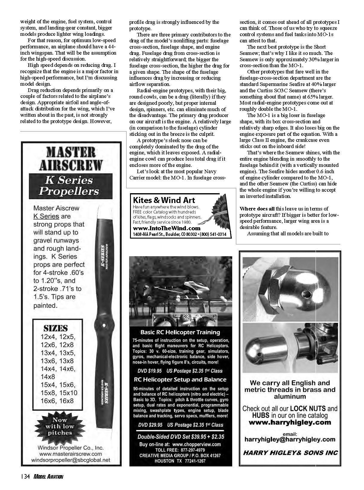
The biggest model I found in terms of wing area comes out at more than 430 square inches. The real surprise was that this prototype was the Supermarine Seafire! How can this be? The British did numerous things to the Seafire and Spitfire designs, including changing wingtip design to try to get better high- and low-altitude performance.
The Seafire L Mk IIC was derived from the Spitfire VC. The "L" designation indicates that it was intended for low-level operations. The L also means that the wingspan was reduced from 36 feet 10 inches to 32 feet 2 inches. That reduction, along with the loss of the relatively small wingtips (removed to achieve the span reduction), produces an increase in wing area of 85 square inches if both models are built to a 44-inch wingspan.
I hope to see many of you at the CL Navy Carrier Nats, which will be held July 7–10 at the International Aeromodeling Center in Muncie, Indiana. Those who can't make it can follow the action in the NatsNews newsletter on the AMA website. MA
Sources
- Seafire L. Mk II: http://en.wikipedia.org/wiki/Supermarine_Seafire
- Glenn L. Martin MO-1: http://en.wikipedia.org/wiki/Martin_MO-1
- Curtiss SO3C Seamew: http://en.wikipedia.org/wiki/SO3C_Seamew
- Vought OS2U Kingfisher: http://en.wikipedia.org/wiki/Vought_OS2U_Kingfisher
- Navy Carrier Society: http://cllflyer.tripod.com/ncs/ncs.htm
Transcribed from original scans by AI. Minor OCR errors may remain.

