
Control Line Precision Aerobatics
Author
Bob Hunt [email protected]
Finish your model professionally, in a fraction of the time, with soft carbon mat.
Introduction
We left off last time with Project Hole Shot, the fuselage essentially ready to accept the wing and tail group.
Unlike a built-up-fuselage airplane, profile models require no additional woodwork after the wing and tail group are installed. This gives us a chance to apply a good deal of the finish before the model gets "complicated" and harder to work on.
Getting into the nooks and crannies around the wing and tail assemblies, and achieving a smooth finish at those junctions, can be a pain. By applying some of the finish to the fuselage beforehand, the final finish can look more professional and be applied in a fraction of the normal time.
How much finish — and why do it now?
How much finish can be applied to the fuselage at this point? Quite a bit, actually. Applied now, the finish does more than make the airplane look pretty: it helps increase torsional rigidity and protects the balsa.
By nature, profile-fuselage models do not have a great deal of torsional rigidity. They are fast to build and offer ease of repair for those learning to fly, but they give up the more solid wing-and-tail mounting afforded by built-up fuselages.
Five elements of a good-flying Precision (Stunt) model
I have always believed that five elements add up to a good-flying Precision Aerobatics (Stunt) model:
- It must be light.
- It must be perfectly aligned (accurately assembled).
- It must be rigid.
- It must be equipped with a strong-running, reliable, easily tunable, consistent power package (engine, tank, and propeller).
- It must have a smooth-acting, precisely aligned, strong, long-lasting control system.
If any of the preceding elements is missing, the result is merely a caricature of a real Stunt model. That's harsh, but it's true.
Alignment and rigidity work hand in hand: a model that is accurately aligned on the bench but does not maintain that alignment under flight loads is effectively inaccurate. If the wing and tail are allowed to get out of alignment with each other while maneuvering, strange things can occur and the model cannot be used as an effective tool for learning Stunt.
Therefore, it is vital to make the fuselage as rigid as possible without adding too much weight. To regain a large portion of the inherent low torsional (twist) resistance of the profile fuselage, I highly recommend covering it at this point with 0.2-ounce (two-tenths of an ounce) carbon mat. It is easy to apply, and once in place—and the attachment medium has fully dried or cured—it adds measurably to the fuselage's strength and torsional resistance.
Carbon mat: experience and sources
We've come to a point where traditional model-building wisdom meets new materials. I've been covering all my models—built-up fuselage and profile types—with carbon mat (sometimes referred to as carbon 'veil') for years. The result has been amazingly rigid airplanes that maintain good flying qualities even when the wind starts to blow hard. Even built-up-fuselage models can begin to twist significantly in heavy wind, and the carbon mat helps resist that twist.
The carbon mat I use comes from Aerospace Composite Products (also referred to as Aerospace Composites), but other sources sell similar material. Early on there were two types of carbon mat: one had a "sizing" applied to make the mat somewhat stiffer and easier to roll and handle; the other had no sizing. The unsized mat is extraordinarily flimsy and difficult to roll, while the sized mat is stiffer.
For our purposes it is imperative to obtain the unsized carbon mat. Do not use carbon mat that has been treated with a sizing or stiffening substance.
Why not use the sized mat? The sizing prevents the material from forming easily around compound curves when covering a model. Worse, the sizing tends to develop pinhole voids during sanding after initial application: some areas sand away more readily than others, leaving an inconsistent surface and resulting in pinholes in the finish.
I experienced this problem early on and switched to the unsized mat. I've had no pinhole problems since. The people at Aerospace Composite Products were made aware of the issue and ceased providing the sized mat; they call the unsized material "Soft Carbon Mat." When you order it, specify "Soft Carbon" (or otherwise explicitly request unsized material).
Application steps
Applying the carbon mat is easy, but follow these steps to achieve the desired result:
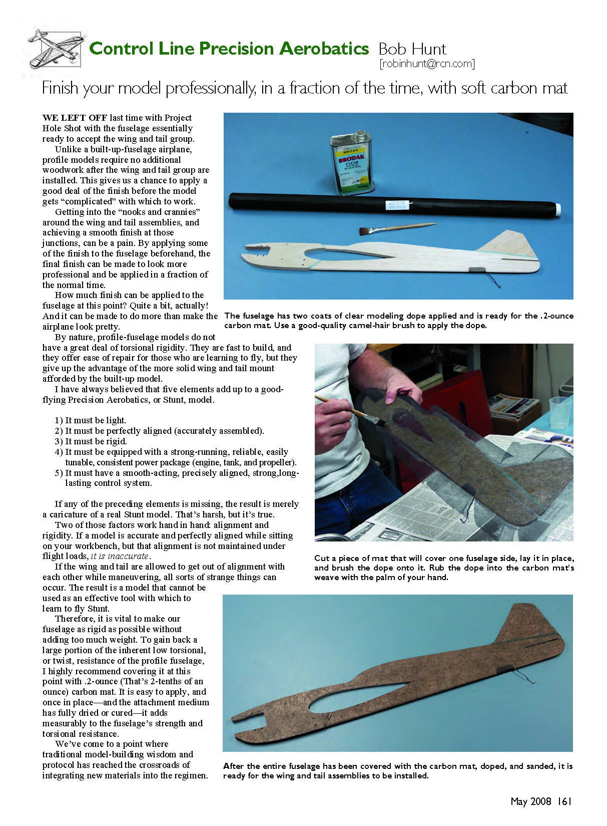
- Brush two or three coats of clear dope onto the airframe (the fuselage in this case). Apply enough coats to give the surface a satin sheen. Allow these coats to dry sufficiently before proceeding.
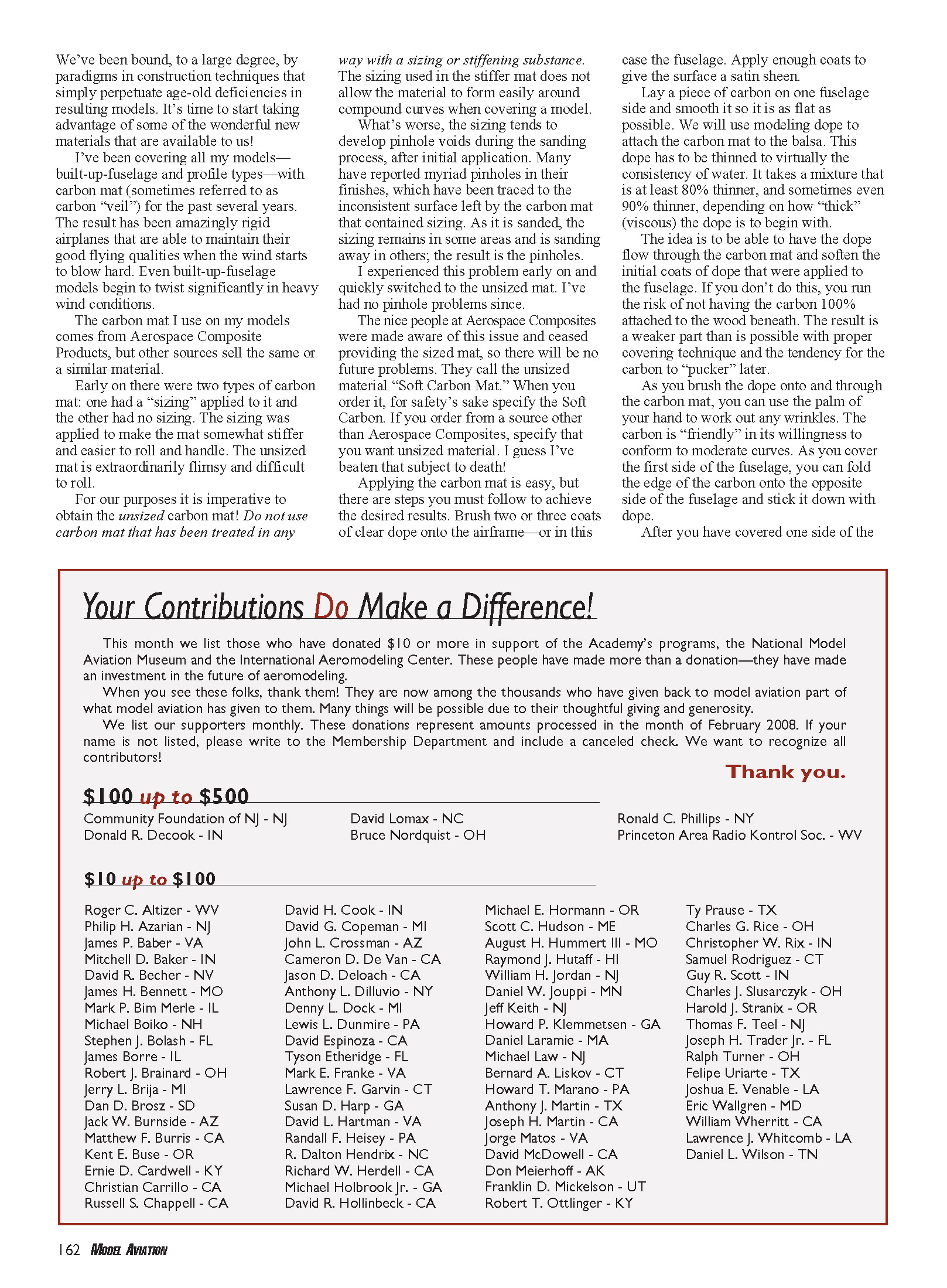
- Lay a piece of carbon mat on one fuselage side and smooth it so it is as flat as possible.
- Use modeling dope to attach the carbon mat to the balsa. The dope has to be thinned to virtually the consistency of water: use at least an 80% thinner mix, and sometimes up to a 90% thinner mix, depending on the original viscosity of the dope. The goal is for the dope to flow through the carbon mat and soften the initial coats applied to the fuselage so the mat bonds 100% to the wood beneath.
- If you do not thin the dope enough, you risk incomplete adhesion and later puckering of the carbon.
- As you brush the thinned dope onto and through the carbon mat, you can use the palm of your hand to work out any wrinkles. The unsized carbon conforms well to moderate curves.
- As you cover the first side of the fuselage, fold the edge of the carbon onto the opposite side and tack it down with dope.
After you have covered one side of the fuselage, cover the other side in the same manner. Allow the attachment medium to fully dry or cure; once cured, the carbon mat will have added torsional rigidity and durability to the fuselage. Finish-sand and apply your final finish coats as desired.
Transcribed from original scans by AI. Minor OCR errors may remain.

