
CONTROL LINE RACING - 2003/04
Dave McDonald, Box 384, Daleville IN 47334; E-mail: [email protected]
As the flying season approaches, and is probably well underway in parts of the country, I hope we have all decided to build that .15 Rat. You may recall that in the last column I included the rules for the event. I hope you have decided to join us in the Rat circle.
The debate on airplane type and configuration has filled most conversations in the past few months. Which wing will be best — upright, inverted, or the F2C type? Right now the answer is unknown. What is known is that each airplane has its benefits and drawbacks.
While easier to build, upright designs have the problem of getting a fuel-filling mechanism around a minipipe. Most uprights tend to be slightly slower, and they tend to require a little down-trim on takeoff because of the angle at which they sit due to the long landing gear. If the upright is built using a side-exhaust engine, the problem with the fuel filler is a nonissue. Uprights will probably not draw in as much dirt as an invert.
Although probably faster, the inverted type has potential for starting problems since most engines are of the front-intake variety. Will the air coming off the propeller combined with the open venturi act as a big vacuum cleaner and draw dirt and other items into the venturi, causing potential engine damage? A filter or screen over the venturi opening might be necessary if you are going to run the inverted design.
The F2C wing type is clean in design, but will probably suffer from poor shutdown characteristics. This design will need a full-length, or double, elevator because the traditional elevator may not provide adequate maneuverability during shutdown; this will require at least a full lap to bring the airplane safely into the pits.
What will the speeds be? I think a good .15 Rat should run roughly 13 seconds for seven laps, but that is only speculation at this time; the development of the airplanes is not that far along.
What propeller will be best? Length? Pitch? I think 6.100 x 6.000 inches would be a good starting point; an upright may not work as well on the same propeller as an invert, and the invert may not work as well as the F2C wing type. Propeller selection will require many test sessions to see what the engines like and what they dislike.
Will heat be a problem? For some it will be, and for others it probably won't. Attention to cooling and the ability to control cooling may become more important in this event than most might think.
How much fuel should a .15 Rat carry? I think 2.5 ounces is the magic number; that should provide more than adequate range, yet be small enough to get into each design airplane.
Since .15 Rat will put the minipipe back in Control Line (CL) Racing, I am working on some carbon-fiber minipipes. Will these work any better than aluminum ones? I don't know, but I do know that I will be able to work with various sizes by turning out different-size plugs. By the time this column is in your hands, I hope to have tested various sizes and lengths of minipipes on different propellers to achieve a performance baseline. Will different weather conditions affect minipipe selection? I don't believe so, but a selection of sizes may become useful.
Leadout Guides:
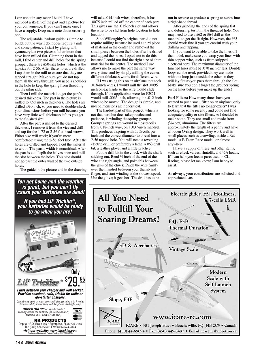
A useful and much-overlooked piece of equipment on any CL racer is the leadout guide. I put a small, efficient adjustable leadout guide in all my new airplanes. This guide was Stoo Willoughby's concept. I changed the design's construction method and dimensions, and now I can use it in any racer I build. I have included a sketch of the part and a picture for your convenience. If you can't make one, I have a supply. Drop me a note about ordering.
The adjustable leadout guide is simple to build, but the way I do it does require a mill and some patience. I start by gluing with cyanoacrylate two pieces of aluminum that have been milled flat. Clamping them in the mill, I find center and drill holes for the grouper spring; these are #50-size holes, which is the tap size for 2-56. After these holes are drilled, I tap them in the mill to ensure that they are tapped straight. Make sure you do not tap them all the way through; you need a shoulder in the hole to keep the spring from threading out the other side.
Then I mill the material to get the part's desired thickness. The part in the picture is milled to 0.095 inch in thickness. The holes are drilled 0.070 inch, so you need to double-check your dimensions before you mill because you have very little wall thickness left as you get to the finished size.
After the part is milled to the desired thickness, I remove it from the vice and drill and tap for 1-72 or 2-56 flat-head screws. Either size will work; if you're more comfortable using 2-56, feel free. After the holes are drilled and tapped, I cut the material to width. The part's width is noncritical. After the part is cut, I split the halves open and mill the slot between the holes. This slot should not go past the outer wall of the two outside holes.
The guide in the picture and in the drawing will take 0.014-inch wires; therefore, it has 0.0075 inch milled off the center of each part. This gives a 0.015-inch slot and allows the wire to be slid from hole location to hole location.
Stoo Willoughby's original part did not require milling because he used a third piece of material in the center and removed the small pieces between the holes after he drilled and tapped the holes. I opted not to do this because I could not find the right size of shim material for the center. The method I used allows me to make the part the same way every time, and by simply milling the center, different thicknesses work for different wire.
If I were using this on an airplane that took 0.018-inch wires, I would mill the slot 0.0095 inch on each side so the wire would slide through. If the application were for F2C I would mill 0.0065 inch, allowing the 0.012-inch wires to be moved. The design is simple, and most dimensions are noncritical.
The hardest part of this project, which is not hard but does take practice and patience, is winding the grouper spring. Grouper springs are wound in closed coils from 0.018-inch wire, on a 0.037-inch mandrel. This produces a spring with about 55.5 coils per inch and the correct diameter to thread into a 2-56 tapped hole. You will need a reversing electric drill, or preferably a lathe, a #63 drill bit, a leather glove, and a little practice.
Tools and materials for winding the spring:
- Reversing electric drill or lathe
- #63 drill bit
- 0.037-inch mandrel
- 0.018-inch wire
- Leather glove
Put the drill bit in the chuck with the shank sticking out. Bend 1/2 inch of the end of the wire at a right angle, and poke this between the jaws of the chuck. Pinch the wire firmly over the mandrel between your thumb and finger, and start winding at the slowest speed. Use the glove; it gets hot! The drill has to be run in reverse to produce a spring to screw into a right-hand thread.
After grinding the ends of the spring flat and deburring, test it in the threaded hole. You may need to use a #62 or #64 drill as the mandrel to get the fit right. However, the #63 should work fine if you are careful with your drilling and tapping.
If you want to be able to take the lines off the model, make sure you wrap your lines with thin copper wire, such as from stripped electrical cord. The maximum diameter of the finished lines must be 0.070 inch or less. Double loops can be used, provided they are made with one loop just outside the other so they will lay flat as you pass them through the slot. Make sure you don't forget the grouper spring on the lines before you make up the ends!
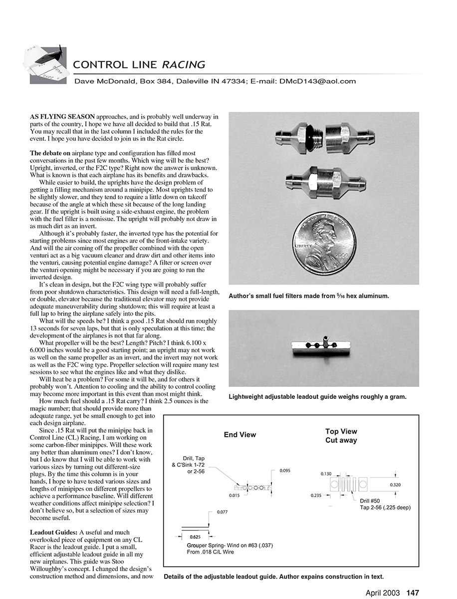
Fuel Filters:
How many times have you wanted to put a small filter on an airplane, only to learn that the filter no longer exists? I was looking for some recently and could not find adequate quality or size filters, so I decided to make some. They are small and made from 5/16-inch hex aluminum. The filters are approximately the length of a penny and have a hidden O-ring design. They work well in small places such as a cowling, inside a Rat model, a B Team Race model, or almost anywhere.
I have a supply of these and other items, such as check valves, shutoffs, and 1/2A heads. If I can help you locate parts used in CL racing, please let me know; I am happy to assist.
As always, your contributions are solicited and appreciated.
MA
Transcribed from original scans by AI. Minor OCR errors may remain.

