
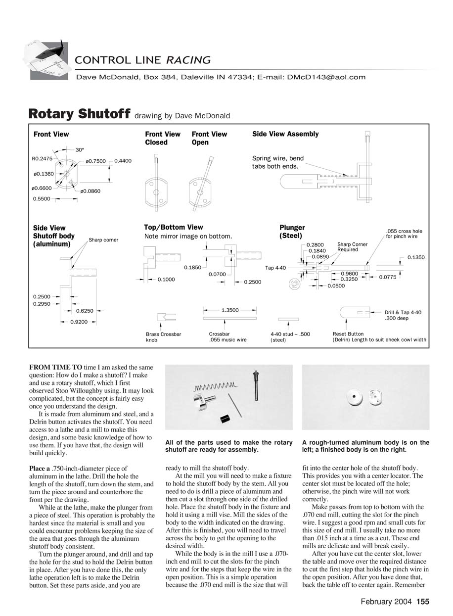
Rotary Shutoff — drawing by Dave McDonald
FROM TIME TO time I am asked the same question: How do I make a shutoff? I make and use a rotary shutoff, which I first observed Stoo Willoughby using. It may look complicated, but the concept is fairly easy once you understand the design.
It is made from aluminum and steel, and a Delrin button activates the shutoff. You need access to a lathe and a mill to make this design, and some basic knowledge of how to use them. If you have that, the design will build quickly.
Materials and tools
- Aluminum stock, .750-inch diameter for the shutoff body
- Steel for the plunger
- Delrin for the button
- Pinch wire, .055 inch diameter (recommended)
- Spring (MSC part number 03307956)
- 2-56 flat-head machine screws for mounting (recommended)
- 4-40 stud for the button
- Drill bits: No. 63 and others as indicated
- End mill: .070-inch for slots
- Lathe and mill (a drill press can be used for some drilling if you make a fixture)
- Cyanoacrylate glue, epoxy
- Small brass inserts (tapped 2-56) for mounting into hardwood
Lathe operations
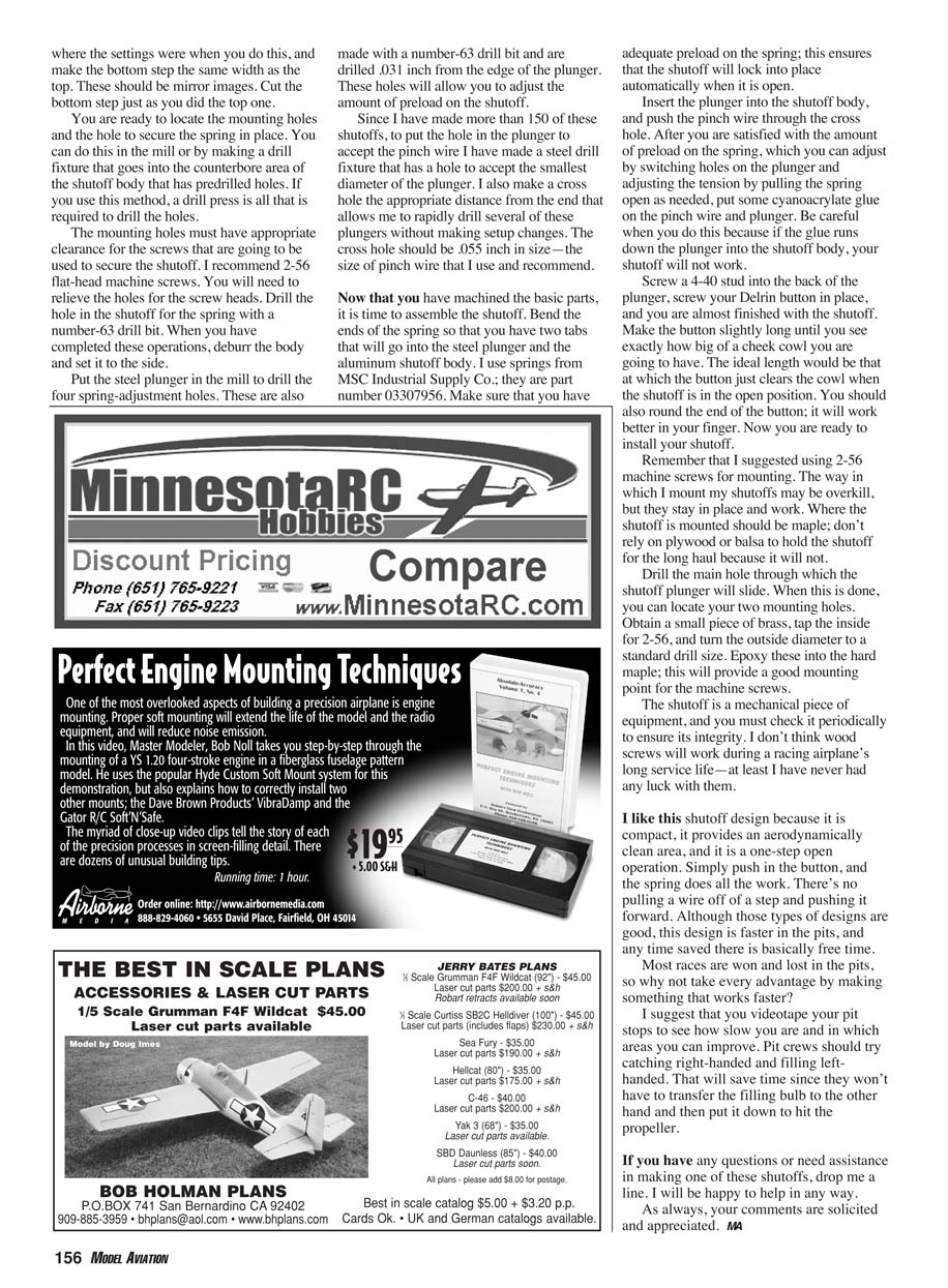
- Place a .750-inch-diameter piece of aluminum in the lathe.
- Drill the center hole the length of the shutoff.
- Turn down the stem.
- Turn the piece around and counterbore the front per the drawing.
- Make the plunger from a piece of steel. This is the hardest operation because the material is small and keeping the area that goes through the aluminum body consistent can be difficult.
- Turn the plunger around and drill and tap the hole for the stud that holds the Delrin button.
- Make the Delrin button on the lathe. Make the button slightly long initially — you will trim it to fit the cheek cowl later. Round the end for better fingertip operation.
Set these parts aside when finished.
Fixture for milling
- Make a fixture to hold the shutoff body by the stem: drill a piece of aluminum and cut a slot through one side of the drilled hole.
- Place the shutoff body in the fixture and secure it in the mill vise.
Milling operations
- Mill the sides of the body to the width indicated on the drawing.
- Travel across the body to get the opening to the desired width.
- Use a .070-inch end mill to cut the slots for the pinch wire and for the steps that keep the wire in the open position. The .070 end mill fits into the center hole of the shutoff body and provides a center locator.
- The center slot must be located off the hole; otherwise, the pinch wire will not work correctly.
- Make passes from top to bottom with the .070 end mill, cutting the slot for the pinch wire.
- Use a good RPM and small cuts for this size of end mill; I usually take no more than .015 inch per pass. These end mills are delicate and will break easily.
- After cutting the center slot, lower the table and move over the required distance to cut the first step that holds the pinch wire in the open position.
- Back the table off to center again and make the bottom step the same width as the top (mirror images). Cut the bottom step the same way as the top one.
Drilling and finishing
- Locate and drill the mounting holes and the hole to secure the spring. This can be done in the mill or by making a drill fixture that fits into the counterbore area of the shutoff body with predrilled holes; if you use the fixture, a drill press is all that is required.
- The mounting holes must have appropriate clearance for the screws you will use (2-56 flat-head machine screws recommended). Relieve the holes for the screw heads.
- Drill the hole in the shutoff for the spring with a No. 63 drill bit.
- Deburr the body and set it aside.
Plunger drilling and pinch wire hole
- Put the steel plunger in the mill to drill the four spring-adjustment holes with a No. 63 drill bit. Drill these holes .031 inch from the edge of the plunger. These holes allow you to adjust the amount of preload on the shutoff.
- To make the pinch wire hole in the plunger efficiently, make a steel drill fixture that has:
- A hole to accept the smallest diameter of the plunger
- A cross hole at the correct distance from the end
- The cross hole size should be .055 inch (the size of the pinch wire recommended).
Assembly
- Bend the ends of the spring so you have two tabs that will go into the steel plunger and the aluminum shutoff body. Use the spring (MSC part number 03307956) or an equivalent.
- Ensure adequate preload on the spring so the shutoff will lock automatically when it is open.
- Insert the plunger into the shutoff body and push the pinch wire through the cross hole.
- Adjust preload by selecting different holes on the plunger and by pulling the spring open as needed.
- Once satisfied, put some cyanoacrylate glue on the pinch wire and plunger to secure them. Be careful not to let glue run down the plunger into the shutoff body, or the shutoff will not work.
- Screw a 4-40 stud into the back of the plunger and screw your Delrin button in place. Trim the button to the ideal length so it just clears the cheek cowl when the shutoff is in the open position.
Mounting the shutoff
- I recommend mounting the shutoff into hardwood (maple). Do not rely on plywood or balsa for long-term durability.
- Drill the main hole through which the shutoff plunger will slide. Locate the two mounting holes.
- Obtain a small piece of brass, tap the inside for 2-56, and turn the outside diameter to a standard drill size. Epoxy these brass inserts into the maple to provide a good mounting point for the machine screws.
- I believe wood screws are inadequate for a racing airplane's long service life; machine screws into brass inserts in hardwood provide a durable mounting.
Performance and advantages
- This shutoff design is compact, provides an aerodynamically clean area, and is a one-step open operation: push the button and the spring does the work.
- Compared with designs that require pulling a wire off a step and then pushing forward, this design is faster in the pits — and any time saved there is essentially free time.
- Most races are won and lost in the pits, so take every advantage by making something that works faster.
Pit tips
- Videotape your pit stops to see how slow you are and where you can improve.
- Pit crews should practice catching right-handed and filling left-handed. That saves time because they won't have to transfer the filling bulb to the other hand and then put it down to hit the propeller.
If you have any questions or need assistance in making one of these shutoffs, drop me a line. I will be happy to help in any way.
As always, your comments are solicited and appreciated.
MA
Transcribed from original scans by AI. Minor OCR errors may remain.

