
CONTROL LINE RACING
Dave McDonald
Box 384, Daleville IN 47334 E-mail: [email protected]
CL racing has experienced some great advancements through the years. The Nelson engine has replaced almost every other type, and if you want to win, you use the best technology.
Dick Lambert has always been a leader in using the best technology and getting the most from his models, so his new F2C project is no surprise. Approximately two years ago Dick decided that the current F2C wing technology could be improved. After seeing some carbon-fiber wings, he decided it was time to advance the technology curve in F2C.
Carbon wing development
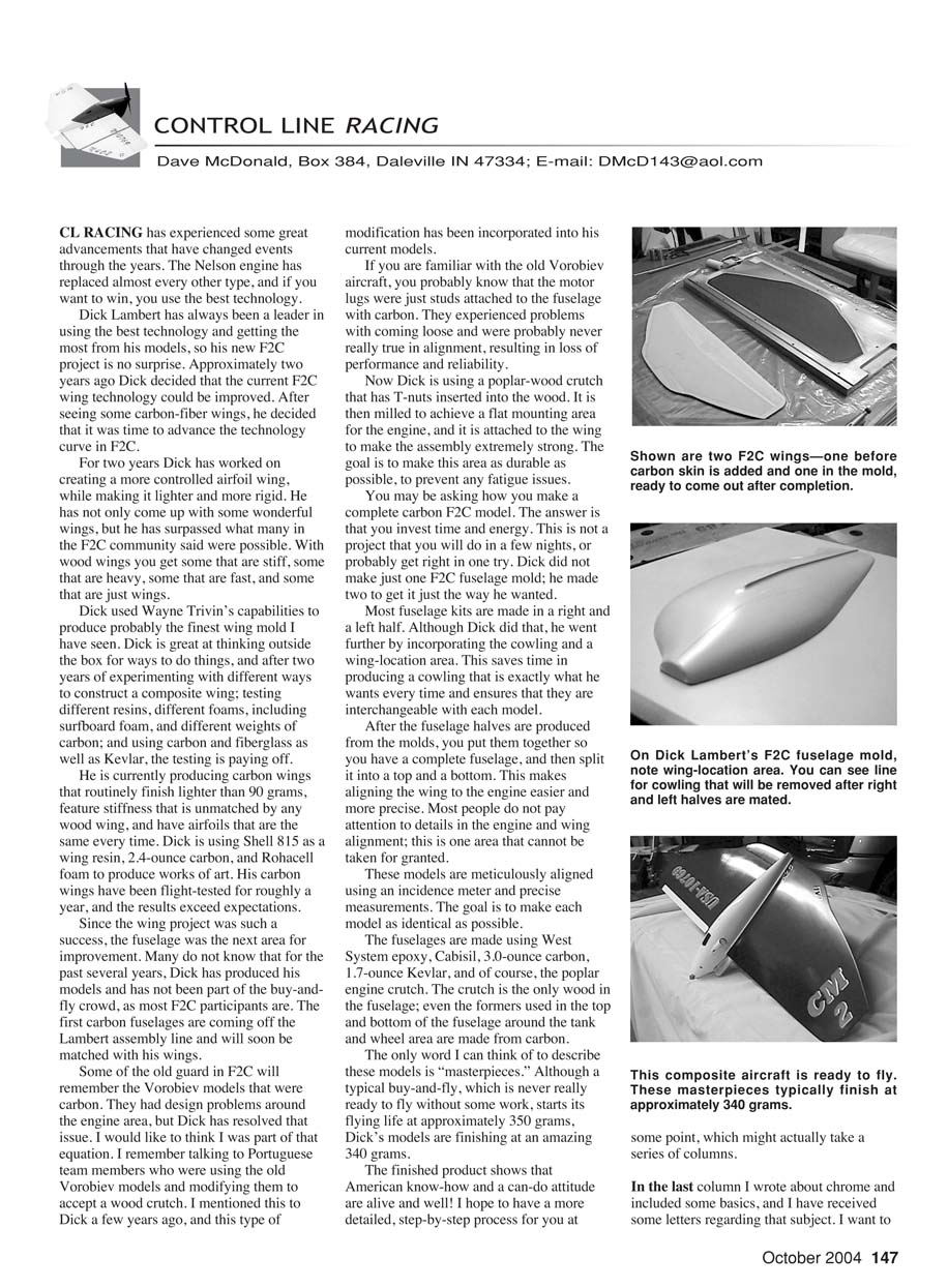
For two years Dick worked on creating a more controlled airfoil wing while making it lighter and more rigid. He has not only come up with some wonderful wings, but he has surpassed what many in the F2C community said were possible. With wood wings you get some that are stiff, some that are heavy, some that are fast, and some that are just wings. Dick used Wayne Trivin's capabilities to produce probably the finest wing mold I have seen.
Dick thinks outside the box. After two years of experimenting with different ways to construct a composite wing—testing different resins, different foams (including surfboard foam), different weights of carbon, and combinations of carbon, fiberglass, and Kevlar—the testing is paying off. His carbon wings have been flight-tested for roughly a year, and the results exceed expectations.
Features of Dick’s carbon wings:
- Routinely finish lighter than 90 grams.
- Stiffness unmatched by any wood wing.
- Consistent airfoils, identical every time.
- Materials and resin used include Shell 815, 2.4-ounce carbon, and Rohacell foam.
Fuselage development
Since the wing project was such a success, the fuselage was the next area for improvement. Many do not know that for the past several years Dick has produced his models and has not been part of the buy-and-fly crowd, as most F2C participants are. The first carbon fuselages are coming off the Lambert assembly line and will soon be matched with his wings.
Some of the old guard in F2C will remember the Vorobiev models that were carbon. They had design problems around the engine area, but Dick has resolved those issues. I like to think I was part of that equation: I remember talking to Portuguese team members who were using the old Vorobiev models and modifying them to accept a wood crutch. I mentioned this to Dick a few years ago, and this type of modification has been incorporated into his current models.
If you are familiar with the old Vorobiev aircraft, you probably know that the motor lugs were just studs attached to the fuselage with carbon. They tended to come loose and were probably never true in alignment, resulting in loss of performance and reliability. Now Dick uses a poplar-wood crutch with T-nuts inserted. The crutch is milled to achieve a flat mounting area for the engine and is attached to the wing to make the assembly extremely strong. The goal is to make this area as durable as possible to prevent any fatigue issues.
Fuselage materials and construction process
The only wood in the fuselage is the poplar engine crutch. The rest is composite. Materials used include:
- West System epoxy
- Cabosil (fumed silica)
- 3.0-ounce carbon
- 1.7-ounce Kevlar
- Poplar engine crutch (with T-nuts)
- Carbon formers for tank and wheel areas
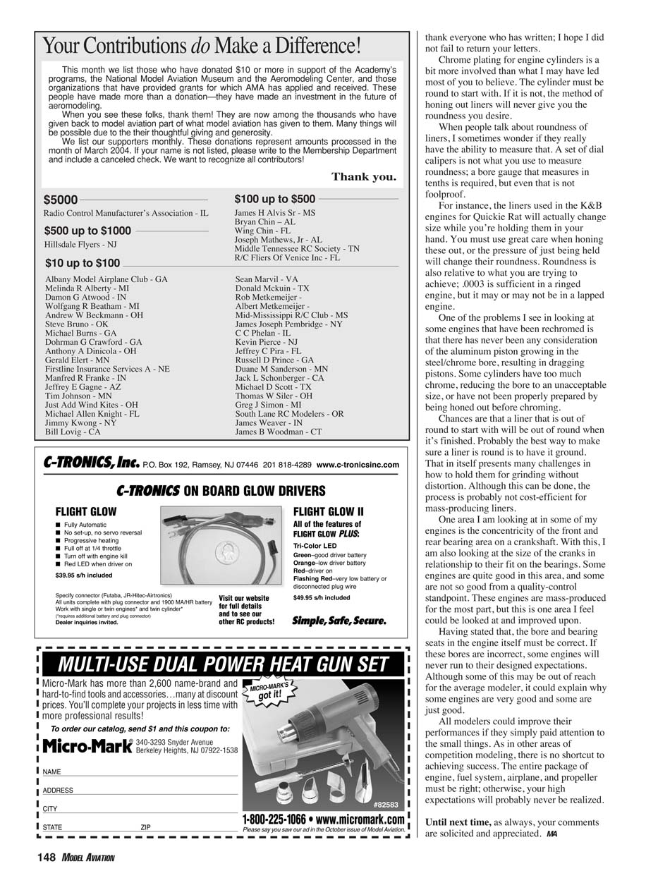
Dick did not make just one F2C fuselage mold; he made two to get it just the way he wanted. Most fuselage kits are made in a right and left half. Although Dick did that, he went further by incorporating the cowling and a wing-location area. This saves time producing a cowling that is exactly what he wants every time and ensures interchangeability between models.
Typical fuselage assembly steps:
- Produce right and left fuselage halves from the molds (including cowling and wing-location features).
- Join the halves to create a complete fuselage.
- Split the complete fuselage into a top and a bottom to make aligning the wing to the engine easier and more precise.
- Meticulously align the model using an incidence meter and precise measurements so each model is as identical as possible.
A typical buy-and-fly model often begins its flying life at approximately 350 grams; Dick's finished models are an amazing 340 grams.
The finished product shows that American know-how and a can-do attitude are alive and well. I hope to have a more detailed, step-by-step process for you at some point, which might actually take a series of columns.
Chrome plating and cylinder roundness
In the last column I wrote about chrome and included some basics, and I have received several letters regarding that subject. I want to thank everyone who has written; I hope I did not fail to return your letters.
Chrome plating for engine cylinders is more involved than some may believe. The cylinder must be round to start with. If it is not, the method of honing out liners will never give you the roundness you desire.
When people talk about roundness of liners, I sometimes wonder if they really have the ability to measure that. A set of dial calipers is not what you use to measure roundness; a bore gauge that measures in tenths is required, but even that is not foolproof.
For instance, the liners used in the K&B engines for Quickie Rat will actually change size while you’re holding them in your hand. You must use great care when honing these out, or the pressure of just being held will change their roundness. Roundness is also relative to what you are trying to achieve; .0003" is sufficient in a ringed engine, but it may or may not be in a lapped engine.
One problem I see in some rechromed engines is that there has never been any consideration of the aluminum piston growing in the steel/chrome bore, resulting in dragging pistons. Some cylinders have too much chrome, reducing the bore to an unacceptable size, or have not been properly prepared by being honed out before chroming. Chances are that a liner that is out of round to start with will be out of round when finished. Probably the best way to make sure a liner is round is to have it ground. That presents challenges in how to hold them for grinding without distortion, and although it can be done, the process is probably not cost-efficient for mass production.
Bearings, crankshafts, and overall quality
One area I am looking at in some of my engines is the concentricity of the front and rear bearing areas on a crankshaft. I am also looking at the size of the cranks in relationship to their fit on the bearings. Some engines are quite good in this area, and some are not so good from a quality-control standpoint. These engines are mass-produced for the most part, but this is one area that could be improved.
The bore and bearing seats in the engine itself must be correct. If these bores are incorrect, some engines will never run to their designed expectations. Although some of this may be out of reach for the average modeler, it could explain why some engines are very good and some are just good.
All modelers could improve their performances if they simply paid attention to the small things. As in other areas of competition modeling, there is no shortcut to achieving success. The entire package of engine, fuel system, airplane, and propeller must be right; otherwise your high expectations will probably never be realized.
Until next time, as always, your comments are solicited and appreciated.
MA
Transcribed from original scans by AI. Minor OCR errors may remain.

