
Control Line: Scale
Bill Boss
Control System
In my February 1985 column, I covered the general operation of the three-line control system and some of the possible difficulties that might be encountered if line lengths are not accurate, or if different manufacturers' parts are mixed and matched. At that time I did not talk in detail about the basic installation of the plane's control unit—and why a job well done in this area of the model's construction is important.
What brought this subject to mind was the extra amount of time and effort I spent recently installing the control system in my latest Scale project, a P-51 Mustang. I also wondered how many readers might be newcomers to Scale and might benefit from a few words on the subject. While what follows applies to a particular model, the principles can be applied to any model of your choosing.
Planning the installation
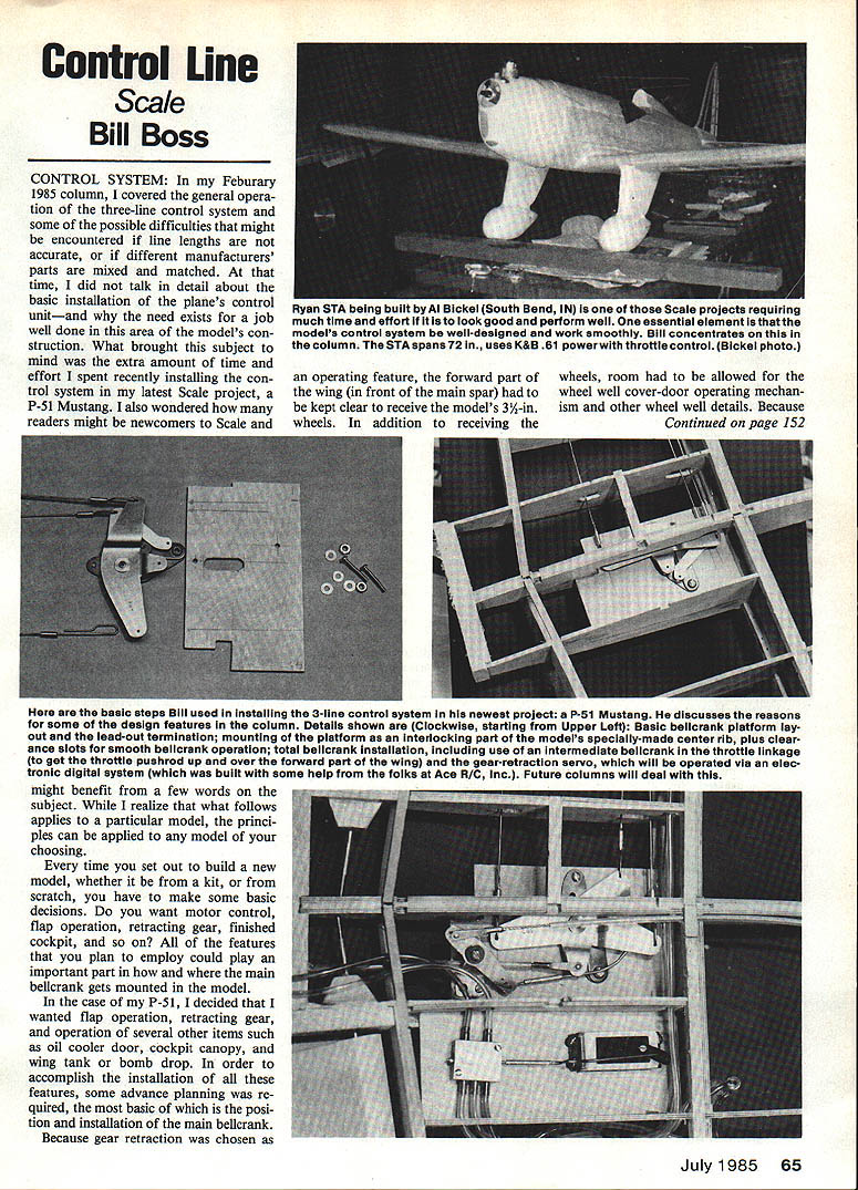
An operating feature forced one constraint on the installation: the forward part of the wing (in front of the main spar) had to be kept clear to receive the model's 3-1/2 in. wheels. In addition to receiving the wheels, room had to be allowed for the wheel-well cover-door operating mechanism and other wheel-well details.
Every time you set out to build a new model—whether from a kit or from scratch—you have to make some basic decisions:
- Do you want motor control?
- Will you have flap operation?
- Will you use retracting gear?
- Do you want a finished cockpit?
- What other scale features will you include (oil cooler door, canopy, wing tank or bomb drop, etc.)?
All of the features you plan to employ can affect how and where the main bellcrank gets mounted in the model.
Wing structure and center rib
In the case of my P-51, I decided I wanted flap operation, retracting gear, and operation of several other items such as oil cooler door, cockpit canopy, and wing tank or bomb drop. To accomplish the installation of all these features, some advance planning was required—most basically the position and installation of the main bellcrank.
Because gear retraction was chosen as one of the landing gear requirements, it was decided to use a single, specially made center wing rib as a base for the wheel-well cover doors and the main bellcrank mounting.
As is my usual practice when building from plans that were meant for RC use (in this case, plans by Bryan Taylor of Great Britain obtained from Bob Holman Plans, San Bernardino, CA), the wing's main spar and ribs—from the center to the point at which the landing gear will be mounted—are all made of 1/8-in. plywood. This is done to make as solid a base as possible on which to build the rest of the model. (See my August 1982 MA column for general information on converting RC kits to CL use.) In this case, in addition to making many of the ribs of plywood, the wing's center rib was constructed by laminating two 1/8-in. plywood ribs and one 1/8-in. balsa rib. It was specially slotted to accept the main bellcrank platform.
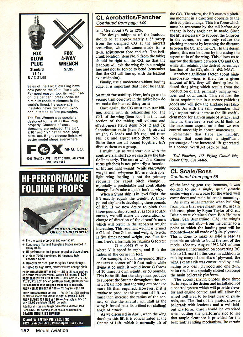
The accompanying photos show three basic steps in the design and installation of the center rib. Care should be exercised when cutting the platform's slot to ensure ample clearance is provided for the bellcrank's sliding mechanism. Be certain that no binding takes place throughout the bellcrank's operating range.
Bellcrank platform and leadouts
The leadouts are shown purposely with only two attached to the bellcrank so that a method of making leadout terminations (which I have used successfully for many years) could be shown. As you can see, an offset is put in the solid piano wire, and then carefully bent to form a loop that has an inside radius of about 1/16 in. The leadout is then threaded onto the bellcrank with the offset facing up, and a small piece of copper or brass tubing is moved into place and properly soldered.
When soldering this tubing in place, be sure the wire is clean and that the solder, when applied to one end of the tubing, flows through to the other end.
The wire used was .046-in. diameter and was chosen for two basic reasons. First, it was the largest size the bellcrank holes would accept without drilling. Secondly, the size fits a rule of my own that I generally follow when making up my model's control systems: the leadout size should be about twice the size of the lines required to fly the model in competition. This practice provides a large margin of safety for pull-testing and for control system wear.
Reinforcement and assembly
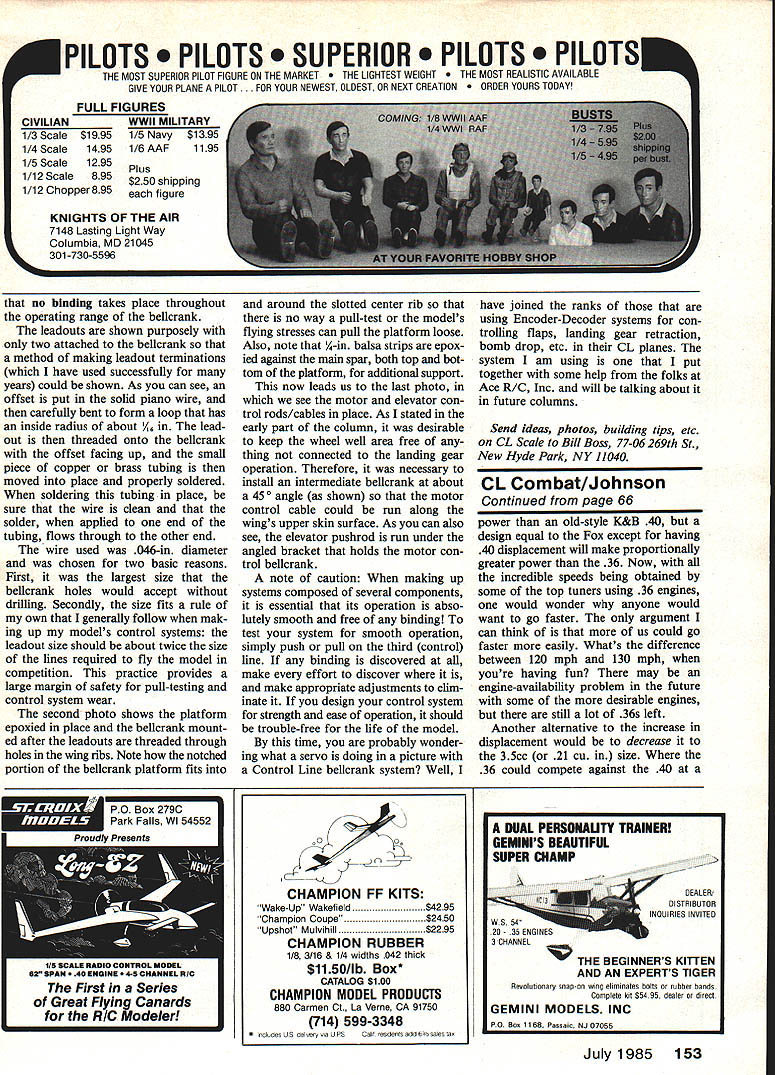
The second photo shows the platform epoxied in place and the bellcrank mounted after the leadouts are threaded through holes in the wing ribs. Note how the notched portion of the bellcrank platform fits into and around the slotted center rib so that there is no way a pull-test or the model's flying stresses can pull the platform loose. Also note that 1/8-in. balsa strips are epoxied against the main spar, both top and bottom of the platform, for additional support.
Motor and elevator control routing
This now leads us to the final photo, which shows the motor and elevator control rods/cables in place. As stated earlier, it was desirable to keep the wheel-well area free of anything not connected to the landing gear operation. Therefore it was necessary to install an intermediate bellcrank at about a 45° angle so that the motor control cable could be run along the wing's upper skin surface. The elevator pushrod is run under the angled bracket that holds the motor-control bellcrank.
Testing and caution
A note of caution: when making up systems composed of several components, it is essential that operation is absolutely smooth and free of any binding. To test your system for smooth operation, simply push or pull on the third (control) line. If any binding is discovered at all, make every effort to locate it and make appropriate adjustments to eliminate it. If you design your control system for strength and ease of operation, it should be trouble-free for the life of the model.
Encoder-decoder systems
By this time you are probably wondering what a servo is doing in a picture with a control line bellcrank system. Well, I have joined the ranks of those who are using encoder-decoder systems for controlling flaps, landing gear retraction, bomb drop, etc. in their CL planes. The system I am using is one that I put together with some help from the folks at Ace R/C, Inc., and I will be talking about it in future columns.
Send ideas, photos, building tips, etc. on CL Scale to: Bill Boss 77-06 269th St. New Hyde Park, NY 11040
Transcribed from original scans by AI. Minor OCR errors may remain.

