
Control Line: Scale
Bill Boss 77-06 246th Street New Hyde Park, NY 11040
HOW TO SET UP and operate an electronic control system for CL Scale models. Part Two is this month's topic. Last month I provided some basic information on the operation of a two-channel system used for flaps and gear retraction. So far I have covered the encoder, two types of input control devices and the wiring and assembly of a control box that can be attached to a three-line control handle.
This month I'll discuss the decoder and a modification that will permit it to accept the encoder output in order to properly operate the servos.
Decoder modification
The decoder used in this project is the digital proportional RX decoder from Ace R/C. (Last month's encoder board is also from Ace.) The decoder has an output for the operation of positive pulse servos and can be ordered either in kit form or as a factory-wired unit. The latter has wiring for seven channels, battery supply leads, and leads that would normally have been connected to the receiver section of an RC system. I chose the prewired version for this project since there would be less chance of wiring error and trouble.
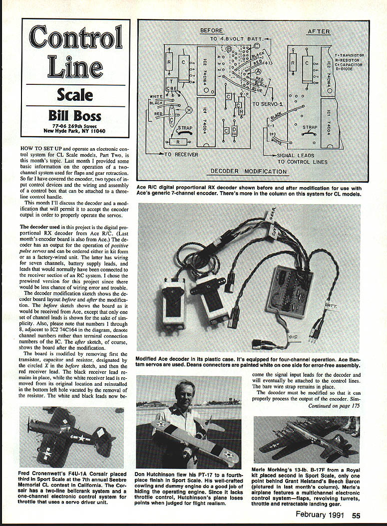
The decoder modification sketch shows the decoder board layout before and after the modification. The before sketch shows the board as it would be received from Ace, except that only one set of channel leads is shown for the sake of simplicity. Also note that numbers 1 through 8 adjacent to IC2 74C164 in the diagram denote channel numbers rather than terminal connection numbers of the IC. The after sketch, of course, shows the board after the modification.
The board is modified by first removing the transistor, capacitor and resistor designated by the circled X in the before sketch, and then removing the red receiver lead. The black receiver lead remains in place, while the white receiver lead is removed from its original location and reinstalled in the bottom-left hole vacated by the removal of the resistor. The white and black leads now become the signal input leads for the decoder and will eventually be attached to the control lines. The bare wire strap remains in place.
The decoder must be modified so that it can properly process the output of the encoder. Upon receiving these pulses, the modified decoder passes them through a series of inverters (contained in IC-1) and finally onto IC-2, which further processes and synchronizes the pulse train to provide the positive output pulse required to operate a servo. If we did not remove the transistor, the encoder output would pass through an extra stage. This would reverse the pulse polarity one time too many, and the servos would not operate.
Channel wiring
If the prewired decoder is used, all seven channels are wired. A close examination of the wiring will show that the output leads for channels 1, 3 and 4 (odd-colored wire) are grouped together and have a common set of red (+) and black (–) battery leads. This grouping was intended for termination in a Deans connector block while channels 2 and 4 through 7 would be terminated with individual female three-pin Deans connectors.
This wiring setup was intended for use with a receiver. We can use the same wiring arrangement if we wish to build a system with four or more working channels. If for some reason all channels were to be individually wired, red and black battery supply leads would have to be wired for channels 3 and 4. Spare holes for this purpose can be found in the dotted-line areas marked A and B. (The area marked C contains spare holes that are isolated from the rest of the circuitry and thus of no use to us in this project.)
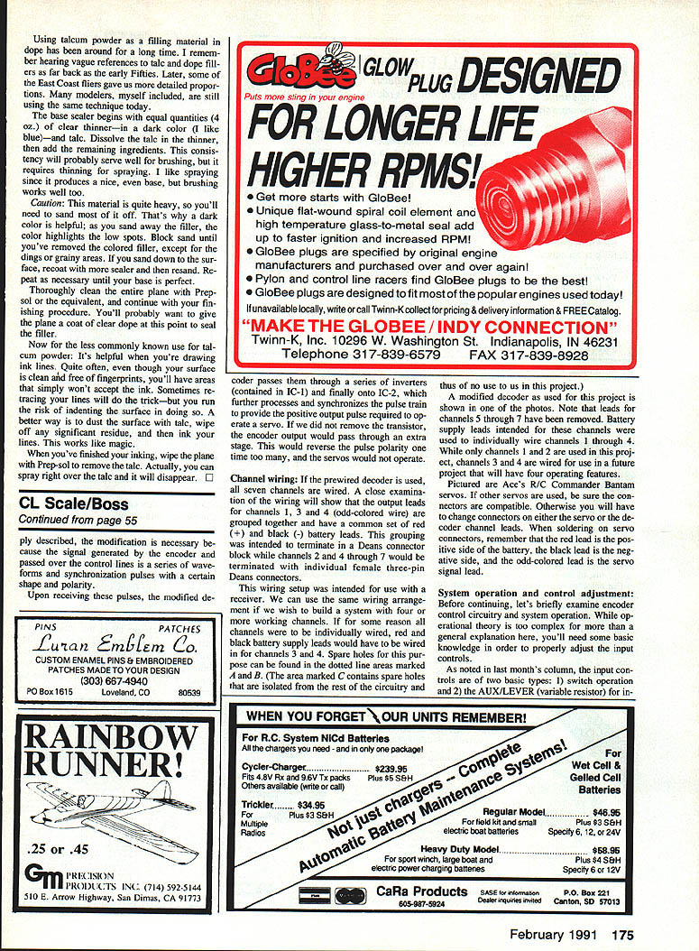
A modified decoder as used for this project is shown in one of the photos. Note that leads for channels 5 through 7 have been removed. Battery supply leads intended for these channels were used to individually wire channels 1 through 4. While only channels 1 and 2 are used in this project, channels 3 and 4 are wired for use in a future project that will have four operating features.
Pictured are Ace's R/C Commander Bantam servos. If other servos are used, be sure the connectors are compatible; otherwise you will have to change connectors on either the servo or the decoder channel leads. When soldering on servo connectors, remember that the red lead is the positive side of the battery, the black lead is the negative side, and the odd-colored lead is the servo signal lead.
System operation and control adjustment
Before continuing, let's briefly examine encoder control circuitry and system operation. While operational theory is too complex for more than a general explanation here, you'll need some basic knowledge in order to properly adjust the input controls.
As noted in last month's column, the input controls are of two basic types:
- Switch operation.
- The AUX/LEVER (variable resistor) for incremental control.
Before we can adjust these controls, we must understand something about how their movement affects a particular channel and encoder input.
Our encoder is capable of seven-channel operation. For purposes of explanation, let's assume that all seven channels will be made operational. To achieve that without creating channel-to-channel interference, the encoder must be able to read and control each channel independently and sequentially.
Imagine a time line on which each of our channels has a predetermined space equivalent to a time of two milliseconds (ms). Further imagine that during a specific portion of the 2-ms time period, the channel is operational and sensitive to input control movement. The operation time period can be defined as the 1.5-ms point, ±0.5 ms, of the overall time per channel.
Our objective is to control or vary, through the use of input devices, the voltage input of a channel during its operational period. The two devices we are using (switch and AUX/LEVER) allow us to control the channels in two modes. The switch unit instantaneously shortens or lengthens our operational time period (from the 1.5-ms point) to the 1-ms or 2-ms point for on/off-type control of the channel. On the other hand, the AUX/LEVER (variable resistor) allows us to control a channel in a continuous or incremental manner between the 1-ms and 2-ms points of its operational time period.
When properly adjusted, the AUX/LEVER unit, as a 5,000-ohm (5k) variable resistor, will allow us to continuously control a channel. To adjust the unit, put the lever in its center position and measure the resistance from the center terminal to the outside terminals with an ohmmeter. You should measure about 2.5k ohms on either side. If one side gives a higher reading than the other, adjust (turn) the U-shaped device on the back of the unit until both sides measure about 2.5k ohms.
If you now move the lever from one side to the other, the resistance reading from the center terminal to one outside terminal should have a range of about 1.5k ohms. When connected to the encoder, this resistance range will keep the variation of input voltage in a range that permits continuous operation of the channel within the 1-ms to 2-ms time period. If the input voltage exceeds the rated range, making a channel operational for longer than 2 ms, possible spillover into another channel's time period could cause loss of synchronization of the encoder. As a result, all servos connected to the system could become noisy, jittery and possibly run free.
The switch unit has two 5k-ohm trim pots that should be adjusted to about 2.5k ohms (approximately center position) and connected as shown in the encoder wiring sketch. The switch unit will provide on/off operation of a channel and keep it within its respective time period.
Once the entire system is set up, if you find that a single servo is noisy, buzzes or jitters, recheck the input device settings. If these are okay, check whether the servo is properly centered. If it isn't, refer to the manufacturer's instructions to adjust the servo's centering.
Next month I'll conclude with a discussion of overall system connections, insulated lines, wiring for the plane's battery supply and a way of insulating line clips.
Here's a listing of the Ace R/C parts used in this portion of the project:
- Digital proportional RX decoder (#121GC), $18.95
- Plastic decoder box (#PLA201), $2.00
- Deans connectors three-pin sets @ $1.75 per set, and/or three-pin Deans connector block (#149622)
- Two Bantam servos (#14926B), $26.45 each
Approximate cost of the decoder assembly with two channels is $85 to $90, not including miscellaneous wire, solder and batteries.
Please send ideas, notices of upcoming CL Scale contests and especially photos of CL Scale activity to me at the address at the very top of this column.
Transcribed from original scans by AI. Minor OCR errors may remain.

