
CONTROL LINE SCALE
Bill Boss 77-06 269th St. New Hyde Park, NY 11040
Overview
In the July column I went back to basics with some words about installing leadout guides. This month I step back again to review the use and makeup of the standard three-line bellcrank system that CL fliers have used for many years. I'll also cover some of the problems associated with making the system and choosing three-line bellcranks.
Although I'll frame this for Scale, the three-line system is also used by many CL modelers for regular sport or fun-flying and Navy Carrier. The three-line control system is composed of a special three-line control handle, three lines of solid or stranded wire, and a special three-line bellcrank that is matched to the handle. It can be troublesome if care is not taken in making the three lines and selecting the right handle and bellcrank.
Three-line system components
- Three-line control handle (special cam action to move lines in opposite directions)
- Three lines (solid or stranded wire sized for aircraft weight)
- Three-line bellcrank matched to the handle
The control handle has a built-in cam action that allows the elevator and engine speed-control lines to move in opposite directions when the control lever, or finger trigger, at the top of the handle is moved through its operating range.
Tables in the Academy of Model Aeronautics' Competition Regulations booklet specify the size of wire to be used for the weight of any particular aircraft for Scale and Navy Carrier. If you're using a three-line system in a model built just for sport or fun-flying, I suggest that you adhere to the line sizes recommended in the table for Scale models. All of the line sizes for model weights in the tables have been set for safety purposes.
Types of three-line systems
Two types of three-line systems have been used throughout the years:
- J. Roberts Sturdi-Built system
- LR (GS) Products Ltd. handle and bellcranks
Each type has the throw of the handle control lever and travel of the bellcrank as a matched set, and problems arise when you try to mix the handles and bellcranks.
The systems provide a means to control an airplane's engine throttle and other operating features such as dropping bombs and retracting landing gear. To obtain a successfully operating setup, you must follow basic instructions when making the system.
Balance and setup
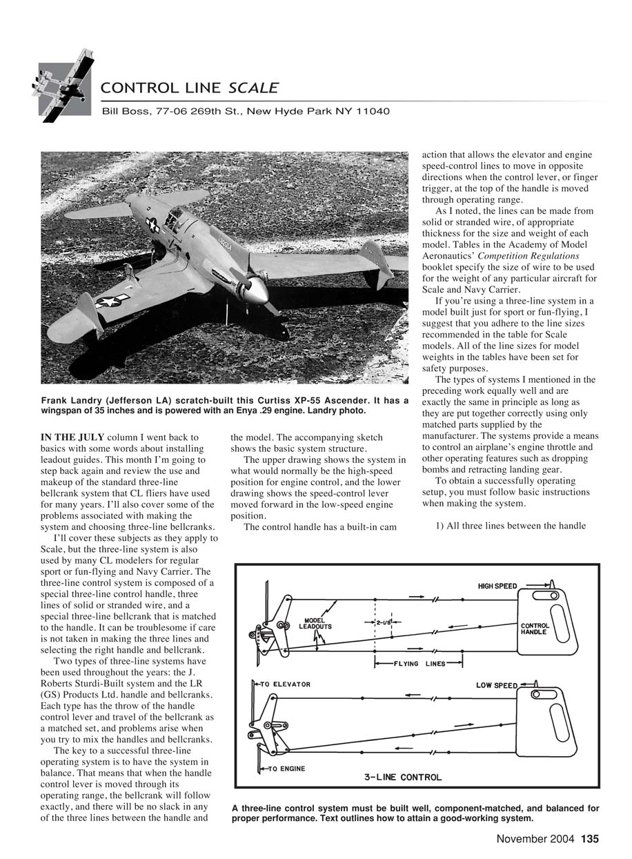
The key to a successful three-line operating system is to have the system in balance. That means that when the handle control lever is moved through its operating range, the bellcrank will follow exactly, and there will be no slack in any of the three lines between the handle and the model. The accompanying sketch shows the basic system structure. The upper drawing shows the system in what would normally be the high-speed position for engine control, and the lower drawing shows the speed-control lever moved forward in the low-speed engine position.
The following are essential when building the system:
- All three lines between the handle and the model's leadouts must be exactly the same length.
- The model's control (third line) leadout must be 2-1/8 inches longer than the elevator-control leadouts. The 2-1/8-inch measurement must be made when the elevator leadouts are pulled tight (which would be the system's high-speed position) and held even with each other. If you build the system as specified, you should have a balanced setup that maintains equal tension on the three lines through the entire range of operation.
This explanation is based on the idea that the control handle and model unit are a matched set from the same manufacturer. I point this out because even though the operation of the two systems mentioned above are the same in principle, there is a basic difference between them.
Mixing components — travel differences and risks
The amount of travel of the third, or control, line of the J. Roberts Sturdi-Built units is approximately 1-1/8 inches, and the LR Products (GS) units have a travel of approximately 1-3/8 inches — a difference of 1/4 inch. If you mix the components, you must consider the difference in travel and the possibility of improper operation.
- If you use the J. Roberts Sturdi-Built handle with the LR Products control unit, you will be unable to obtain the maximum travel available in the LR unit. You would have to plan your operational functions accordingly.
- If you use the LR handle with the J. Roberts Sturdi-Built control unit, the control lead will have more travel than the airplane’s control unit. This combination could result in slack elevator control lines, in which case the full weight and pull of the flying model would be on the control line (third line), causing an unsafe condition.
The solution is to be sure of what you are doing: ensure all lines are of equal length, be aware of the travel of the matched units, and, if in doubt, measure the travel of the control lead at the handle and the travel at the control unit and compare. If you mix components, adjustments must be made.
Current availability — Brodak Manufacturing
Only one system is now widely available: Brodak Manufacturing's. Talking with John Brodak, I learned that the original J. Roberts Sturdi-Built units (distributed in the early 1980s) and the LR Products handle and bellcrank units are incompatible. The LR Products units were much improved in sturdiness and had more travel in the third-line operation.
Brodak offers the heavy-duty Brodak-J. Roberts three-line bellcrank system. The company also offers heavy-duty handles and an assortment of short- and long-span upright and inverted bellcranks. They come in 2½- and 3½-inch spans for elevator-line connections. The short span allows for quicker elevator movement and the longer span provides for slower elevator action suited to slow, rise-off-ground takeoffs and precise flight maneuvers.
Whether you use the inverted or the upright unit will depend on the kind of model you have, such as sport or Precision Scale, and where it is mounted in the fuselage or wing. If you employ the Brodak three-line system, you can be sure that you will be using a matched set of controls that provide full functionality and smooth operation.
For further details about the three-line bellcrank and all the other CL products that Brodak sells, contact:
Brodak Manufacturing 100 Park Ave. Carmichaels, PA 15320 Phone: (724) 966-2726 Web: www.brodak.com
Contributions and contact
Please send ideas, notice of upcoming CL Scale events, contest reports, and especially photos of CL Scale activity to me at the address at the top of this column.
MA
Transcribed from original scans by AI. Minor OCR errors may remain.

