
Control Line Scale - 2006/08
Bill Boss [[email protected]]
Details of Clancy Arnold’s U/Tronics control system
In the June column I wrote about Clancy Arnold’s solution for hiding the elevator pushrod within a profile fuselage to improve a model’s overall appearance. Clancy believes there are two aspects to building a model: technical and artistic. In the last column I provided a technical approach to making an artistic improvement in a profile model. This month I provide information about Clancy’s U/Tronics control system, which he terms an “artistic design” to enhance the technical aspects of building and flying a control-line (CL) aircraft.
Clancy is providing a series of electronic systems that would meet any CL scale modeler’s needs in controlling an airplane’s operational features. The systems can be supplied in single- or multiple-channel versions. Clancy supplies only the electronic module — not the battery, servos, miscellaneous connectors, etc.
U/Tronics units
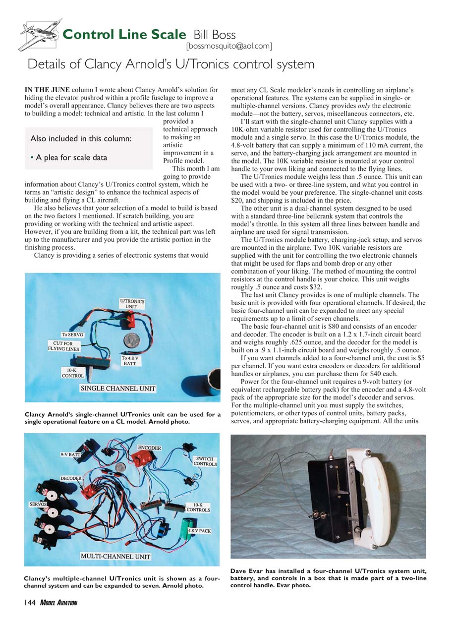
- Single-channel unit
- Supplied with a 10K-ohm variable resistor used for controlling the U/Tronics module and a single servo.
- The U/Tronics module, a 4.8-volt battery capable of supplying a minimum of 110 mA, the servo, and the battery-charging jack are mounted in the model.
- The 10K variable resistor is mounted at the control handle (to your liking) and connected to the flying lines.
- Module weight: less than 0.5 ounce.
- Usable with a two- or three-line system; specific control function is at the modeler’s preference.
- Price: $20 (shipping included).
- Dual-channel unit
- Designed for use with a standard three-line bellcrank system that controls the model’s throttle; all three lines between handle and airplane are used for signal transmission.
- The U/Tronics module, battery, charging jack, and servos are mounted in the airplane.
- Two 10K variable resistors are supplied for controlling the two electronic channels (examples: flaps and bomb drop).
- Mounting of control resistors at the handle is up to the builder.
- Unit weight: roughly 0.5 ounce.
- Price: $32.
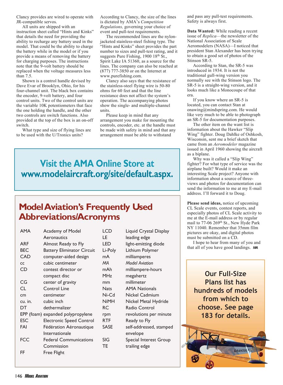
- Multiple-channel unit (basic four-channel, expandable)
- Basic unit provides four operational channels; expandable up to seven channels.
- Basic four-channel unit: $80; consists of an encoder and decoder.
- Encoder: 1.2 x 1.7 inch circuit board, ~0.625 ounce.
- Decoder: 0.9 x 1.1 inch circuit board, ~0.5 ounce.
- Additional channels: $5 per channel.
- Extra encoders or decoders (for additional handles or airplanes): $40 each.
- Power requirements:
- Encoder: 9-volt battery (or equivalent rechargeable pack).
- Decoder and servos: 4.8-volt pack of appropriate size.
- You must supply switches, potentiometers, other control units, battery packs, servos, and appropriate battery-charging equipment.
- All units are wired to operate with JR-compatible servos.
All units are shipped with an instruction sheet called “Hints and Kinks,” which details the need for providing the ability to recharge any battery used in the model. This could be the ability to charge the battery while in the model or to provide a means of removing the battery for charging. The instructions note that the 9-volt battery should be replaced when the voltage measures less than 7.5 volts.
Flying lines and pull-test requirements
- The size and type of flying lines are dictated by the AMA’s Competition Regulations, which govern your choice of event and pull-test requirements.
- Clancy recommends nylon-jacketed stainless-steel fishing lines.
- The “Hints and Kinks” sheet provides part numbers, sizes, and pull-test ratings, and suggests Pure Fishing as a source:
- Pure Fishing, 1900 18th St., Spirit Lake, IA 51360
- Toll-free: (877) 777-3850
- Web: www.purefishing.com
- Clancy notes the resistance of the stainless-steel flying wire is 50–80 ohms for 60 feet and that line resistance does not affect the system’s operation.
Safety and mounting
Please keep in mind that any arrangement you make for mounting the controls, encoder, etc., at the handle must be made with safety in mind and must be able to withstand and pass any pull-test requirements. Safety is always first.
Photos accompanying the original article show the single- and multiple-channel units.
Data Wanted / A plea for scale data
While reading a recent issue of Replica — the newsletter of the National Association of Scale Aeromodellers (NASA) — I noticed that president Stan Alexander has been trying to obtain good photos of the Stinson SR-5.
- Stinson SR-5
- Introduced in 1934.
- Not the traditional gull-wing version with the Stinson logo; the SR-5 is a straight-wing version and resembles a Monocoupe of that era.
- If you know where an SR-5 is located, contact Stan at [email protected]. He would like to photograph an SR-5 for documentation purposes.
- Hawker “Slip Wing” fighter
- Doug Dahlke of Oshkosh, Wisconsin, sent a brief sketch from Aeromodeller magazine (April 1960) showing the aircraft as a biplane.
- Questions: Why was it called a “Slip Wing” fighter? For what service was the airplane built? Would it make an interesting scale project?
- Anyone with information or a source of three-views and photos for documentation can send the information to me at my email address; I’ll forward it to Doug.
Please send ideas, notice of upcoming CL scale events, contest reports, and especially photos of CL scale activity to me at my email address or by regular mail to:
77-06 269th St. New Hyde Park, NY 11040
35mm film pictures are acceptable; digital photos must be submitted on a CD.
I hope to hear from many of you and that all of you have good landings.
MA
Transcribed from original scans by AI. Minor OCR errors may remain.

