
Control Line Scale - 2006/12
Bill Boss [[email protected]]
Frank Beatty models the obscure Pasped Skylark
THE PASPED SKYLARK is a one-of-a-kind aircraft built in 1935 by Fred Pastorius and Stanley Pederson. The first word of the airplane’s name was taken from the first three letters of the owners’ last names.
The Skylark has been seen at aircraft tours and shows for many years. Time, use, and several changes of ownership had taken its toll on the aircraft, and sometime before 2002, owner Robert “Buzz” Penny and restorer Tom Brown returned the airplane to its original factory configuration.
At the 2002 Experimental Aircraft Association AirVenture show in Oshkosh, Wisconsin, the Skylark was awarded the Antique Bronze Age Champion trophy. That’s remarkable for a 67-year-old aircraft, and it’s a tribute to a remarkable restoration.
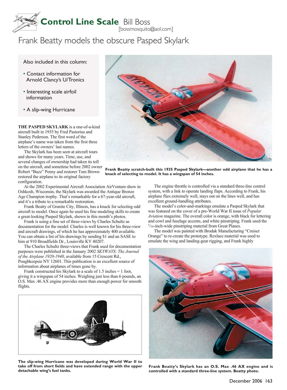
Frank Beatty of Granite City, Illinois, has a knack for selecting odd aircraft to model. Once again he used his fine modeling skills to create a great-looking Pasped Skylark, shown in this month’s photos.
Frank is using a fine set of three-views by Charles Schultz as documentation for the model. Charles is well known for his three-view and aircraft drawings, of which he has approximately 400 available. You can obtain a list of his drawings by sending $1 and an SASE to him at 910 Broadfields Dr., Louisville KY 40207.
The Charles Schultz three-views that Frank used for documentation purposes were published in the January 2002 SKYWAYS: The Journal of the Airplane 1920-1940, available from 15 Crescent Rd., Poughkeepsie NY 12601. This publication is an excellent source of information about airplanes of times gone by.
Frank constructed his Skylark to a scale of 1.5 inches = 1 foot, giving it a wingspan of 54 inches. Weighing just less than 6 pounds, an O.S. Max .46 AX engine provides more than enough power for smooth flights.
The engine throttle is controlled via a standard three-line control system, with a link to operate landing flaps. According to Frank, his airplane flies extremely well, stays out on the lines well, and has excellent ground-handling attributes.
The model’s color and markings emulate a Pasped Skylark that was featured on the cover of a pre-World War II issue of Popular Aviation magazine. The overall color is orange, with black for lettering and cowl and fuselage accents, and white pinstriping. Frank used the 1/16-inch-wide pinstriping material from Great Planes.
The model was painted with Brodak Manufacturing "Cruiser Orange" to re-create the prototype. Rexlace material was used to emulate the wing and landing-gear rigging, and Frank highly recommends it. The material comes in spools and in various colors, and you can find it in most craft stores.
Thanks to Frank Beatty for providing us with a look at another of his outstanding models.
An Omission
In the last column I was so engrossed in writing about Clancy Arnold's U/Tronics control systems that I left out an important item: how to contact him about obtaining further information or ordering one of his great systems.
You can reach Clancy Arnold at:
- Address: 4006 Eagle Cove Ct., Indianapolis IN 46254
- Tel.: (317) 387-1940
- E-mail: [email protected]
I hope many of you avail yourself of his services.
Airfoil Theory
When Clancy contacted me about the omission of contact information for his U/Tronics systems, he told me about the book Theory of Wing Sections by Ira H. Abbott and Alfred E. Von Doenhoff of NASA, published by Dover Publications.
The feature that would be most interesting to modelers is in the last half of the book. The section contains airfoil ordinates for almost every known airfoil. With this information it is easy to generate true scale airfoils for any size of model. The information is given as a percentage of wing chord for each plot point on the airfoil (wing) surface.
The paperback edition of the book sells for $12.95, and it is most likely available at most large bookstores.
Clancy noted that he encountered an interesting problem with wing location when building his F/A-18A: a US Navy version of the Hornet built by McDonnell Douglas. The airfoil the company used, per the aforementioned book, called for a sharp leading edge. However, the company modified the airfoil by rounding the leading edge, thereby reducing the actual wing chord by 4–5 inches on the full-scale airplane. Clancy noted that at a scale of 8.33:1, this change reduced the chord of the model's wing by roughly half.
Take caution if you are designing your own scale model. Make sure airfoils are done correctly for all flying surfaces and that their locations are correct.
Slip-Wing Fighter
In the August column I asked for information about the Hawker Hurricane slip-wing fighter. The response was not overwhelming, but the replies I received were excellent.
Joseph Valenta sent me copies of pages from Aircraft Profile Publication No. 111 and Squadron Signals Publication No. 72, both of which contained photos of the Hawker Hurricane Mk I slip-wing version in flight and on the ground.
The photo captions for the slip wing in flight (and on the ground) noted that the airplane was one of an original batch of Hurricanes, L1884. It was shipped to Canada in 1938 to become Royal Canadian Air Force #321.
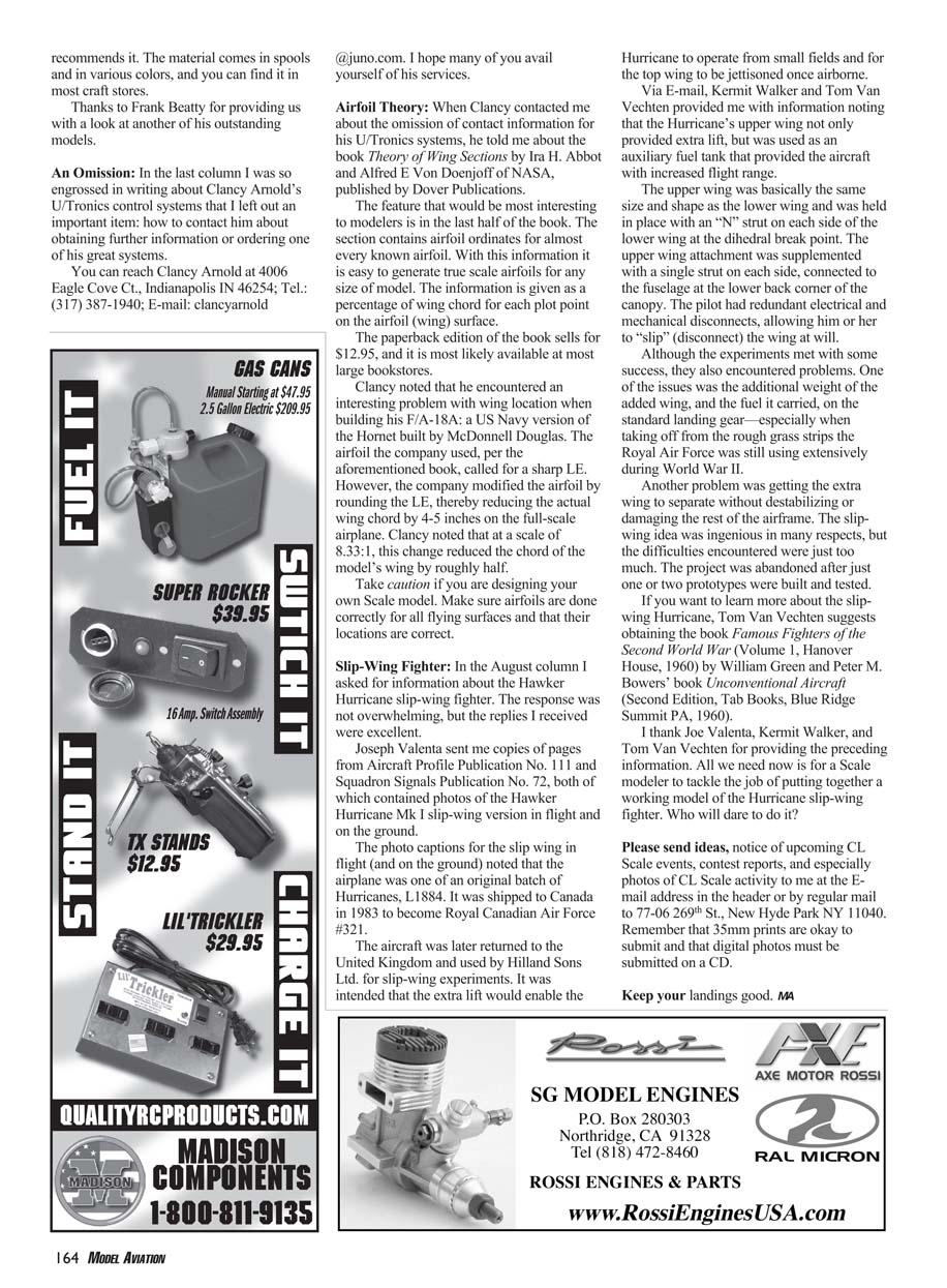
The aircraft was later returned to the United Kingdom and used by Hilland Sons Ltd. for slip-wing experiments. It was intended that the extra lift would enable the Hurricane to operate from small fields and for the top wing to be jettisoned once airborne.
Via e-mail, Kermit Walker and Tom Van Vechten provided me with information noting that the Hurricane's upper wing not only provided extra lift, but was used as an auxiliary fuel tank that provided the aircraft with increased flight range.
The upper wing was basically the same size and shape as the lower wing and was held in place with an "N" strut on each side of the lower wing at the dihedral break point. The upper wing attachment was supplemented with a single strut on each side, connected to the fuselage at the lower back corner of the canopy. The pilot had redundant electrical and mechanical disconnects, allowing him or her to "slip" (disconnect) the wing at will.
Although the experiments met with some success, they also encountered problems. One of the issues was the additional weight of the added wing, and the fuel it carried, on the standard landing gear—especially when taking off from the rough grass strips the Royal Air Force was still using extensively during World War II.
Another problem was getting the extra wing to separate without destabilizing or damaging the rest of the airframe. The slip-wing idea was ingenious in many respects, but the difficulties encountered were just too much. The project was abandoned after just one or two prototypes were built and tested.
If you want to learn more about the slip-wing Hurricane, Tom Van Vechten suggests obtaining:
- Famous Fighters of the Second World War (Volume 1, Hanover House, 1960) by William Green
- Unconventional Aircraft (Second Edition, Tab Books, Blue Ridge Summit PA, 1960) by Peter M. Bowers
I thank Joe Valenta, Kermit Walker, and Tom Van Vechten for providing the preceding information. All we need now is for a scale modeler to tackle the job of putting together a working model of the Hurricane slip-wing fighter. Who will dare do it?
Please send ideas, notice of upcoming C/L Scale events, contest reports, and especially photos of C/L Scale activity to me at the e-mail address in the header or by regular mail to:
- 77-06 269th St., New Hyde Park NY 11040
Remember that 35mm prints are okay to submit and that digital photos must be submitted on a CD.
Keep your landings good. MA
Transcribed from original scans by AI. Minor OCR errors may remain.

