
Control Line Scale — Bill Boss [[email protected]]
The West Michigan Smoke Rings hosts its first CL Scale meet
Leroy Heikes (Plainwell, MI) submitted a report about the First Annual CL Scale Competition of the West Michigan Smoke Rings club. According to Leroy, the club was in existence only roughly a year and a half at the time of the contest—June 24, 2006—which was an effort by the club members to promote CL Scale in their area.
The contest included the following divisions:
- F4B
- Sport
- Profile (with a Junior category)
- Fun Scale
The competition was held in the Plainwell High School parking lot, where the fliers enjoyed a fine macadam-paved area on which to fly. There is nothing like a smooth surface from which to perform great takeoffs and landings, making scale-model flying more enjoyable.
The club had a total of 18 competitors, with five entries in Sport and five in Junior Profile. The Bauer family attended in force: Charlie, Jason, Aaron, Peter, and Kathy Bauer—several of whom placed well in Sport, Profile, and Junior Profile.
Winners included:
- Charlie Bauer — 1st in Sport (flying a Gee Bee racer)
- Mindy Alberty — 1st in Junior Profile
- Kathy Bauer — 1st in Profile
- Chuck Snyder — 1st in F4B (Hs 129)
- R. Garret — 1st in Fun Scale (triplane)
- Justin McCauley — 1st in Junior Fun Scale (Brodak trainer)
Leroy was the Contest Director and thanked the Plainwell High School authorities for allowing the club to hold the contest at the site and use the restroom and concession facilities. The club will hold the second annual meet at the school on June 30, 2007. This competition will again afford scale modelers in Michigan and surrounding areas an opportunity to compete. Consider coming out to support as a participant or spectator and enjoy a great day of CL scale-model flying.
Simulating Corrugations on Flying Surfaces
I received an E-mail from Tom Telesca announcing that he had just completed an L-19 Bird Dog. He had a hard time creating corrugations on the flying surfaces and wondered if there might be a better way. His method was to use string and hardwood or balsa strips.
Tom noticed the picture of Karl Georg Krafft’s Boeing 100 in an October column. The text read that the corrugations on that model’s flying surfaces were simulated using corrugated cardboard. An E-mail to Karl Georg brought the following information.
The corrugated cardboard is the type used for decorations and wrapping presents, comes in many colors, and can be found in craft-type stores or shops that sell paper goods. The cardboard is roughly 2 mm thick and the corrugations are approximately 4 mm apart measured from top to top. To meet the scale of the corrugations for the Boeing 100, Karl Georg had to cut away every other corrugation. He then glued the cardboard onto balsa parts and did some filling, sanding, and painting.
The lengths to which modelers go and the ingenious things they come up with during the building process never cease to amaze me. The craft stores mentioned can also be a great source for many other modeling items. I like to wander up and down the aisles that contain all sorts of pins and fasteners. In addition to finding “T”-type pins that most of us use during model construction, there are pins with round heads that come in many sizes and colors—good for simulating control handles in the cockpit. You will also find many types of transferable lettering that can be used to apply finishing touches.
The next time you get the opportunity to go to a craft store, don't pass it up. Walk the aisles and let your imagination and a little ingenuity help you discover useful items.
Hiding the Elevator Pushrod Revisited
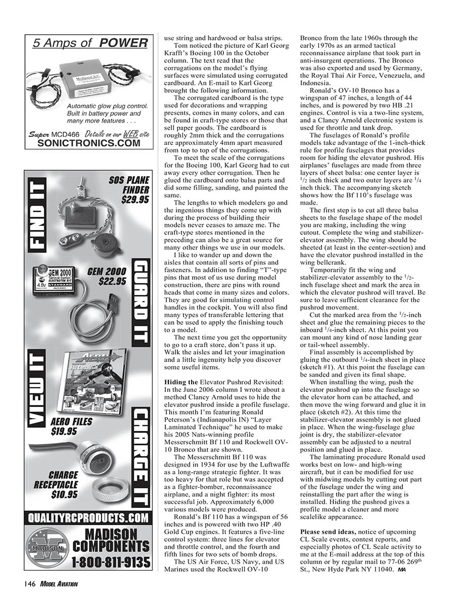
In the June 2006 column I wrote about a method Clancy Arnold uses to hide the elevator pushrod inside a profile fuselage. This month I'm featuring Ronald Peterson's (Indianapolis, IN) "Layer Laminated Technique" that he used to make his 2005 Nats-winning profile Messerschmitt Bf 110 and Rockwell OV-10 Bronco.
The Messerschmitt Bf 110 was designed in 1934 for use by the Luftwaffe as a long-range strategic fighter. It was too heavy for that role but was accepted as a fighter-bomber, reconnaissance airplane, and night fighter—its most successful job. Approximately 6,000 various models were produced.
Ronald's Bf 110 has a wingspan of 56 inches and is powered by two GP .40 Gold Cup engines. It features a five-line control system: three lines for elevator and throttle control, and the fourth and fifth lines for two sets of bomb drops.
The Rockwell OV-10 Bronco was used by the US Air Force, US Navy, and US Marines from the late 1960s through the early 1970s as an armed tactical reconnaissance airplane that took part in anti-insurgent operations. The Bronco was also exported and used by Germany, the Royal Thai Air Force, Venezuela, and Indonesia.
Ronald's OV-10 Bronco has a wingspan of 47 inches, a length of 44 inches, and is powered by two HB .21 engines. Control is via a two-line system, and a Clancy Arnold electronic system is used for throttle and tank drop.
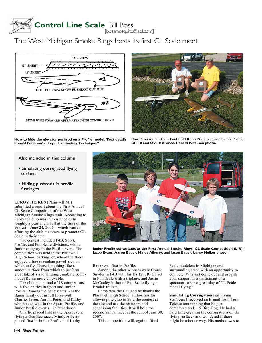
Ronald's profile fuselages take advantage of the 1-inch-thick rule for profile fuselages that provides room for hiding the elevator pushrod. His fuselages are made from three layers of sheet balsa: one center layer 1/2 inch thick and two outer layers 1/4 inch thick. The accompanying sketch (not shown) illustrates how the Bf 110's fuselage was made.
Steps Ronald uses for the layer laminated technique:
- Cut all three balsa sheets to the fuselage shape of the model, including the wing cutout.
- Complete the wing and stabilizer-elevator assembly. The wing should be sheeted (at least in the center section) and have the elevator pushrod installed in the wing bellcrank.
- Temporarily fit the wing and stabilizer-elevator assembly to the 1/2-inch fuselage sheet and mark the area in which the elevator pushrod will travel. Be sure to leave sufficient clearance for pushrod movement.
- Cut the marked area from the 1/2-inch sheet and glue the remaining pieces to the inboard 1/4-inch sheet. At this point you can mount any nose landing gear or tail-wheel assembly.
- Final assembly is accomplished by gluing the outboard 1/4-inch sheet in place. At this point the fuselage can be sanded and given its final shape (see sketch #1).
- When installing the wing, push the elevator pushrod up into the fuselage so the elevator horn can be attached, then move the wing forward and glue it in place (see sketch #2). At this time the stabilizer-elevator assembly is not glued in place.
- When the wing-fuselage glue joint is dry, adjust the stabilizer-elevator assembly to a neutral position and glue it in place.
The laminating procedure works best on low- and high-wing aircraft, but it can be modified for mid-wing models by cutting out part of the fuselage under the wing and reinstalling that part after the wing is installed. Hiding the pushrod gives a profile model a cleaner and more scale-like appearance.
Please send ideas, notice of upcoming CL Scale events, contest reports, and especially photos of CL Scale activity to me at the E-mail address at the top of this column or by regular mail to: 77-06 269th St., New Hyde Park, NY 11040.
MA
Transcribed from original scans by AI. Minor OCR errors may remain.

