
The Eiben/Hubin multichannel electronic control system
Bill Boss [[email protected]]
Background
In the February 2009 column I featured a multichannel electronic control system by Al Cargil of Warwick, Pennsylvania that could be used with either electric- or glow-powered models. The push by many for the use of electronics for throttle and other flight or operational features seemed to imply that we no longer needed the standard three-line control system that has been the mainstay for scale, Navy carrier, and sport flying for many years.
Joe Eiben of Essex, Maryland, has provided a new idea: a small electronic unit that puts some real life back into the use of the standard three-line system. Joe’s system consists of a tiny electronic unit, a battery supply, a microswitch, and one or two servos, allowing you to retain three-line throttle control while independently operating flaps, landing gear, or other features depending on the prototype being modeled.
Also included in this column:
- Terrafugia Transition
System versions
This unit comes in three versions:
- Flaps/Gear Manager, Model FGM-1 — controller board that cycles flaps and landing gear retraction together.
- Gear Manager, Model GM-1 — single-operation controller board for landing gear retraction.
- Flaps Manager, Model FM-1 — single-operation controller board for flaps (uses a standard servo rather than a 180° retract servo).
Joe worked with Will Hubin of Kent, Ohio; Will designed the controller boards.
Components and hookup
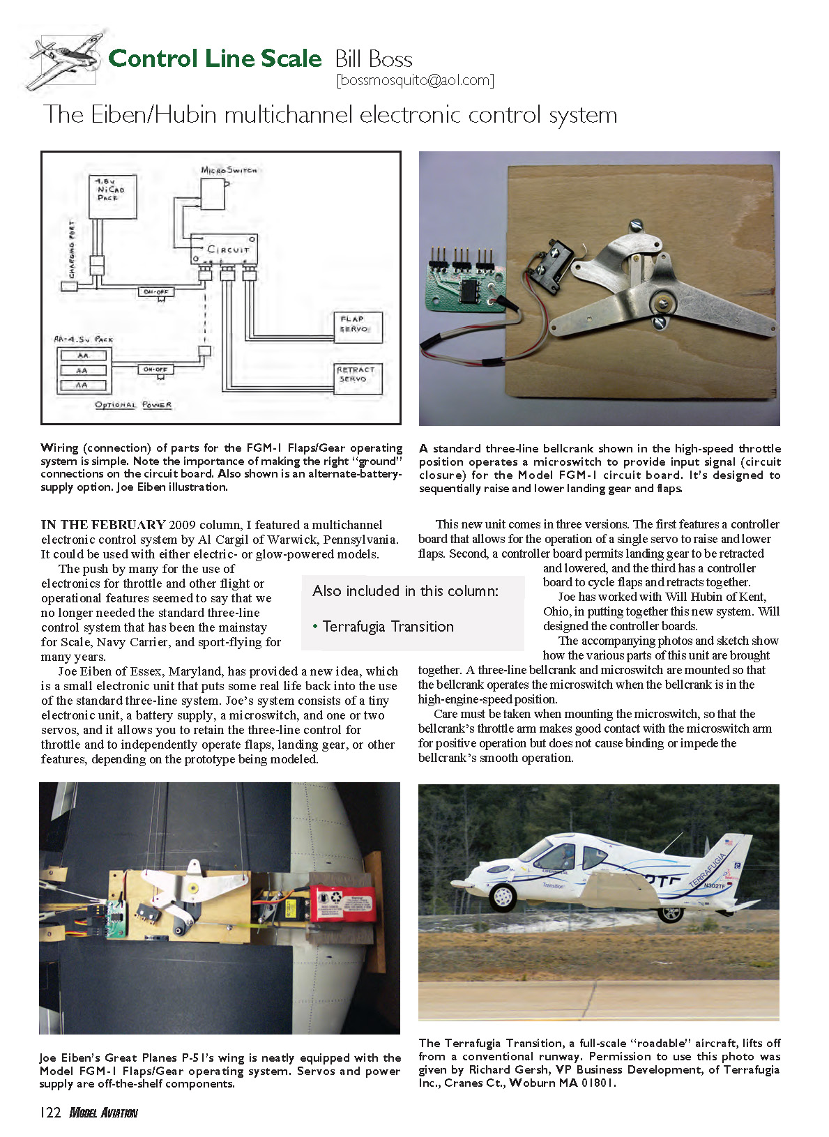
The system components include:
- 4.8-volt Ni-Cd flight pack (standard) or an alternate supply using three standard "AA" flashlight-type cells.
- Flaps/Gear Manager circuit board (FGM-1) or the single-operation boards (GM-1 or FM-1).
- A gear-retraction servo (for retracts) and/or a standard servo for flap operation.
- A microswitch mounted so it is actuated by the three-line bellcrank in a selected throttle position.
- An on/off switch and a charging port to charge the flight pack while installed in the model.
The three-line bellcrank and microswitch are mounted so that the bellcrank operates the microswitch when the bellcrank is in the high-engine-speed position (or optionally in the low position — see Installation notes). Care must be taken when mounting the microswitch so the bellcrank’s throttle arm makes good contact with the microswitch arm for positive operation without binding or impeding smooth bellcrank movement.
The sketch in the original article shows the three-pin connections for servos and battery supply. When connecting the three-pin connectors of the servos and battery pack to the circuit board, pay close attention: the ground lead of the servos and battery supply must be connected to the ground terminals on the circuit board to prevent damage. Grounds on the circuit board terminals and servo connectors are marked with a “G.” The black (or brown) lead on servos and the battery pack is generally the ground lead.
Operation details
FGM-1 (Flaps/Gear Manager)
- When powered up, both flaps and landing gear are lowered.
- After a 10-second delay, the program checks the microswitch. If closed, the system raises the flaps smoothly over a 4-second period and then raises the landing gear.
- After a 9-second delay, the system is ready to accept a command from the microswitch to lower the flaps smoothly over 4 seconds and then lower the landing gear.
- Each subsequent closure of the microswitch repeats the cycle.
GM-1 (Gear Manager — single operation)
- Designed to raise and lower landing gear using a retract servo when triggered by the microswitch.
- On power-up, the system lowers the landing gear.
- After a 5-second delay (to prevent consecutive movements), the program checks the microswitch and raises the landing gear when a closure is detected.
- After another 5-second delay the system is ready to accept a command to lower the landing gear.
- Each closure of the microswitch thereafter repeats the cycle.
FM-1 (Flaps Manager — single operation)
- Designed to operate flaps using a standard servo instead of the 180° retract servo.
Installation notes and options
- The description above assumes the microswitch is triggered by the high-throttle position of the bellcrank; however, the microswitch can be installed to trip with the bellcrank in the low-engine-speed position if preferred. Joe used the high-speed throttle position for triggering the microswitch to provide better control of low-speed operation for landing, taxiing, and possible engine cutoff.
- If a modeler wants operation independent of throttle position, the microswitch leads can be connected to the leadouts/flying lines with one lead insulated, and a momentary button switch at the control handle can activate the cycle.
Direct questions about system installation/operation should be directed to Joe Eiben (see Sources).
Examples and parts used
- A photo in the original article shows Model FGM-1 neatly installed in the wing of Joe’s 60-size P-51 Mustang (a Great Planes ARF) for operation of flaps and landing gear retraction.
- Joe used servos from Tower Hobbies and Hobbico mechanical retracts for .40- to .60-size models (also available through Tower Hobbies).
Pricing
- FGM-1 (flaps and retraction board): $20 (Will Hubin is selling the circuit board).
- GM-1 or FM-1 (single-operation boards): $15.
- Servos (Tower Hobbies): range about $15 to $30 depending on standard or retract version.
- Microswitches: available from many electronic suppliers (e.g., RadioShack) for about $6–$7.
- Hobbico mechanical retracts: available through Tower Hobbies (sizes noted above).
Conclusion
Joe wanted a simple, foolproof system similar to ones described for many years, made possible by the advent of electric models and electronics. Scale fliers who use three-line control can now add retracting gear and raise/lower flaps on demand, enjoying more realistic flight operations and easier repeated touch-and-gos.
Terrafugia Transition
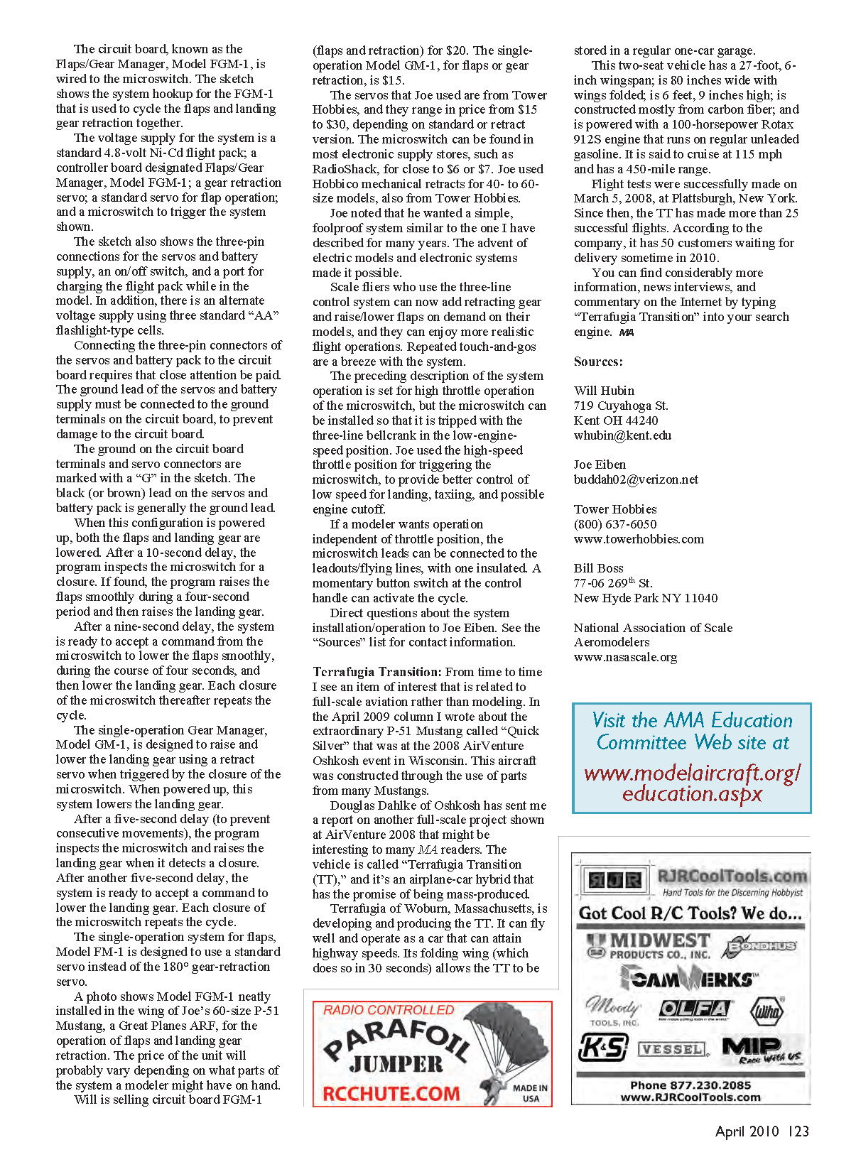
From time to time I include items of interest related to full-scale aviation. Douglas Dahlke of Oshkosh sent a report on a full-scale project shown at AirVenture 2008 that may interest MA readers: the Terrafugia Transition (TT), an airplane–car hybrid developed by Terrafugia of Woburn, Massachusetts.
The TT can fly and operate as a car at highway speeds. Its folding wing (which stows in about 30 seconds) allows the vehicle to be stored in a regular one-car garage. Key specifications:
- Two seats.
- Wingspan: 27 ft 6 in.
- Width with wings folded: 80 in.
- Height: 6 ft 9 in.
- Constructed mostly from carbon fiber.
- Powered by a 100-horsepower Rotax 912S engine that runs on regular unleaded gasoline.
- Cruise speed: approximately 115 mph.
- Range: about 450 miles.
Flight tests were successfully made on March 5, 2008, at Plattsburgh, New York. Since then the TT has completed more than 25 successful flights. According to the company, it had 50 customers waiting for delivery sometime in 2010.
For more information, news interviews, and commentary, search the Internet for “Terrafugia Transition.”
Sources:
- Will Hubin
719 Cuyahoga St. Kent, OH 44240 [email protected]
- Joe Eiben
- Tower Hobbies
(800) 637-6050 www.towerhobbies.com
- Bill Boss
77-06 269th St. New Hyde Park, NY 11040 [email protected]
- National Association of Scale Aeromodelers
Transcribed from original scans by AI. Minor OCR errors may remain.

