
Control Line Scale
Bill Boss [[email protected]]
Line-tension problems
In the April 2010 column I wrote about a multichannel electronic system that Joe Eiben and Will Hubin developed. It was actuated through the use of a microswitch and the throw of the throttle arm of a standard three-line bellcrank.
The column noted that if an aeromodeler wanted to operate the system independently of the bellcrank throttle position, the leads that would have been connected to the microswitch could be connected directly to two insulated lines from the control handle and the system could be triggered by a momentary button switch at the handle. It also suggested that one insulated line could be used.
John Rist sent an e-mail saying he had used one insulated line with his electronic system design and lost an aircraft because of it. He explained that when you go to low throttle, the line tension decreases. The larger insulated line has more drag and tends to pull the model in a direction (up or down) depending on where the line is placed.
John had used the single insulated line for the up line, and, as chance would have it, he was flying on a windy day. When he cut power to the Eindecker he was flying, it came into the wind; enough drag was created on the up line to drive the model up and over the top. That resulted in a crash and its destruction.
If you use any electronic system, do not use a single insulated line on the up or down flying line. If a single insulated line is to be used with the three-line bellcrank, avoid trouble and use the throttle line. Any additional drag on the throttle line would probably not interfere with the overall control of the model, as might happen with the up and down lines. John’s experience also indicates that using one insulated line with a two-line system might be a bad idea.
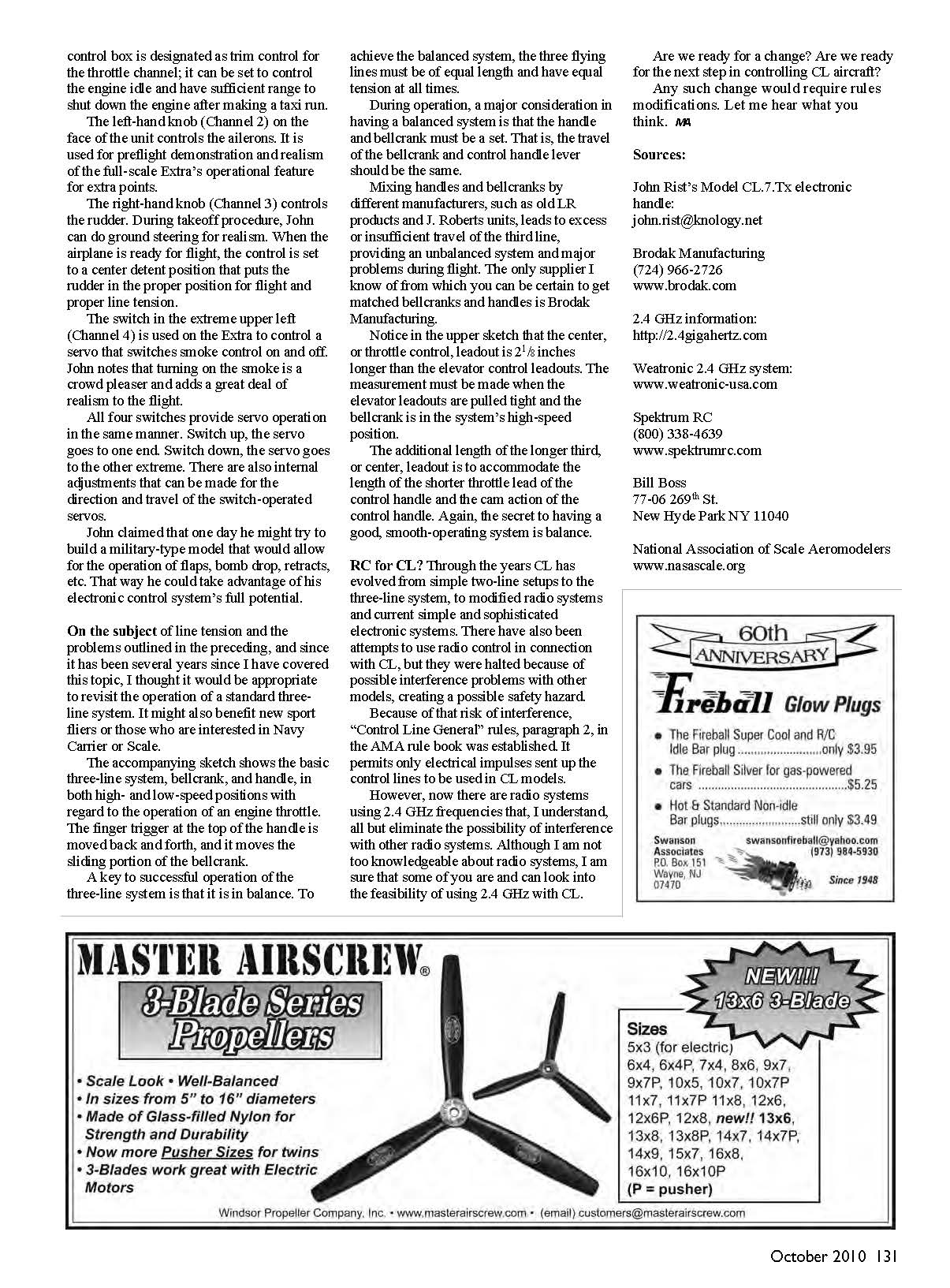
John submitted two photos. One shows him and fellow modeler Ty Marcucci discussing the problem of the one insulated line that caused excess drag and the demise of John’s Eindecker. The other picture is of John’s unique electronic handle that he designated “Model CL.7.Tx.” He is an electronics engineer and devised the handle for his use. It is currently being used to control an Extra 300S powered with a SuperTigre .90 engine.
The handle has seven operational channels, four of which are used for control of the Extra 300S. The bottom slide is Channel 1 and is used for throttle control. The black knob on the left-hand side of the control box is designated as trim control for the throttle channel; it can be set to control the engine idle and has sufficient range to shut down the engine after making a taxi run.
The left-hand knob (Channel 2) on the face of the unit controls the ailerons. It is used for preflight demonstration and realism of the full-scale Extra’s operational feature for extra points. The right-hand knob (Channel 3) controls the rudder. During takeoff, John can do ground steering for realism. When the airplane is ready for flight, the control is set to a center-detent position that puts the rudder in the proper position for flight and proper line tension.
The switch in the extreme upper left (Channel 4) is used on the Extra to control a servo that switches smoke on and off. John notes that turning on the smoke is a crowd pleaser and adds a great deal of realism to the flight.
All four switch-operated channels provide servo operation in the same manner: switch up, the servo goes to one end; switch down, the servo goes to the other extreme. There are also internal adjustments that can be made for the direction and travel of the switch-operated servos.
John said that one day he might try to build a military-type model that would allow for operation of flaps, bomb drop, retracts, etc., to take advantage of his electronic control system’s full potential.
On the subject of line tension and the problems outlined above, and since it has been several years since I covered this topic, I thought it appropriate to revisit the operation of a standard three-line system. It might also benefit new sport fliers or those interested in Navy Carrier or Scale.
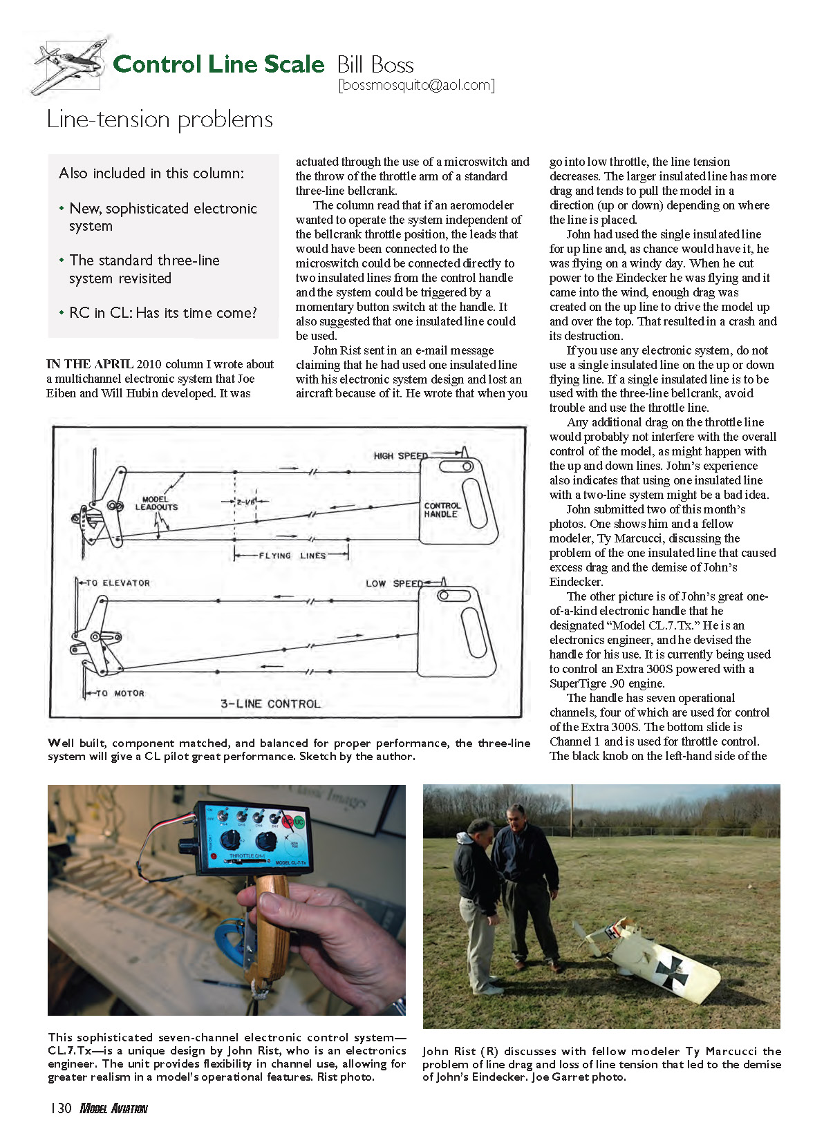
The accompanying sketch shows the basic three-line system, bellcrank, and handle in both high- and low-speed positions with regard to engine throttle operation. The finger trigger at the top of the handle is moved back and forth and moves the sliding portion of the bellcrank.
A key to successful operation of the three-line system is balance. To achieve a balanced system, the three flying lines must be of equal length and have equal tension at all times.
During operation, a major consideration in having a balanced system is that the handle and bellcrank must be a matched set. That is, the travel of the bellcrank and control-handle lever should be the same.
Mixing handles and bellcranks by different manufacturers, such as older LR Products and J. Roberts units, can lead to excess or insufficient travel of the third line, providing an unbalanced system and major problems during flight. The only supplier I know of from which you can be certain to get matched bellcranks and handles is Brodak Manufacturing.
Notice in the upper sketch that the center, or throttle-control, leadout is 2 1/8 inches longer than the elevator-control leadouts. The measurement must be made when the elevator leadouts are pulled tight and the bellcrank is in the system’s high-speed position.
The additional length of the longer third, or center, leadout is to accommodate the length of the shorter throttle lead of the control handle and the cam action of the control handle. Again, the secret to having a good, smooth-operating system is balance.
RC for CL?
Through the years, CL has evolved from simple two-line setups to the three-line system, to modified radio systems and current simple and sophisticated electronic systems. There have also been attempts to use radio control in connection with CL, but they were halted because of possible interference problems with other models, creating a possible safety hazard.
Because of that risk of interference, the “Control Line General” rules (paragraph 2) in the AMA rule book were established. They permit only electrical impulses sent up the control lines to be used in CL models.
However, there are now radio systems using 2.4 GHz frequencies that, I understand, all but eliminate the possibility of interference with other radio systems. Although I am not an expert on radio systems, I am sure some of you are and can look into the feasibility of using 2.4 GHz with CL.
Are we ready for a change? Are we ready for the next step in controlling CL aircraft? Any such change would require rules modifications. Let me hear what you think. — MB
Sources
- John Rist’s Model CL.7.Tx electronic handle: [email protected]
- Brodak Manufacturing: (724) 966-2726, www.brodak.com
- 2.4 GHz information: http://2.4gigahertz.com
- Weatronic 2.4 GHz system: www.weatronic-usa.com
- Spektrum RC: (800) 338-4639, www.spektrumrc.com
Bill Boss 77-06 269th St. New Hyde Park, NY 11040
National Association of Scale Aeromodelers: www.nasascale.org
Transcribed from original scans by AI. Minor OCR errors may remain.

