
Leadout installations
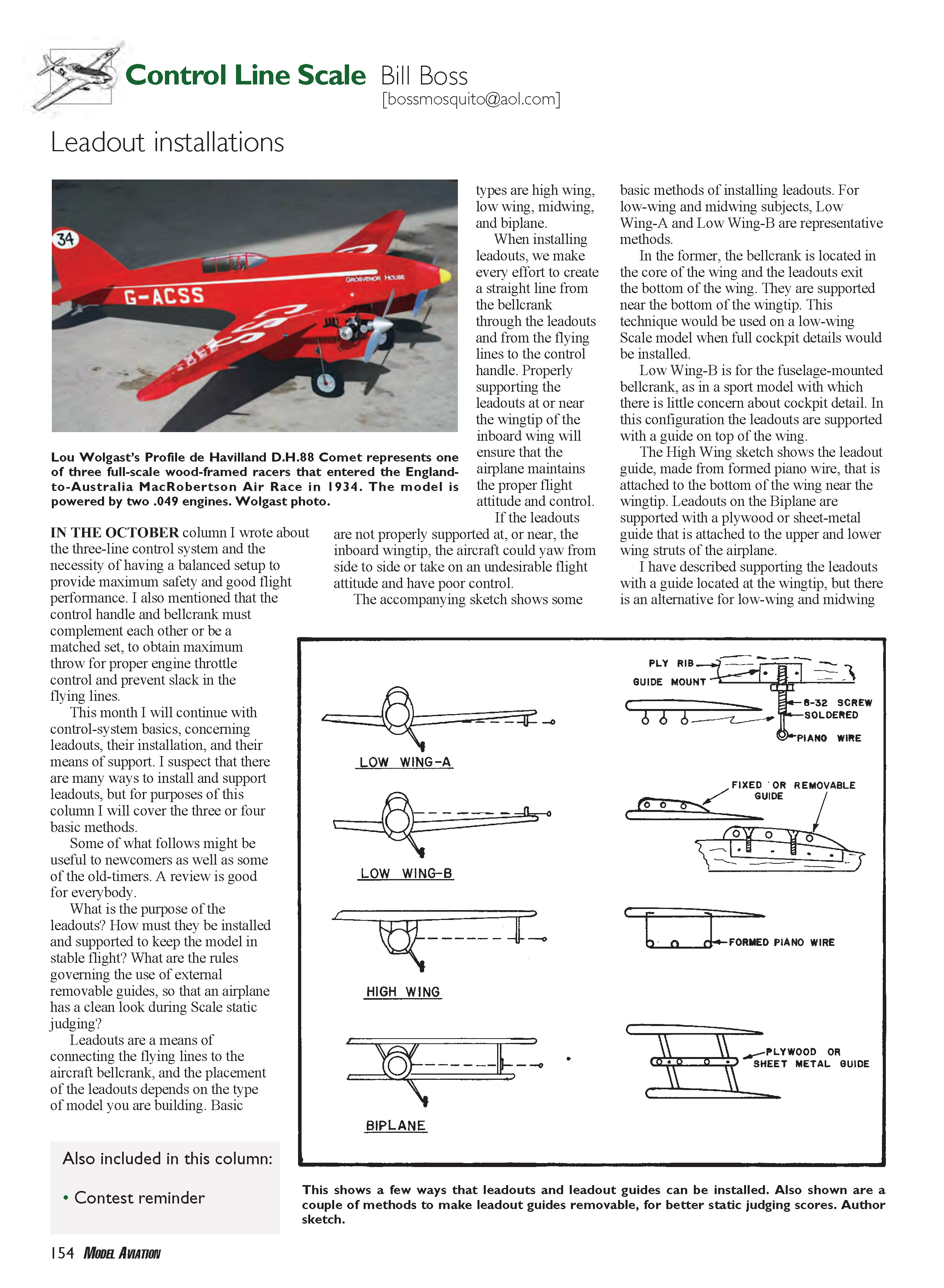
In the October column I wrote about the three-line control system and the necessity of having a balanced setup to provide maximum safety and good flight performance. I also mentioned that the control handle and bellcrank must complement each other or be a matched set to obtain maximum throw for proper engine throttle control and prevent slack in the flying lines.
This month I continue with control-system basics concerning leadouts, their installation, and their means of support. There are many ways to install and support leadouts; for this column I cover three or four basic methods. Some of what follows may be useful to newcomers as well as old-timers. A review is good for everybody.
Purpose of leadouts
Leadouts are the means of connecting the flying lines to the aircraft bellcrank. Their placement depends on the type of model being built. Correct installation and support of the leadouts are essential to keep the model in stable flight and maintain proper control.
Types of models and leadout placement
- High wing
- Low wing
- Midwing
- Biplane
The leadout placement and support method vary with these basic configurations.
Proper installation and support
When installing leadouts, make every effort to create a straight line from the bellcrank through the leadouts and from the flying lines to the control handle. Properly supporting the leadouts at or near the inboard wingtip will help ensure the airplane maintains the correct flight attitude and control.
If leadouts are not properly supported at or near the inboard wingtip, the aircraft can yaw side to side, develop an undesirable flight attitude, and exhibit poor control.
Basic installation methods
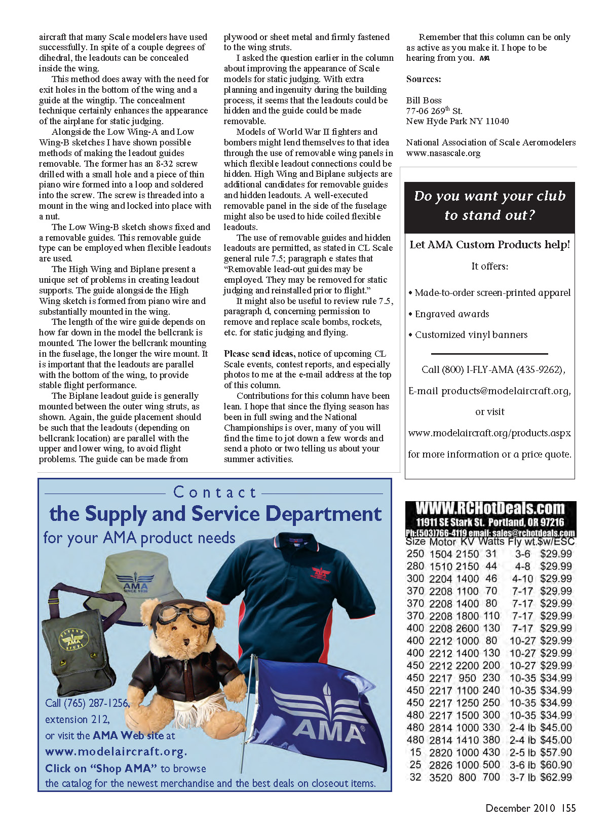
The accompanying sketch (not included here) shows representative methods. Descriptions of the common methods follow.
#### Low Wing-A
- Bellcrank located in the wing core; leadouts exit the bottom of the wing.
- Leadouts are supported near the bottom of the wingtip.
- This technique is typical for a low-wing scale model with full cockpit detailing.
#### Low Wing-B
- Fuselage-mounted bellcrank, common in sport models where cockpit detail is minimal.
- Leadouts are supported with a guide on top of the wing.
For low- and midwing subjects, Low Wing-A and Low Wing-B are representative methods. Alongside those sketches are shown possible removable guide methods.
- One removable-guide method uses an 8-32 screw drilled with a small hole; a piece of thin piano wire is formed into a loop and soldered into the screw. The screw threads into a mount in the wing and is locked with a nut.
- Low Wing-B can show either fixed or removable guides. The removable-guide type is useful when flexible leadouts are used.
#### High Wing
- The leadout guide is formed from piano wire and attached to the bottom of the wing near the wingtip.
- The length of the wire guide depends on how far down in the fuselage the bellcrank is mounted: the lower the bellcrank, the longer the wire mount needs to be.
- It is important that the leadouts are parallel with the bottom of the wing to provide stable flight performance.
#### Biplane
- Leadout guides are generally mounted between the outer wing struts and can be made from plywood or sheet metal.
- Guide placement should ensure the leadouts are parallel with the upper and lower wings (depending on bellcrank location) to avoid flight problems.
- Fasten guides firmly to the wing struts.
Concealed leadouts and removable guides
There is an alternative for low-wing and midwing aircraft: many scale modelers successfully conceal leadouts inside the wing, despite a couple degrees of dihedral. Concealment removes the need for exit holes in the wing bottom and a wingtip guide, improving the airplane's appearance for static judging.
With extra planning and ingenuity during construction, leadouts can be hidden and guides made removable. Examples:
- Models of World War II fighters and bombers may use removable wing panels to hide flexible leadout connections.
- High-wing and biplane subjects are additional candidates for removable guides and hidden leadouts.
- A well-executed removable panel in the fuselage side might hide coiled flexible leadouts.
Rules and judging
Removable guides and hidden leadouts are permitted. CL Scale general rule 7.5, paragraph e, states: "Removable lead-out guides may be employed. They may be removed for static judging and reinstalled prior to flight."
It may also be useful to review rule 7.5, paragraph d, concerning permission to remove and replace scale bombs, rockets, etc., for static judging and flying.
Call for contributions
Please send ideas, notices of upcoming CL Scale events, contest reports, and especially photos to me at the e-mail address at the top of this column.
Contributions for this column have been lean. I hope that, since the flying season has been in full swing and the National Championships are over, many of you will find the time to jot down a few words and send a photo or two telling us about your summer activities.
Remember that this column can be only as active as you make it. I hope to be hearing from you.
MB
Sources
- Bill Boss
77-06 269th St. New Hyde Park, NY 11040
- National Association of Scale Aeromodellers
Transcribed from original scans by AI. Minor OCR errors may remain.

