
Control Line: Scale
Bill Boss
Based on your recent letters to me, the December 1982 column on converting an RC kit to CL use appears to have been well received. Your letters were not only very complimentary (I thank you all for that), but also provided me with some ideas for future columns.
One of those ideas, "How to control a retractable landing gear system in a Control Line plane," was prompted by James Griffin of Philadelphia, PA. James indicated in his letter that the December article helped him greatly with the conversion of the Royal P-51 RC kit he is now building. However, one of the features he wants to incorporate in this new project is a retractable landing gear, and he asked if I could supply information on the Rom Air system used by Ed Wilowski in the P-47 that appeared in the December column.
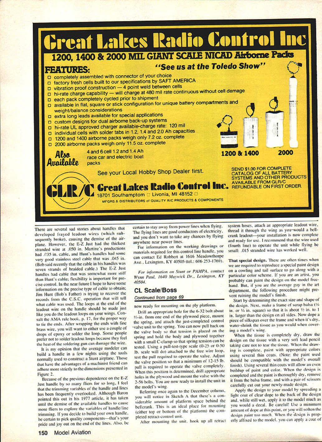
While I can't provide specific information on the Wilowski model installation, I can provide data on a Rom Air control valve unit I have been using very successfully in a Top Flite P-39 for several flying seasons. The same unit is now being installed in an SBD Dauntless by Pete Bianchini of Yonkers, NY. James also asked me to comment on the installation of retractable gear systems in general.
Although I would like to comply, there are too many variations of gear systems and types of planes for a general article to be very meaningful. However, the December column (which detailed how to strengthen the center section of a Control Line scale model) is a big step toward a solid bed in which to mount a retractable landing gear system. A little thought and ingenuity (along with manufacturer's installation instructions) should help to get your gear mounted. This article will detail the operation of a Rom Air control valve; the same basic idea can be applied to the operation of a switch for controlling a servo-operated retracting system.
Building the control valve unit
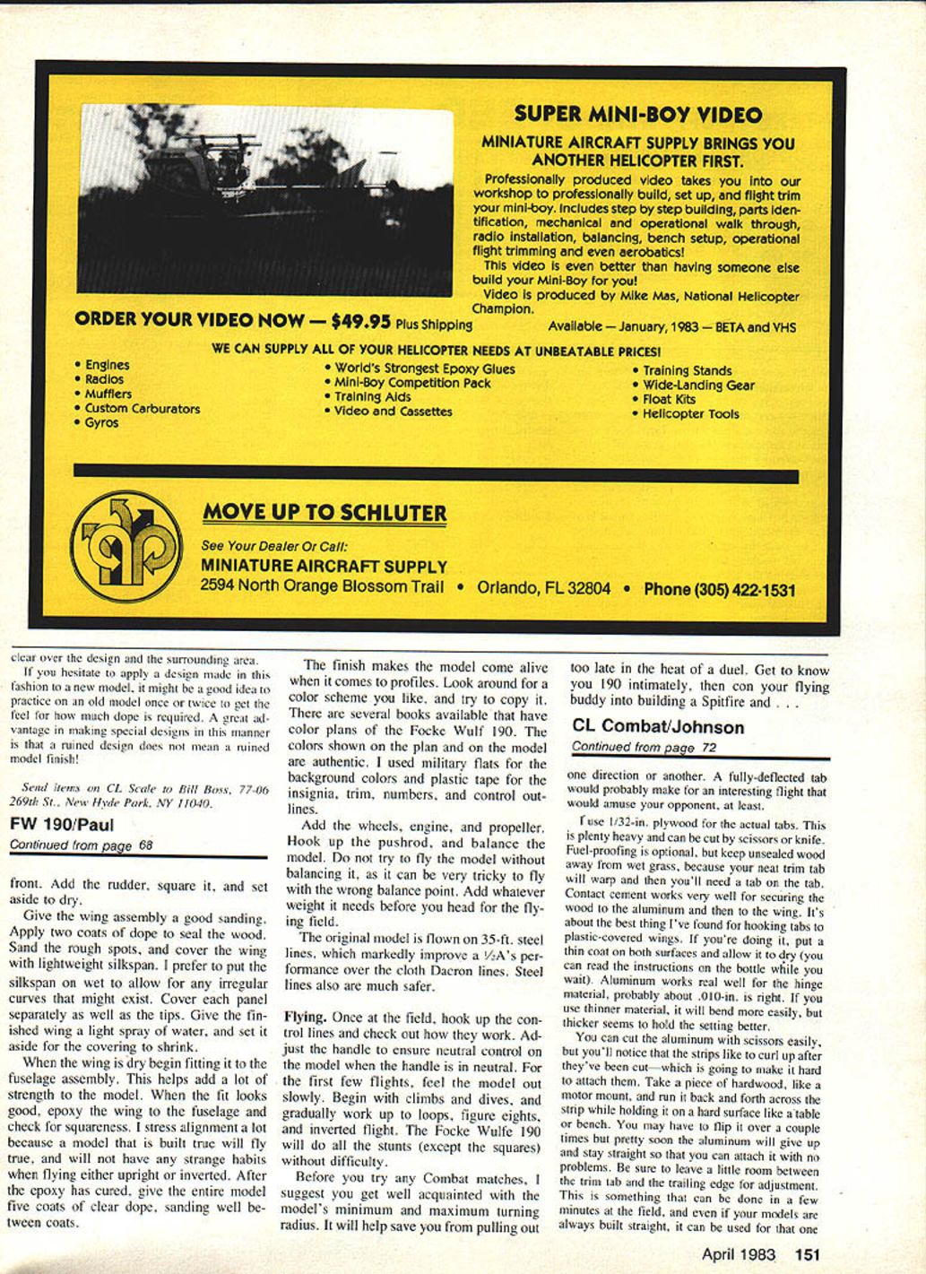
The accompanying photo (upper half) shows the Rom Air control valve unit in the completed state; the lower half of the picture shows the various parts before assembly. Items required for the unit are:
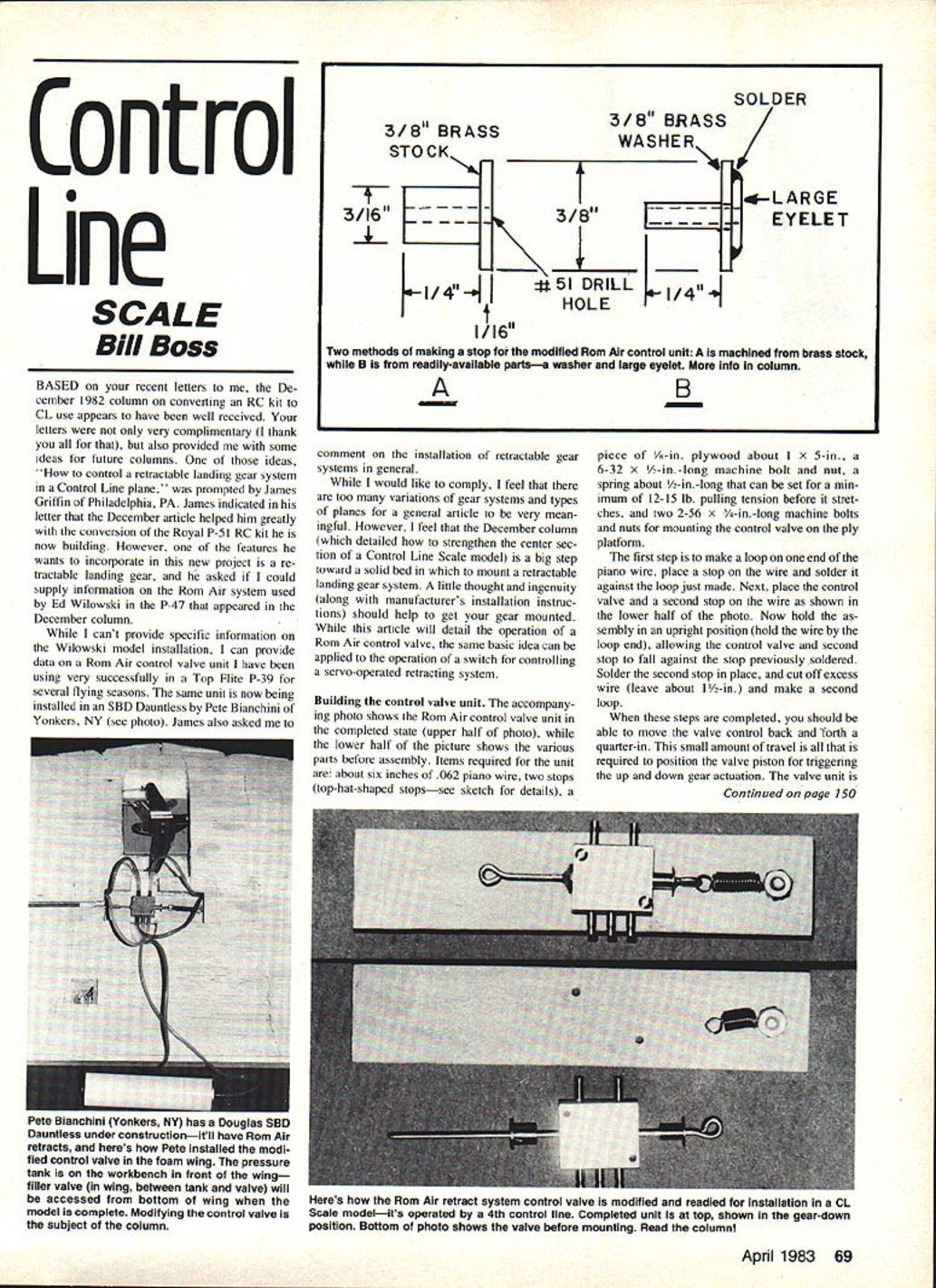
- ~6 in. of .062-in. piano wire
- Two stops (top-hat-shaped stops — see sketch for details)
- Piece of 5/8-in. plywood about 1 x 5 in.
- 6-32 x 1/2-in. machine bolt and nut
- Spring about 1/2 in. long that can be set for a minimum of 12–15 lb. pulling tension before it stretches
- Two 2-56 x 3/8-in. machine bolts and nuts for mounting the control valve on the ply platform
Assembly steps:
- Make a loop on one end of the piano wire. Place a stop on the wire and solder it against the loop you just made.
- Place the control valve and a second stop on the wire as shown in the photo.
- Hold the assembly upright (hold the wire by the loop end), allowing the control valve and second stop to fall against the stop previously soldered. Solder the second stop in place.
- Cut off excess wire (leave about 1-1/2 in.) and make a second loop.
When these steps are completed, you should be able to move the valve control back and forth about 1/4 in. This small amount of travel is all that is required to position the valve piston for triggering the up and down gear actuation. The valve unit is now ready for mounting on the ply platform.
Drill an appropriate hole for the 6-32 bolt about 1/8 in. from one end of the plywood piece, mount the spring, and attach the just-completed control valve unit to the spring. You can now pull back on the valve body so that tension is placed on the spring and hold the body and plywood together with a small C-clamp so that spring tension can be tested.
Using a pull-test type scale (0–25 or 0–50 lb. scale will do), attach the free wire loop and test the pull required to operate the valve. Adjust the valve position so that a minimum of 12–15 lb. pull is required to operate the valve completely. When this position is determined, drill the appropriate holes in the plywood and mount the valve with the 2-56 bolts. You are now ready to install the unit in the model's wing.
Referring once again to the December column, you will notice in Sketch A that there's a considerable amount of platform space behind the bellcrank. This is an ideal place for mounting (either top or bottom of the platform) the completed retract-control unit.
After mounting the unit, hook up all retract system hoses, attach an appropriate leadout wire, thread it through the wing as you would a bellcrank leadout — your installation is now complete and ready for use. I recommend that the wire used (the fourth line, i.e., the leadout) to operate the unit while flying be small: .015-in. stranded wire has worked well.
That special design
There are often times when we are required to reproduce a special paint design on a cowling and tail surface to go along with a particular color scheme. If you are an artist, you probably can paint the design on the model free-hand. But, if you are the average guy in the art department, the following procedure might prevent ruining the model's finish.
Procedure:
- Determine the exact size and shape of the design.
- Make a frame of scrap balsa (1/8 in. or 1/4 in. square) so that it is about 1/8 in. to 1/4 in. larger than the design on all sides.
- Dope a piece of silkspan (tissue) over the frame and, when it's dry, water-shrink the tissue as you would when covering a model's wing.
- When the tissue is completely dry, draw the design on the tissue with a very soft lead pencil, being careful not to tear the tissue.
- Paint with appropriate colors using several thin coats. (Note: the paint used should be compatible with the model's overall finish.) Using several thin coats will allow an even buildup of paint and color.
- When the design is completed and the paint is dry, carefully lift it from the balsa frame with a pair of scissors and carefully cut out your newly made design.
- Apply the design to your model by spreading a light coat of clear dope on the back of the design and, while still wet, apply it to the model much as you would a decal. Be careful — use a minimum amount of dope at this point, or you will soften the design paint too much.
- When the design is properly affixed to the model, apply a coat of clear dope over the design and the surrounding area.
If you hesitate to apply a design made in this fashion to a new model, it might be a good idea to practice on an old model once or twice to get the feel for how much dope is required. A great advantage in making special designs in this manner is that a ruined design does not mean a ruined model finish!
Send items on CL Scale to Bill Boss, 77-06 269th St., New Hyde Park, NY 11040.
Transcribed from original scans by AI. Minor OCR errors may remain.

