
CONTROL LINE SPEED
Dave Mark Box 371, Fenton MI 48430 E-mail: [email protected]
Introduction
When speed fliers discuss their hunt for more speed, the questions are usually engine related: Is my engine timed correctly? What can I do with my Dremel tool to generate more horsepower? Is the head deck height correct? Am I turning enough rpm?
Few modelers look at the model itself in their hunt for more miles per hour, but a change in model design improved one Speed flier’s time by 6 mph.
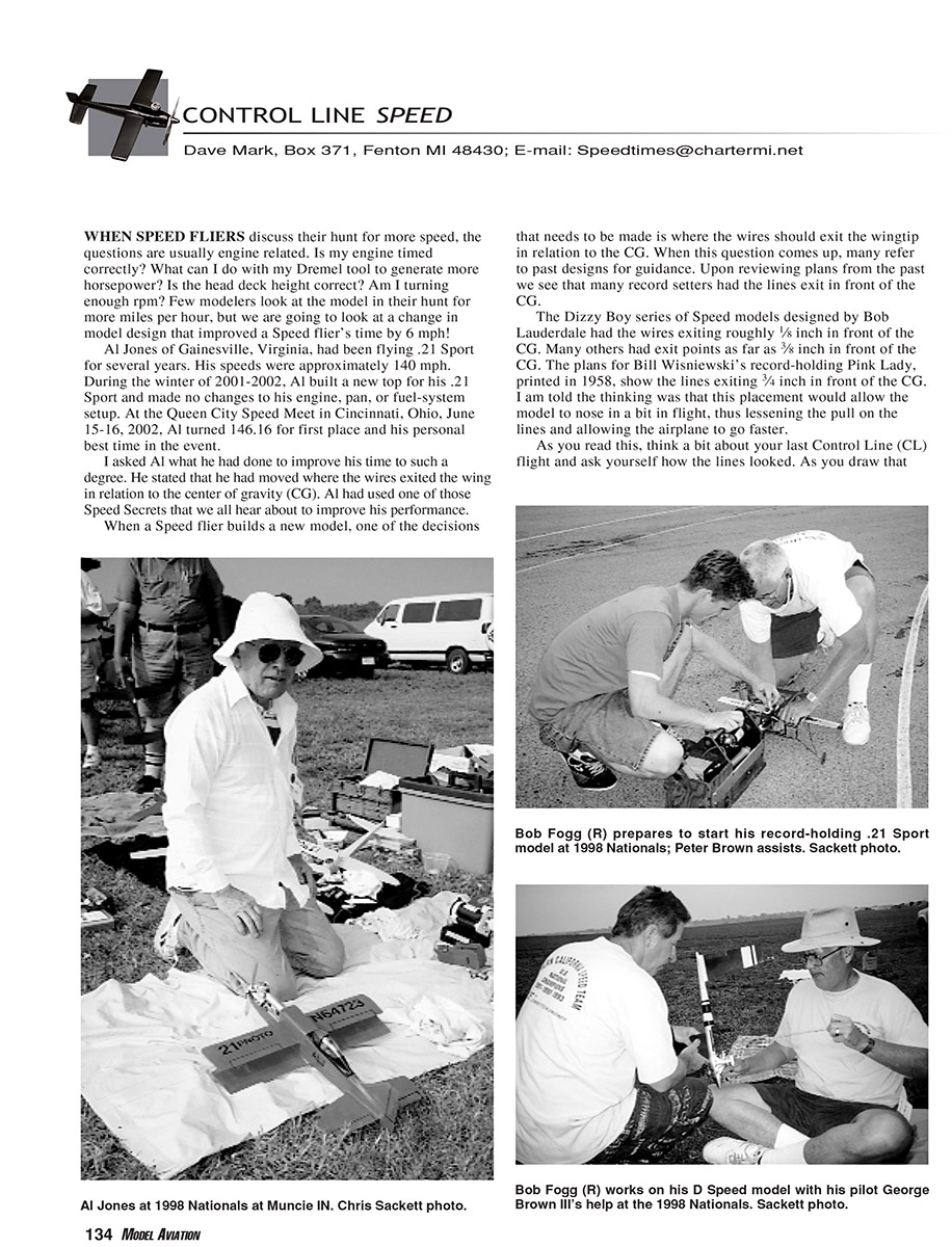
Al Jones of Gainesville, Virginia, had been flying .21 Sport for several years with speeds around 140 mph. During the winter of 2001–2002 he built a new top for his .21 Sport and made no changes to his engine, pan, or fuel-system setup. At the Queen City Speed Meet in Cincinnati, Ohio, June 15–16, 2002, Al turned 146.16 mph for first place and a personal best.
When asked what he had done to improve his time so much, Al said he had moved where the wires exit the wing in relation to the center of gravity (CG). This is one of those Speed "secrets" that can make a measurable difference.
Leadout placement: historical practice
When building a new model, one decision is where the lines should exit the wingtip relative to the CG. Reviewing old plans shows many record setters had the leadouts exit in front of the CG.
- Bob Lauderdale’s Dizzy Boy series had the wires exiting roughly 1/8 inch in front of the CG.
- Others had exit points as far as 3/8 inch in front of the CG.
- Bill Wisniewski’s record-holding Pink Lady (plans printed in 1958) shows the lines exiting 3/4 inch in front of the CG.
The thinking was that forward placement would allow the model to nose in a bit in flight, lessening the pull on the lines and allowing higher speed.
Why improper leadout placement hurts performance
Think of your last control-line flight: the lines form a graceful curve from the handle to the model, behind an imaginary straight line between handle and model. That curve plus a forward exit point causes the model to fly with the nose yawed inward relative to its path. The result is increased drag because a streamlined model is effectively flying sideways to the circular path.
A second effect is on the propeller. If you set a Speed model with a 24-inch wingspan over a straight line and move the inboard wingtip 3/4 to 1 inch toward the rear, the model yaws noticeably. From the top view, that yaw changes the effective pitch of the propeller blade on top (increasing) and the bottom blade (decreasing). A propeller filed and sanded for identical blade geometry loses much of its effectiveness when misaligned to the flight path.
Using Bob Fogg’s leadout program
Rather than guessing at placement, use the shareware program written by Bob Fogg to calculate the neutral leadout (zero yaw) position and other important parameters. Bob has solved many practical problems for Speed and Racing classes; his program is a useful tool.
The program consists of two files: leadout.exe and leadout.dat. Copy both into the same directory and start leadout.exe. A window with a green background appears with two data-entry boxes:
- Left box: enter wire diameter, line length, and select monoline or two-wire configuration.
- Right box: enter span of the inboard wing (half-span), model weight, and target speed.
Example inputs used here: Formula .40 model, 24-inch wingspan (12-inch inboard span), 26 ounces, target 162 mph.
As soon as the data are entered, the program calculates:
- Neutral leadout position for zero yaw angle
- Line pull
- Line yield strength based on 80% of ASTM A228 tensile strength of an undersize (-.0005) wire
- Wire factor of safety (yield/load)
- Wire Reynolds number
- Wire coefficient of drag
- Drag load in pounds
- Wire-drag horsepower
The program also notifies you if the wire will take a permanent set and displays the Factor of Safety in red if the combination of data entered is unsafe.
In our example the program reports the wire should exit the wing 0.702 inch behind the CG. If we change the inboard length to 15 inches, the program predicts 163.5 mph with the same horsepower. Playing with the program shows that the line is the greatest drag producer; this is why F2A models historically had very long inboard wings (to cover the wire) until regulations limited span to about 30 inches.
Practical effects and event considerations
Forward leadout placement often caused models to "come in" on takeoff and chase pilots around. A model set with the setback calculated by Bob’s program rolls off the dolly with a slight nose-out attitude, removing much of the launch anxiety.
However, some fliers of .21 Proto and Formula .40 events (timed from release for 14 laps) feel that a slight outward stance hurts the all-important first lap. They argue a quick first lap is critical and that any delay from nose-out stance is detrimental.
There is no perfect solution for all events. One possible approach is a device mounted in the wing to set the lines at zero setback for launch (zero yaw for the first lap) and then, when line pull indicates the model is up to speed, allow the lines to move back to the setback calculated by the program.
Availability, resources, and contacts
- Bob Fogg’s leadout program is shareware; if you use it, send a donation to Bob as listed in the program help file. The program is available on the Internet or from the North American Speed Society (NASS) for $5 to cover mailing and reproduction.
- Tom Wilk (Duluth, Minnesota) offers CD-ROMs of vintage Speed model plans:
- CD with more than 200 vintage Speed models designed from 1940 to 1958.
- CD with more than 125 models covering classic Speed from 1959 to present.
- CD with Goodyear and Team Racing designs.
- CDs are $10 each, postpaid in the U.S. Contact Steve Wilk of Eliminator Props at (763) 531-0604 to order.
- For more information about CL Speed, consider joining the North American Speed Society. Write to NASS at Box 371, Fenton MI 48430.
Please keep in mind that results may vary. If you use Bob’s program, consider sending the shareware donation as requested.
That’s it for now. I’ll be back in three months. Please send any pictures or requests for items you would like to see in the column. If you would like a reply, an SASE would be appreciated.
DM
Transcribed from original scans by AI. Minor OCR errors may remain.

