
Cowl Making 101
by Fred Randall
Custom-dress the front end of your model
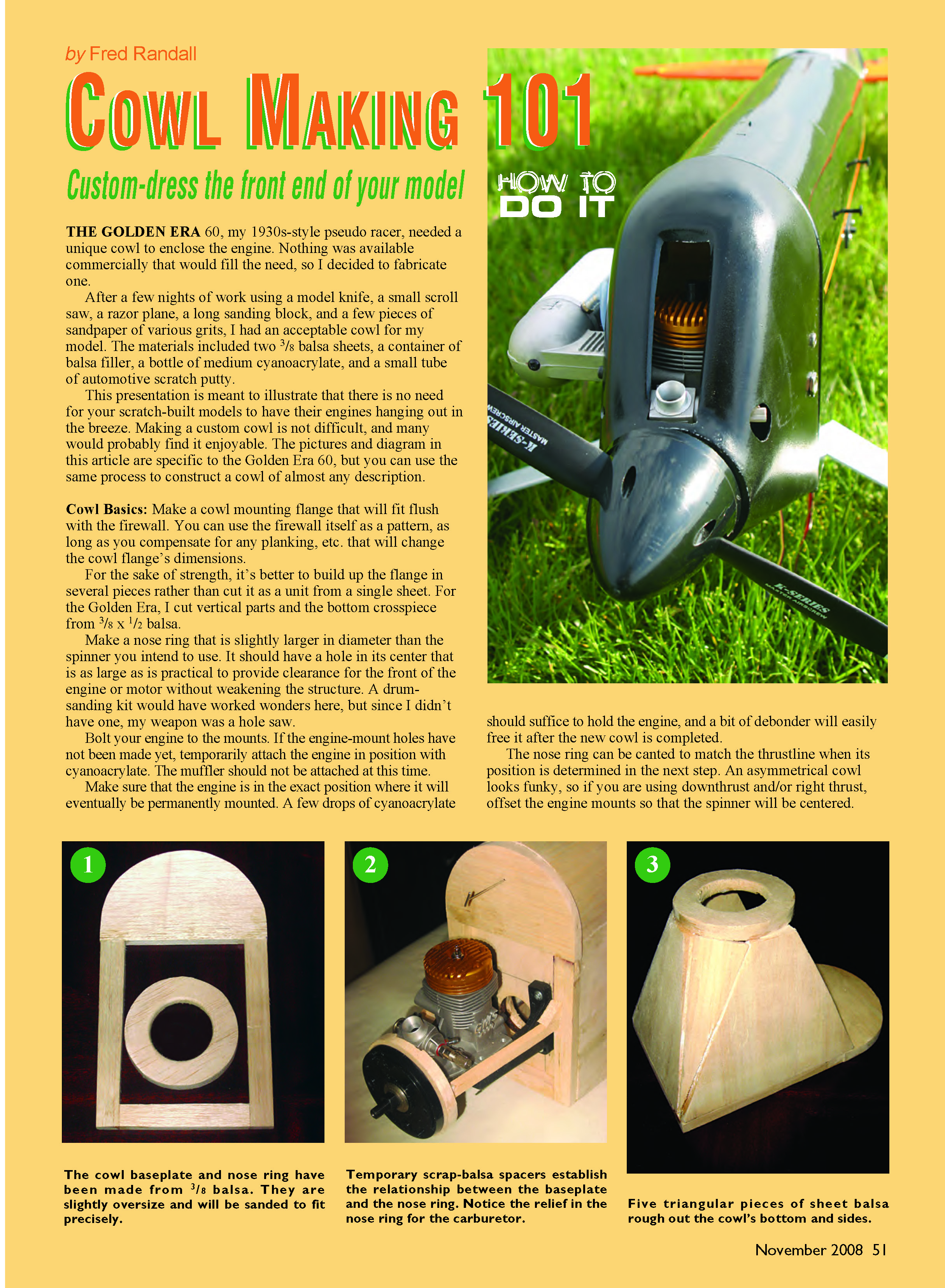
THE GOLDEN ERA 60, my 1930s-style pseudo racer, needed a unique cowl to enclose the engine. Nothing was available commercially that would fill the need, so I decided to fabricate one.
After a few nights of work using a model knife, a small scroll saw, a razor plane, a long sanding block, and a few pieces of sandpaper of various grits, I had an acceptable cowl for my model. The materials included two 3/8 balsa sheets, a container of balsa filler, a bottle of medium cyanoacrylate, and a small tube of automotive scratch putty.
This presentation is meant to illustrate that there is no need for your scratch-built models to have their engines hanging out in the breeze. Making a custom cowl is not difficult, and many would probably find it enjoyable. The pictures and diagram in this article are specific to the Golden Era 60, but you can use the same process to construct a cowl of almost any description.
Cowl Basics: Make a cowl mounting flange that will fit flush with the firewall. You can use the firewall itself as a pattern, as long as you compensate for any planking, etc. that will change the cowl flange's dimensions.
For the sake of strength, it's better to build up the flange in several pieces rather than cut it as a unit from a single sheet. For the Golden Era, I cut vertical parts and the bottom crosspiece from 3/8 x 1/2 balsa.
Make a nose ring that is slightly larger in diameter than the spinner you intend to use. It should have a hole in its center that is as large as is practical to provide clearance for the front of the engine or motor without weakening the structure. A drum-sanding kit would have worked wonders here, but since I didn't have one, my weapon was a hole saw.
Bolt your engine to the mounts. If the engine-mount holes have not been made yet, temporarily attach the engine in position with cyanoacrylate. The muffler should not be attached at this time.
Make sure that the engine is in the exact position where it will eventually be permanently mounted. A few drops of cyanoacrylate should suffice to hold the engine, and a bit of debonder will easily free it after the new cowl is completed.
The nose ring can be canted to match the thrustline when its position is determined in the next step. An asymmetrical cowl looks funky, so if you are using downthrust and/or right thrust, offset the engine mounts so that the spinner will be centered.
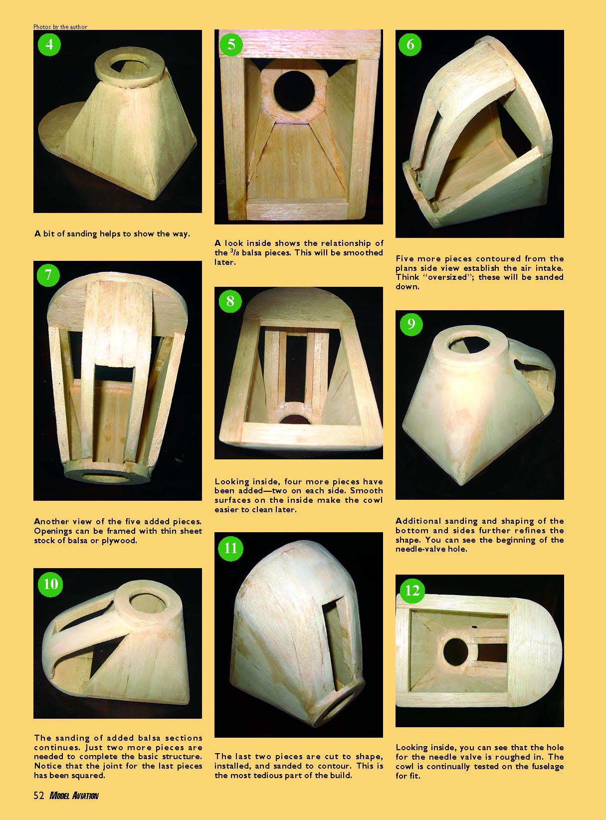
The cowl baseplate and nose ring have been made from 3/8 balsa. They are slightly oversize and will be sanded to fit precisely.
Temporary scrap-balsa spacers establish the relationship between the baseplate and the nose ring. Notice the relief in the nose ring for the carburetor.
Five triangular pieces of sheet balsa rough out the cowl's bottom and sides. A bit of sanding helps to show the way.
A look inside shows the relationship of the 3/8 balsa pieces. This will be smoothed later.
Five more pieces contoured from the plans side view establish the air intake. Think "oversized"; these will be sanded down.
Another view of the five added pieces. Openings can be framed with thin sheet stock of balsa or plywood.
Looking inside, four more pieces have been added—two on each side. Smooth surfaces on the inside make the cowl easier to clean later.
Additional sanding and shaping of the bottom and sides further refines the shape. You can see the beginning of the needle-valve hole.
The sanding of added balsa sections continues. Just two more pieces are needed to complete the basic structure. Notice that the joint for the last pieces has been squared.
The last two pieces are cut to shape, installed, and sanded to contour. This is the most tedious part of the build.
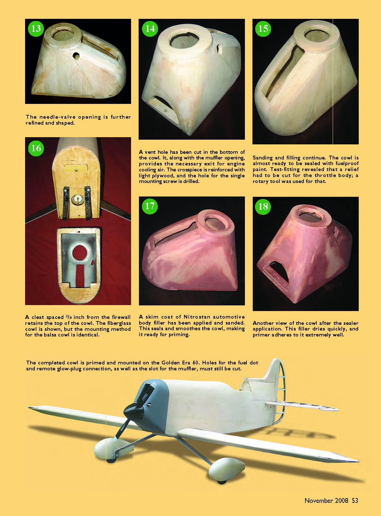
Looking inside, you can see that the hole for the needle valve is roughed in. The cowl is continually tested on the fuselage for fit. The needle-valve opening is further refined and shaped.
A vent hole has been cut in the bottom of the cowl. It, along with the muffler opening, provides the necessary exit for engine cooling air. The crosspiece is reinforced with light plywood, and the hole for the single mounting screw is drilled.
Sanding and filling continue. The cowl is almost ready to be sealed with fuelproof paint. Test-fitting revealed that a relief had to be cut for the throttle body; a rotary tool was used for that.
A cleat spaced 3/8 inch from the firewall retains the top of the cowl. The fiberglass cowl is shown, but the mounting method for the balsa cowl is identical.
A skim coat of Nitrostan automotive body filler has been applied and sanded. This seals and smoothes the cowl, making it ready for priming.
Another view of the cowl after the sealer application. This filler dries quickly, and primer adheres to it extremely well.
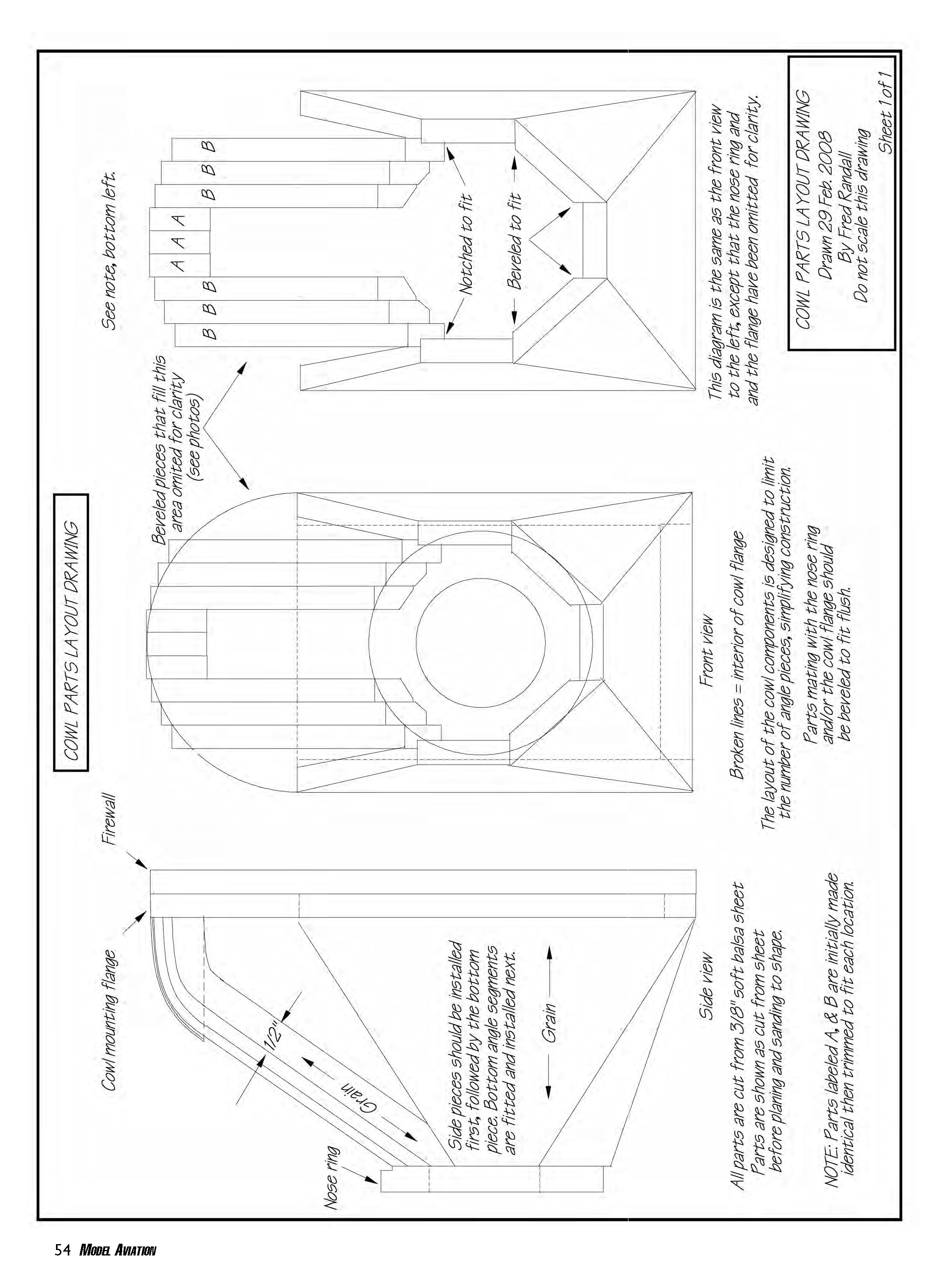
The completed cowl is primed and mounted on the Golden Era 60. Holes for the fuel dot and remote glow-plug connection, as well as the slot for the muffler, must still be cut. This diagram is the same as the front view to the left, except that the nose ring and the flange have been omitted for clarity.
Broken lines = interior of cowl flange.
The layout of the cowl components is designed to limit the number of angle pieces, simplifying construction. Parts mating with the nose ring and/or the cowl flange should be beveled to fit flush.
Front view
Side view
Beveled pieces that fill this area omitted for clarity (see photos).
All parts are cut from 3/8" soft balsa sheet. Parts are shown as cut from sheet; glue, clamp and sand to shape.
NOTE: Parts labeled A & B are initially made identical then trimmed to fit each location. Temporarily pin the cowl mounting flange in position on the firewall. Use scrap balsa to make standoffs for positioning the nose ring. These should be placed as far inboard as possible, so they don't interfere with the permanent parts to be installed later. Use T-pins to hold the standoffs until the exact nose-ring position can be determined.
Once satisfied, apply a few drops of cyanoacrylate to both ends of the standoffs and remove the assembly from the firewall. Leave the engine bolted or adhered to the mounts with cyanoacrylate until the cowl is finished.
Construction: Use the thickest lumber that is practical; it reduces the number of individual parts involved and eliminates the need to buy several sizes of balsa. I purchased two sheets of 3/8 x 4 x 36-inch soft balsa for my effort. If I hadn't made mistakes and was more careful arranging my cuts, I probably could have made the whole structure with a single sheet.
The diagram and photos are self-explanatory. So rather than a "cut this, glue that" description of the process, I'll continue with generalities that should apply to home-brewed cowls of almost any description.
The scrap balsa used to initially position the nose ring should be removed when the first permanent pieces are fitted and installed and the nose ring is secure.
The subject of this article uses five wedge-shaped pieces of 3/8 balsa sheet to rough out the sides and bottom. They facilitate the transition from square at the firewall end to round at the spinner. I installed these pieces first to provide a solid base for the nose ring.
Parts such as these, which need to be joined at an angle, should be cut somewhat oversize. Bevel the mating edges of the parts so that there is a reasonably tight fit. A razor plane makes this easy, and your careful work is rewarded by a much easier filling and sanding job later.
After each few pieces are added, rough-plane and/or sand them to their approximate shape. Don't wait until you have cyanoacrylate-glued all the parts together. It's much easier to keep the cowl symmetrical if you progress in small steps.
When a sculptor was asked how he went about chiseling a work of art, he replied, "It's simple, really. I just take a large piece of granite and remove any material that isn't a statue." Likewise, you should remove any balsa that isn't a cowl.
A razor plane and sandpaper can remove material that "isn't a cowl" at an almost alarming rate. However, unlike the sculptor, if you goof you can simply glue a piece of scrap balsa to the damaged area and then take a few more swipes with the sandpaper.
You can expect to do some finish-shaping with balsa filler. Several good products are available at a reasonable cost. Slightly dampen the balsa surface, and the filler will adhere better. The secret to good results with filler is to use several thin applications and allow them to harden thoroughly before attempting to work them.
I highly recommend applying a final, allover coat of automotive finishing putty before priming. Use a plastic applicator to spread it thinly over all surfaces. The putty dries to a much harder surface than balsa, and it should be sanded with fine wet or dry sandpaper. When you're finished, the surface will be ultrasmooth and won't soak up primer like a sponge.
The putty is fuelproof and accepts almost any kind of paint or primer. I used Nitrostan scratch filler. You can get it, or a similar product, at any consumer auto-parts store.
I dislike the look of visible screws attaching a cowl to a model's fuselage. The method shown to solve this problem can be applied to commercial units, and even ARFs.
A photo of a fiberglass cowl using this type of mount is included. Make a flange of balsa or light plywood, and epoxy it inside the supplied cowl. Notch the flange to engage a cleat secured to the firewall.
With its position established, a single screw concealed at the bottom attaches the cowl to your airplane. It's simple, it's secure, and there are no visible screws to mar the appearance.
Cowl Making 101
Fred Randall
As pieces were fitted to the structure, I found that I had to cut away material inside to provide clearance for the throttle body. This included a notch in the nose ring for the air intake. I also had to provide an opening for the needle valve. The use of a rotary tool is indicated for cutting reliefs in the cowl interior.
When I mounted the muffler, I would have to use an exhaust extension for it to clear the fuselage. Exhaust extensions (such as those by Du-Bro) are made so that they can be cut to any length, so I band-sawed a standard extension to position the muffler exactly where I wanted it.
The engine I used had no provision for installing the muffler screws from the opposite side of the engine, and the provided capscrews were not long enough to go through both the muffler flange and the exhaust extension. I found a simple solution.
I installed the proper-length studs in the engine and secured the muffler/extension assembly with binding nuts. I used blue Loctite on both the studs and the nuts.
I wanted the opening for the muffler to be a simple slot, so I removed the pressure fitting from the muffler, put a small screw in the hole, and sealed it with high-temperature silicone. Then I drilled and tapped a hole in the muffler directly behind the engine exhaust port and reinstalled the pressure fitting. Making the slot in the cowl was the final operation before painting.
With the cowl mounted, I needed a fuel fitting and a glow-plug connector. Good remote glow-plug jacks and fuel "dots" are available from several sources.
Since balsa is relatively fragile, I drilled mounting holes in a small square of 1/8 light plywood and affixed the plug and fuel accessories to it. After drilling access holes for the connectors in the balsa, I epoxied the plywood piece inside the left rear cheek of the cowl. I drilled a hole through the balsa and the plywood between the fittings, and I installed a 6-32 screw, nut, and washers.
Have fun fabricating your new cowl, and E-mail me pictures of the result. If you have a building problem I didn't cover, I'd like to hear about that too.
Fred Randall [email protected]
Sources:
Nitrostan (scratch filler) (800) 772-3675 www.nitrostan.com/spotputt.html
Du-Bro (exhaust extension) (800) 848-9411 www.dubro.com/hobby
Transcribed from original scans by AI. Minor OCR errors may remain.

