
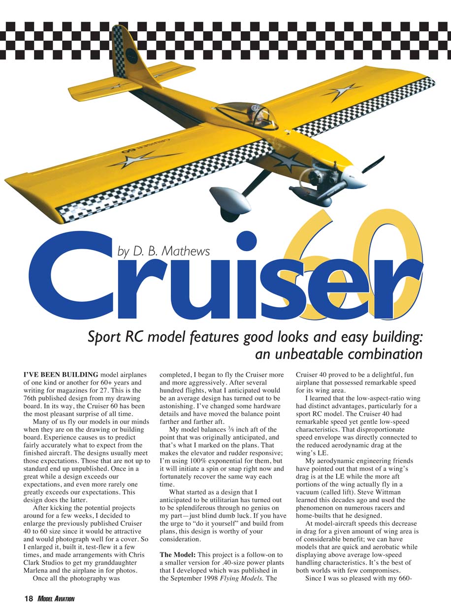
Cruiser 60
by D. B. Mathews
Sport RC model features good looks and easy building: an unbeatable combination
I've been building model airplanes of one kind or another for 60+ years and writing for magazines for 27. This is the 76th published design from my drawing board. In its way, the Cruiser 60 has been the most pleasant surprise of all time.
Many of us fly our models in our minds when they are on the drawing or building board. Experience causes us to predict fairly accurately what to expect from the finished aircraft. The designs usually meet those expectations. Those that are not up to standard end up unpublished. Once in a great while a design exceeds our expectations, and even more rarely one greatly exceeds our expectations. This design does the latter.
After kicking the potential projects around for a few weeks, I decided to enlarge the previously published Cruiser 40 to 60 size since it would be attractive and would photograph well for a cover. So I enlarged it, built it, test-flew it a few times, and made arrangements with Chris Clark Studios to get my granddaughter Marlena and the airplane in for photos. Once all the photography was completed, I began to fly the Cruiser more and more aggressively. After several hundred flights, what I anticipated would be an average design has turned out to be astonishing.
I've changed some hardware details and have moved the balance point farther and farther aft. My model balances 3/8 inch aft of the point that was originally anticipated, and that's what I marked on the plans. That makes the elevator and rudder responsive; I'm using 100% exponential for them, but it will initiate a spin or snap right now and fortunately recover the same way each time. What started as a design that I anticipated to be utilitarian has turned out to be splendiferous through no genius on my part—just blind dumb luck. If you have the urge to "do it yourself" and build from plans, this design is worthy of your consideration.
The Model
This project is a follow-on to a smaller version for .40-size power plants that I developed and published in the September 1998 Flying Models. The Cruiser 40 proved to be a delightful, fun airplane that possessed remarkable speed for its wing area.
I learned that the low-aspect-ratio wing had distinct advantages, particularly for a sport RC model. The Cruiser 40 had remarkable speed yet gentle low-speed characteristics. That disproportionate speed envelope was directly connected to the reduced aerodynamic drag at the wing's leading edge. My aerodynamic engineering friends have pointed out that most of a wing's drag is at the leading edge while the more aft portions of the wing actually fly in a vacuum (called lift). Steve Wittman learned this decades ago and used the phenomenon on numerous racers and home-builts that he designed.
At model-aircraft speeds this decrease in drag for a given amount of wing area is of considerable benefit; we can have models that are quick and aerobatic while displaying above-average low-speed handling characteristics. It's the best of both worlds with few compromises.
Since I was so pleased with my 660-square-inch 40-size version, I enlarged the model to approximately 800 square inches and powered it with a .60 engine. The result is a model that retains the smaller version's virtues and features much improved visibility and smoother flying, especially in moderate winds. The Cruiser 60 is special in every way. It flies much faster than a similarly powered model of equal wing area. Horizontal and vertical performance are well out of proportion to its slow-speed handling. It is a fully aerobatic design with trainer-like landings and takeoffs.
Not only that, but the thing is certainly more attractive than many other midwing designs that are currently flown. The Cruiser 60's fuselage is narrower than usual for two reasons: a side-mounted engine's muffler will easily clear the fuselage without tedious structure removal, and newer modern servos and receivers simply do not require the fuselage width formerly needed.
Construction
All hardware and material used in this project are standard hobby-shop stock, or at least easy to order. The only special tools needed are a jigsaw; a 12-inch-long, 1/4-inch-diameter drill bit; and a carbide cutter in a hand grinder, but one could get by without them.
The principle adhesive is medium cyanoacrylate; thin is used for the hinges and epoxy is used for the wing joint and firewall installation. Cover the Cruiser 60 wing with a high-heat Mylar such as MonoKote or UltraCote; other materials may allow excessive flex and twist.
The slot-in-tab light-plywood fuselage construction requires a bit more work for the scratch builder, but it results in an easy-to-assemble, straight and true fuselage. The best way to make the lightening cutouts is to drill 1/4-inch holes in a couple spots in each cutout, thread the jigsaw blade through the holes, and cut both fuselage sides out stacked.
Alternatively, the sides can be firm 1/8-inch balsa left unslotted aft of the wing trailing edge. In this instance I'd still use a light-plywood (poplar) doubler and assemble the fuselage by drawing a midline on the top block and formers. The formers can be adhered to the top exactly on the marks and truly vertical, and then the sides can be pulled together against them.
Model designers have used the four-spar wing repeatedly, which is a testament to its ease of construction, freedom from warps, and lightness. The semisymmetrical airfoil will build flat on the building board without the need for tabs or special fixtures.
There are several methods for transferring parts patterns to the appropriate wood. My favorite is to make photocopies from the plans, cut them slightly oversized, and adhere them to the wood with a glue stick. You can then cut the parts, sand them to the final outline, drill all holes, and then peel off the paper.
You can create larger patterns, such as the fuselage sides, by placing sheets of carbon paper between the plans and the sheet wood. Use plastic-headed map pins to hold the three layers in alignment. When you do this, use a straightedge for every line possible and an adjustable french curve elsewhere; don't try to freehand anything you can draw with an edge.
Wing
Fabricate the ribs using the photocopy pattern technique. Only two rib patterns are used in the wing. Pin this plywood pattern onto a stack of rectangular balsa blanks and rough-cut with a saw. Sand in the final outline. I like to cut the spar slots undersized and then use a tool—made from scrap spar with aluminum-oxide paper glued onto its bottom edge with cyanoacrylate—to final-shape the slots.
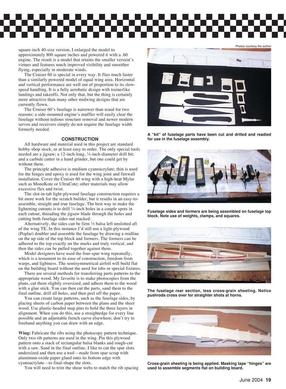
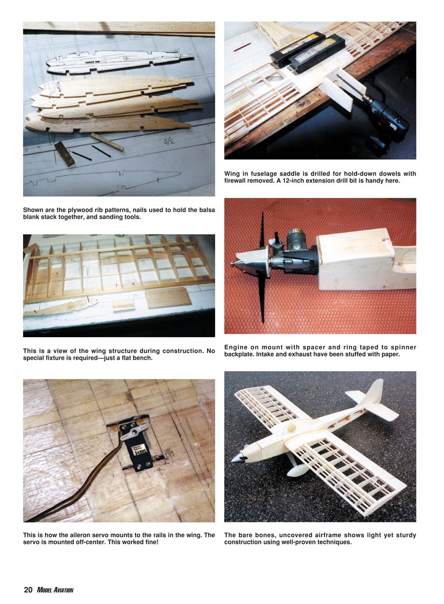
You will need to trim the shear webs to match the rib spacing. Shown are the plywood rib patterns, nails used to hold the balsa blank stack together, and sanding tools.
Wing in fuselage saddle is drilled for hold-down dowels with firewall removed. A 12-inch extension drill bit is handy here.
This is a view of the wing structure during construction. No special fixture is required—just a flat bench.
Engine on mount with spacer and ring taped to spinner backplate. Intake and exhaust have been stuffed with paper.
This is how the aileron servo mounts to the rails in the wing. The servo is mounted off-center. This worked fine!
The bare-bones, uncovered airframe shows light yet sturdy construction using well-proven techniques.
Lay the ribs over the drawings and cut off the excess. Score the center-section ribs for later punch-out of the slot into which the dihedral brace will be inserted. I drill 1/16-inch holes, leaving enough wood to hold things together.
Place waxed paper over the plans, and position and pin the trailing-edge sheet, bottom spars, and center-section sheeting, using ribs to correctly position everything. Using the shear webs and a dihedral gauge, position the ribs and adhere them. Add the top spars and the upper center sheeting and leading edge. Leave one part of the center-section sheeting off until you have joined the wings.
Repeat this process for the opposite wing, remove and sand off any lumps or bumps, and then carve the leading edge to the outline shown on the plans.
Block up the outside tip of one wing panel 3/4 inch, place the inboard end parallel to a table edge, and use a coarse sanding block to sand in the dihedral angle. It may be necessary to saw off the spar ends to match.
Repeat this process for the opposite wing, and then trial-fit the center joint. Some touch-up sanding may be needed to obtain a nice, tight joint.
Punch out the previously scored center rib slots and trial-fit the dihedral brace. Trim and adjust to obtain a solid fit between the wing halves with the dihedral blocked in.
With one panel pinned flat and the other blocked up to twice the dihedral, smear long-cure epoxy (not the five-minute variety) onto both root ribs, the slots, and the plywood gusset, then join and allow to cure. Install the last of the center-section sheeting.
You can develop wingtips from the two cutoff rear ends of the fuselage top if they were carefully trimmed off. Pin the scrap in place and use a pencil to draw an outline of the tip rib onto them. Remove the scrap, cut oversize, and then sand to match the tip rib and round the outside edges.
Cut the servo well and install the servo dowels after applying the fiberglass tape. Cut the sections of sheet that will contain the aileron servo horns. Slot them at their faces with a knife, and then sand in the slot using the threaded section of the horns. Cut clearance holes for the vertical portion of the horns. The horns exit the bottom of the wing on this design and should be as close together at the midline as possible.
Position and adhere the center aileron horn blocks to the wing trailing edge using cyanoacrylate glue. A bit of Vaseline flowed between the wire and tube will prevent them from getting stuck.
Sand the aileron blocks to match the center-section. Fill the holes for the vertical portion of the aileron horns with modeling clay to prevent epoxy from running into them when you are fiberglassing the wing center-section.
My preference for this step is to use Sonic-Tronics' 6-inch-wide fiberglass tape. Spray a precut length with 3M Spray-Ment and then lay the tape on, starting in the middle of the bottom. Pull and rub out any wrinkles, and then brush thinned epoxy through the weave. Don't use more epoxy than is required to fill the weave so you don't add excessive weight. Trowel the epoxy into the fiberglass with a scrap of wood until it all looks wetted.
After the epoxy has cured, measure and mark a hole for the aileron servo. I've been mounting the servo off-center to avoid cutting into the center ribs. I have done this on my last three projects and am unable to tell any difference in flight.
Cut through the epoxy/fiberglass and the underlying balsa to create a hole that will just clear the servo and its wires.
Measure another set of cutouts for 3/8 x 3/8-inch basswood strips. These should extend through the center ribs and outboard at least a half inch. You can make this cutout with a knife, but a carbide cutter in a hand grinder is certainly speedier. The servo rails should sit flush with the balsa/epoxy surface. You can adhere them with cyanoacrylate.
Trial-fit the aileron servo and its hardware, and cut off the excess horn below the connectors for clearance of the fuselage servos. Create two overlength sections of 3/8-inch balsa for the ailerons. Mark a midline on the rear, and carve them to an airfoil shape using a razor plane and sandpaper blocks. Cut off enough for the fixed portion at the tips, and adhere to the trailing edge with cyanoacrylate. Trim the remainder to fit, with roughly 1/8 inch clearance on both ends.
Sand in the usual hinge-line bevel, and then slot the aileron and drill for the horns per the instructions for the elevator. Trial-fit and adjust the hot hinges.
Fuselage
Using the previously mentioned carbon-paper transfer system, develop a fuselage side, a doubler, and the formers. Nail another section of wood under the first, and cut out the sides and doublers in pairs. Sand all edges flush with each other. Be sure to mark one as left and the other as right.
Join the doubler to the side with troweled epoxy (the five-minute variety is okay here). Weight these left and right sides while the epoxy is curing. Check the fit of all formers in slots; they should fit snugly but not require force to seat.
Mark a full-length midline on the top block and on the formers. Nail down the top block, and then position the formers to match the midline. Do not cut the upper wing-saddle panel loose from the fuselage sides until the fuselage construction is nearly finished.
Use masking tape and clamps to preassemble the fuselage, and then check for squareness in all planes. Position the center-section over the top block, and then flow medium cyanoacrylate along the joints. The landing-gear block and its triangular braces should be installed with epoxy. Do not adhere the firewall permanently until the wing has been trial-fit and the dowel holes have been drilled!
Draw the tail post and its filler together over the midline mark, and then add the rear formers, maintaining squareness and alignment at all times. Some weight will help in this step. When you are satisfied, adhere everything with cyanoacrylate.
As an aid in later sanding and shaping, place a scrap of 3/8-inch balsa in the aft portion of the elevator slot and in the rudder slot using a drop or two of cyanoacrylate. The 1/8-inch triangular-stock top corner fillers can easily be cut to the proper length using the bottom former spaces as a cutting guide, then adhered to the corners.
In the past I've had major problems trying to bend a full-length section and adding the formers with triangular cutouts. I could never get the triangular stock to lay flat when it is also bent.
Adhere the tail-wheel bracket piece, and then cover the bottom rear with cross-grain basswood. I prefer hinging the sections flat on a building board with masking tape, flowing cyanoacrylate onto the edges, and then installing the unit onto the fuselage bottom. The forward section is covered with cross-grain light plywood joined with the balsa over a scrap of 3/8-inch balsa strip. Again, do not adhere it to the firewall.
Rough-cut the bottom sheeting to an approximate match to the fuselage side. Using an X-Acto #26 blade or a sharp knife, rough-cut the fuselage top block. Be conservative here; some of that 3/8-inch sheet scrap can be used for the tail feathers.
Remove the fuselage from the building board, and sand the top and bottom to a rough outline fit at this time. You will contour everything after assembly. See the cross-section view on the plans.
Cut the wing-saddle hatch loose. Mark cut lines on the top block and the sides, and then cut through them with a razor saw. Add interior formers and sand for a smooth, sliding fit between the removable hatch and the fuselage formers. Allow enough space for the covering material. Cut into the previously prepared slots in the various formers, and add the basswood hold-down blocks. Epoxy the wing hold-down and its triangular reinforcements to the fuselage side.
For a neat joint between the wing and the hatch, pencil-mark any area that may be holding the hatch off and trim this area using a shoemaker’s file. A shoemaker’s file has medium and coarse textures and a flat and curved side.
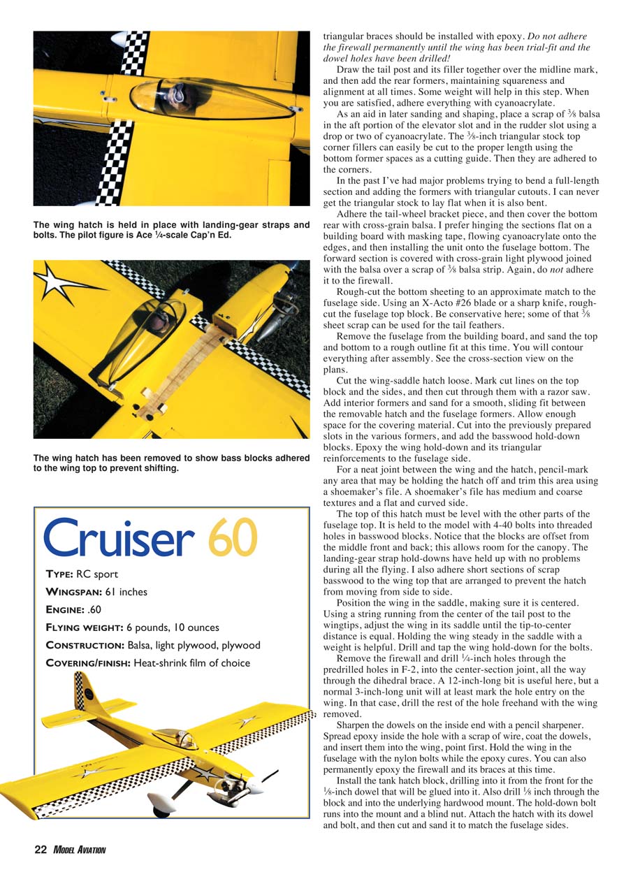
The top of this hatch must be level with the other parts of the fuselage top. It is held to the model with 4-40 bolts into threaded holes in basswood blocks. Notice that the blocks are offset from the middle front and back; this allows room for the canopy. The landing-gear strap hold-downs have held up with no problems during all the flying. I also adhere short sections of scrap basswood to the wing top that are arranged to prevent the hatch from moving from side to side.
Position the wing in the saddle, making sure it is centered. Using a string running from the center of the tail post to the wingtips, adjust the wing in its saddle until the tip-to-center distance is equal. Holding the wing steady in the saddle with a weight is helpful. Drill and tap the wing hold-down for the bolts.
Remove the firewall and drill 1/4-inch holes through the predrilled holes in F-2, into the center-section joint, all the way through the dihedral brace. A 12-inch-long bit is useful here, but a normal 3-inch-long unit will at least mark the hole entry on the wing. In that case, drill the rest of the hole freehand with the wing removed.
Sharpen the dowels on the inside end with a pencil sharpener. Spread epoxy inside the hole with a scrap of wire, coat the dowels, and insert them into the wing, point first. Hold the wing in the fuselage with the nylon bolts while the epoxy cures. You can also permanently epoxy the firewall and its braces at this time.
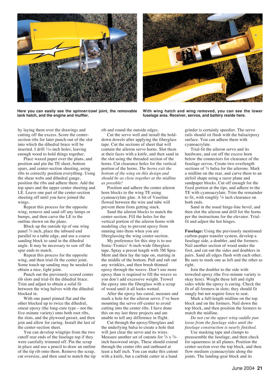
Install the tank hatch block, drilling into it from the front for a 1/8-inch dowel that will be glued into it. Also drill 1/8 inch through the block and into the underwing hardwood mount. The hold-down bolt runs into the mount and a blind nut. Attach the hatch with its dowel and bolt, and then cut and sand it to match the fuselage sides.
Specifications
- Type: RC sport
- Wingspan: 61 inches
- Engine: .60
- Flying weight: 6 pounds, 10 ounces
- Construction: Balsa, light plywood, plywood
- Covering/finish: Heat-shrink film of choice
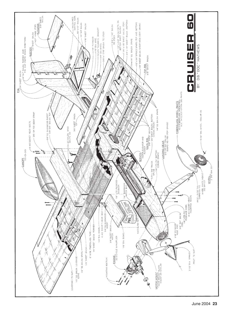
Plans and Part Labels (notes extracted from the diagram sheet)
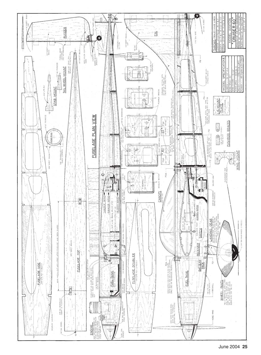
- Fuselage plan view:
- Fuselage side
- Fuselage top
- Fuselage doubler
- Rudder
- Elevator
- Stabilizer mount
- Tail wheel mount
- Engine
- Fuel tank
- Canopy
- Battery / receiver
- Landing gear
- Wheel pants
- Nose ring
- Propeller
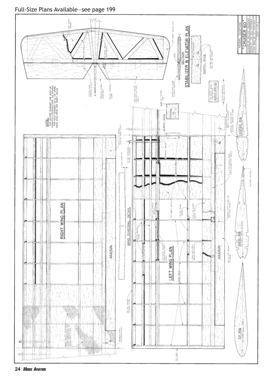
- Left wing plan:
- Center rib
- Aileron
- Tip rib
- Right wing plan:
- Aileron
- Tip rib
- Miscellaneous plan labels/details:
- Pushrod braces
- Wing mount
- Fillet / fairing locations
- Firewall / mounting doubler
- Hatch / tank access
- Control horn locations
- Servo mounts
- Other plan views mentioned:
- Stabilizer & elevator plan
- Right wing plan
- Wing dihedral detail
- Left wing plan
- Aileron, tip rib, center rib callouts
(End of primary-article text from the plans/diagram sheet.)
Cowl
Screw the engine to its mount, tack-glue a filler to hold the nose ring onto the engine, and then tack-glue the ring to the back of the spinner.
Use the fuselage side view to rough-cut a 3/8-inch block for the cowl side. Measure the difference between the front and rear using the top view, block up one end that amount, and, using the table-edge technique, sand in the appropriate bevel. Turn the block over and sand the other bevel the same way.
Check for a good fit between the block and the firewall and spinner ring. Go slowly, sanding a little at a time until they join nicely, and then cut the top and bottom of the block the same way. Once they all fit and leave some room for shaping, adhere the whole assembly in place with cyanoacrylate. You may need to fill the corners on the front with scraps of 3/8-inch triangular stock to reinforce them.
Remove the engine, then carve the blocks to a pleasant shape that is flush with the firewall and spinner ring. This step will go faster if you use that #26 X-Acto blade or sharp knife for rough shaping. Follow that with 100-grit sandpaper, and work your way down to 220 grit. After you have shaped the cowl, fill the interior joints with epoxy.
Sand everything into a smooth blend from the front to the rear. Do this with the wing saddle installed with 4-40 bolts into the threaded blocks and the tank hatch installed. Fill holes and dings with one of the microballoon fillers, and then fine-sand the entire unit with 400-grit sandpaper.
Tail
These are straightforward sheet surfaces. However, if the engine system to be used weighs less than 25 ounces complete, you may want to lighten the tail by using a sandwich construction for the stabilizer. To do that, make a 1/4-inch-strip interior covered top and bottom with 1/16-inch balsa. Otherwise, use medium C-grain sheet. The model tends to be slightly nose-heavy with most .60-size engines, so the needed tail weight might as well be in the structure.
The forward part of the fin has the grain running horizontal for added strength. This part does not sit in the fuselage top slot either. Join sheet sections on a flat surface. The elevator joiner wire is easier to get right if it is installed before the elevator halves are cut apart. It is also helpful to drill the horn holes slightly oversized and fill the gaps with epoxy.
Sand the perimeters of these structures round at the leading edge and with an airfoil-type taper toward the rear. Hinge lines are beveled. Trial-fit the hinge before final sanding.
Covering and Finish
The curve of the fin, stabilizer, and wingtips are easier to cover if you seal a strip of covering material approximately 1/2 inch wide on the perimeters before applying the major sections. This is also true for the ends of the ailerons and their matching cutouts at the wing trailing edge.
Seat these strips along the midline, and then pull them out and down while applying heat, trying for as much coverage without wrinkles as possible. Trim off the wrinkled areas, then proceed using the manufacturer's recommended technique.
Cover the parts separately and then assemble them. The covering material will go further if you cover the largest sections first. I much prefer to seal the hinge lines. This greatly improves the control surfaces' efficiency, improving handling and responsiveness while greatly reducing the potential for flutter. My pet method is to adhere the covering along the leading edge, stretch it, and seat it to the rear of the fixed surface, adhere it to the tips, and cut through the covering for the joint between the edges that will move and those that don't.
Deflect the movable surface away from the covering, then tack it along the face edge of the hinge line. Stretch the plastic out to the trailing edge and seal. Seal the other borders, and run a trim iron along the hinge line again with the surface deflected. Repeat for the opposite side of the panel, and then use a heat gun to shrink everything tight. Try to avoid overdoing the heat on the hinge lines. The net result is sealed surfaces that are relatively easy to develop yet extremely effective. They will reduce the required throws for any given maneuver by roughly half compared to open hinge lines.
I covered the model in the photos with Bright Yellow UltraCote, painted the wheel pants with Rust-Oleum, and the graphics are Sig A&B vinyl stick-ons. I left the metal gear natural and polished it to a mirror finish with Happich Semichrome (available at motorcycle shops). I painted the Du-Bro gear with Rust-Oleum.
Last Details
I prefer Sullivan tail-wheel brackets, but I could not find one locally. The Sig aluminum gear fits nicely but is a bit short on propeller clearance when the model is flying from long grass. The Du-Bro fiberglass-filled Super Strength Landing Gear (part number 789) does provide an extra inch of ground clearance.
Fuel-proof the interior of the engine and tank compartments with two coats of thinned epoxy. Smear some of the excess into the forward areas of the radio compartment just in case. The model looks nice if the interior of the engine room is painted; I used K&B Ultrapoxy. It is best to do these steps after the model is covered.
The low-rate control-surface deflections specified on the plans will provide nicely controlled loops and rolls, but they are insufficient for violent snaps, etc. However, in high rate, hang on!
I prefer solid wire-in-tube connections for the control hookups. I use Sullivan Solid Steel Rod Type Golden Rods (part number S511) 2-56 threaded rods with a solder link on the servo end and a threaded clevis on the surface end. These are run through pushrod guides as shown on the drawings, trying for as close to a straight shot as possible. The rudder rod is attached to the outside of the left servo, the elevator to the right side of the center servo, and the throttle cable to the outside of the right servo.
You will need to trim the canopy. Remove all but approximately 1/8 inch of the horizontal flash with canopy scissors. Place the canopy on a flat surface, and score the outline using a tool made from a #11 X-Acto blade cyanoacrylate glued between two layers of 1/16-inch scrap plywood. Hold the tool flat against the work surface, and gently move it around the canopy’s perimeter. Use canopy scissors on the sharp curves fore and aft, and crack and peel the rest.
Adhere the canopy to the hatch by marking its outline and then removing roughly 3/32 inch of the covering to match. Attach the canopy with Weld-On RC/56 canopy glue, and use trim tape to hide the joint.
By placing the battery pack under the tank, the receiver on the floor, and the servos well down in the fuselage rear (but with working room forward of the wing mount), my prototypes are coming out a tad nose-heavy. If you somehow create a model that hangs tail-low when two fingers are placed at the marked balance point, add nose weight. Do not attempt to fly this model tail-heavy!
In the Air
The Cruiser 60 is attractive for a midwing design, somewhat resembling a full-scale Goodyear racer, but appearance is only skin deep. Beneath that sharp-looking exterior lies a surprising model. Its low aspect ratio and comparatively thin airfoil produce a model with an astounding speed range. In low throttle it behaves much like an aileron trainer, producing well-controlled slow landings, gentle "down the pipe" takeoffs, and no vices when flown slowly.
Turn on the juice, and wow! The Cruiser 60 moves like smoke. Aerobatics are limited only by the flier's skills. The model will roll from one end of the field to the other and do rolling circles, wild-looking horizontal and vertical snap rolls, spin flat, do lovely vertical 8s and vertical Cuban 8s, and knife edge with little coupling, all in a controlled manner.
This model does not "jump and flit"; it flies like an airplane! Not only that, but it looks good. So build yourself one and fly it for fun.
D.B. Mathews 909 N. Maize Rd., Townhouse 734 Wichita, KS 67212
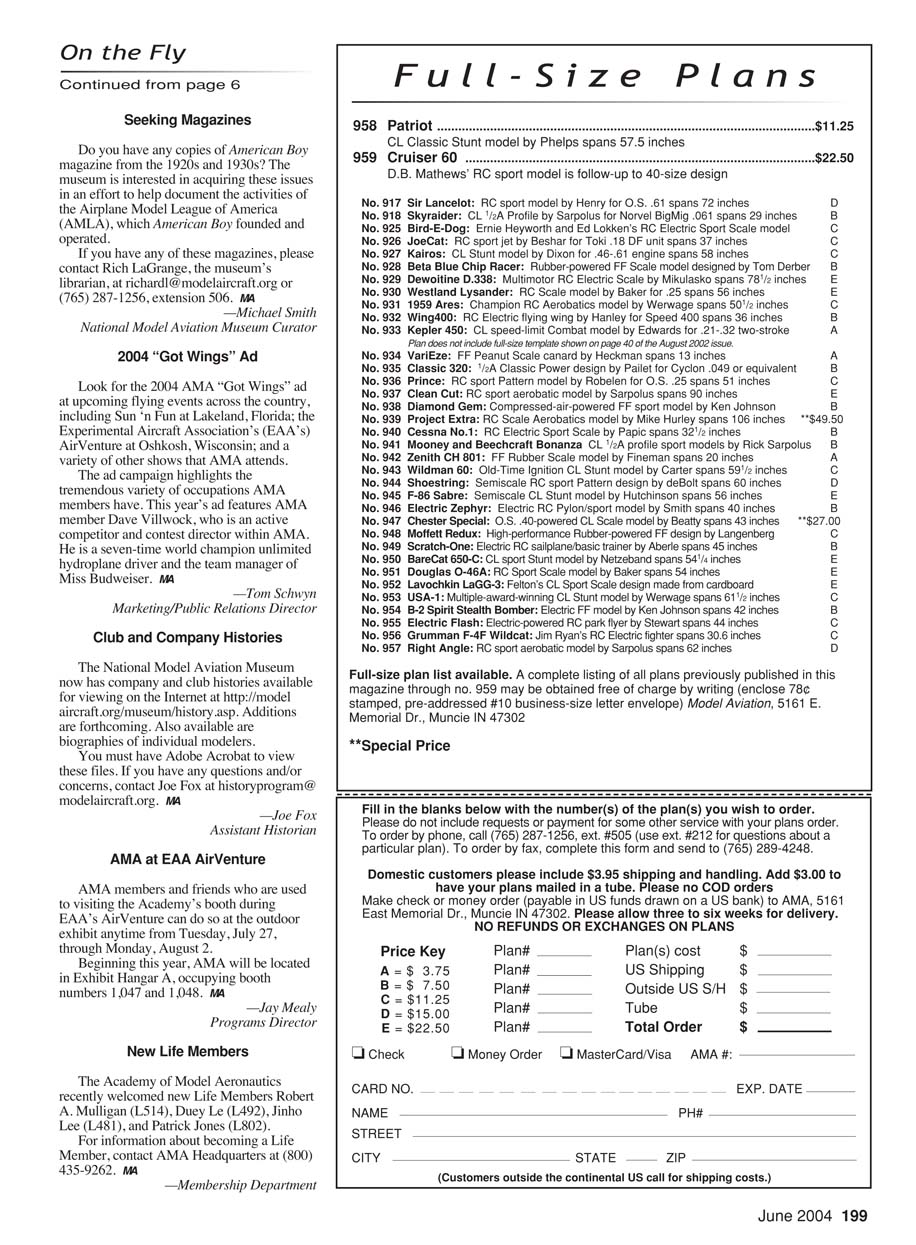
959 Cruiser 60 ........................................................ $22.50 D.B. Mathews' RC sport model is follow-up to 40-size design
Transcribed from original scans by AI. Minor OCR errors may remain.

