
Cumulus
A half-size version for 1/2A Texaco
Ken Cashion
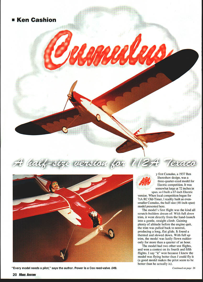
My first Cumulus, a 1937 Ben Shereshaw design, was a three-quarter-sized model for electric competition. It was somewhat large at 72 inches in span, so I built a 67-inch electric version. When local competition began for 1/2A RC Old-Timer, I readily built an even smaller Cumulus, the half-size (48-inch-span) model presented here.
The model's first flight was the kind all scratch-builders dream of: with full down trim, it went directly from the hand-launch into a gentle, straight climb. Gaining plenty of altitude before the engine quit, the trim was pulled back to neutral, producing a long, flat glide. It found a thermal and slowed down. With full up trim, the model was lazily flown rudder-only for more than a quarter of an hour.
The model had two other test flights, and won a contest on its fourth and fifth flights. I say "it" won because I knew the model was flying better than I could fly it (a good model makes the pilot seem to be better than he actually is).
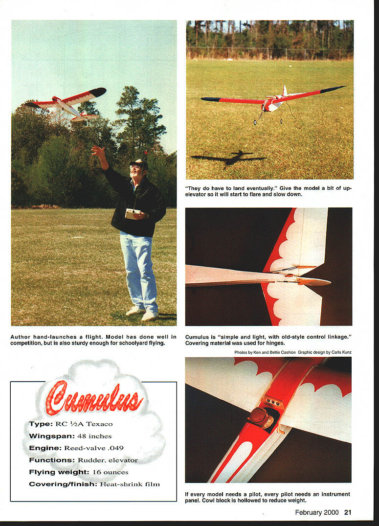
Author hand-launches a flight. Model has done well in competition, but is also sturdy enough for schoolyard flying.
"They do have to land eventually." Give the model a bit of up-elevator so it will start to flare and slow down.
Cumulus is simple and light, with old-style control linkage. Covering material was used for hinges.
If every model needs a pilot, every pilot needs an instrument panel. Cowl block is hollowed to reduce weight.
Type: RC 1/2A Texaco
- Wingspan: 48 inches
- Engine: Reed-valve .049
- Functions: Rudder, elevator
- Flying weight: 16 ounces
- Covering/finish: Heat-shrink film
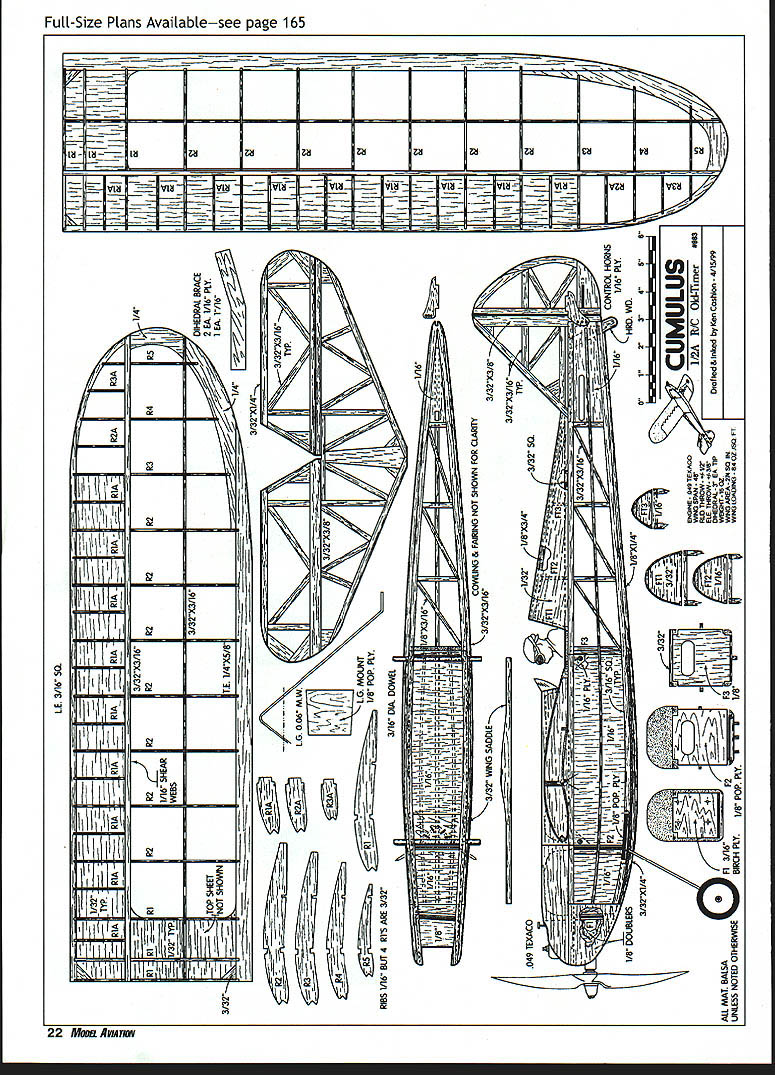
In scaling this model, I was as true to the original plans as possible, but some concessions must be made when scaling a 96-inch-span model to 48 inches. The airfoil, construction method, proportions, areas, etc., are consistent with Shereshaw's original plans; however, some minor alterations were made in the construction and trimming of the model, and these are shown on the plans.
This model is a sturdy sport flier for a schoolyard, as well as a good competition model. It is not superlight, but by the same token, it can fly in wind that might ground the superlight models. Should the builder want a much lighter model, there are many places where some judicious carving and sanding could save weight.
CONSTRUCTION
Empennage
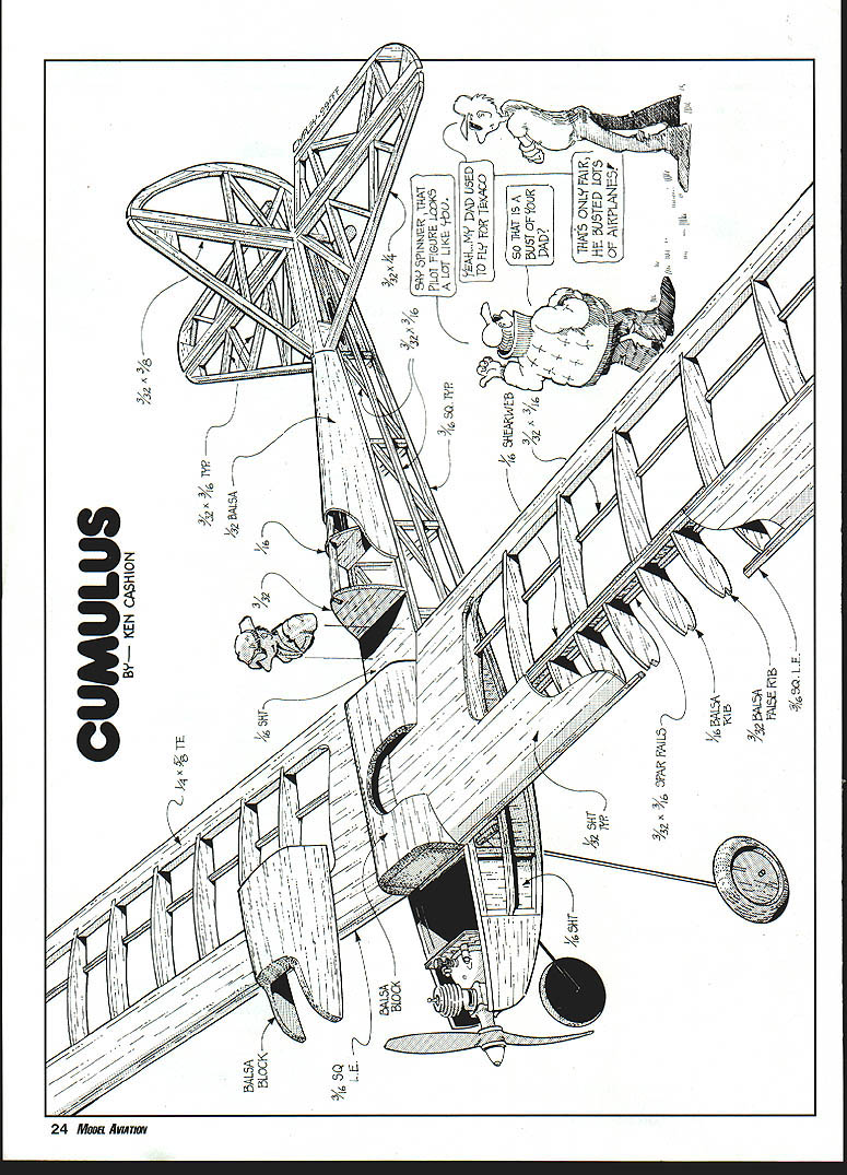
Build all empennage framework over the plans. The spars, leading edges (LE), and trailing edges (TE) are from hard stock; the rest from soft. The horizontal tail spar is built in one piece, and after final sanding, the single elevator is cut free of the stabilizer. The hingelines on the horizontal and vertical tails were beveled and hinged with covering material.
Wing
- The wing halves are built at the same time, with the wing battens butted at the root. It is recommended that the TE material be shaped and notched for ribs before it is secured to the plans. The TE will be the reference for all other wing components.
- Slip all R2s into TE notches, press the top spar into place (allow a little extra length at tips), and pin the LE in place. Trim and fit all R1As, disregarding all other ribs at this time. After confirming alignment and fit, CyA pressure-glue all joints; I used Hobbico Bullet thick and thin CyA, with their accelerator.
- Carefully remove the wing, lay the wing bottom-up on the building board, fit and CyA the bottom spars in place. Resecure the wing bottom-down on the building board.
- The remainder of the tip TE, tip, and tip LE can be cut from stock, leaving final shaping until after the wing is assembled.
- Trim and attach R3, R4, and R5, using the top spar for reference. CyA tip ribs, TE, LE, R2A, and R3A in place.
- Remove the wing from the board and rough-shape the tips to match the plans. Keep the top wing surface straight, adjusting lower spars and tips to conform to lower rib shape. This is important to maintain left/right tip symmetry and avoid washout.
- Cut dihedral braces to size. CyA a dihedral laminate of one 1/8 balsa brace with two 1/16 plywood braces and join the wings with the laminated brace between upper and lower spars. The brace should not alter the distance between the spars; use R1 for a reference.
- After confirming that the dihedral is correct (three inches under each wingtip) and the joints match, CyA the LE, TE, and dihedral braces in place. Trim and add R1s, and CyA as fit is confirmed.
- Add the bottom-center 1/32 sheeting at wing joints between spars and TE. CyA gussets at LE and TE and then add top-center sheeting from spar to TE. CyA shear webbing at the back edge of the upper and lower spar as per plan. Use a piece of wing sheeting material to confirm fit and to keep the top sheeting from lifting during sanding.
- Fit the wing fillets and fairing pieces, sanding to a smooth contour. Install any remaining tip sheeting and finish shaping the tips to plan outlines. Sand the completed wing smooth and true, ready for covering.
- Ensure that all rib-to-spar-to-LE clearances are correct, and the wing is ready for LE sheeting. CyA this 1/32 sheeting in place and final-shape sand the wing.
Fuselage
- The fuselage sides are built over the plans, with the 1/16 sheet reinforcements secured between 3/16 square longerons. Leave space for F2 (1/8 poplar plywood). This 1/16 should be flush with the outside surfaces of the longerons so it supports the side stringers. This means there is a right and left fuselage side. During construction, the 1/16 for the right side can be in contact with the building board; the 1/16 on the left side will require 1/8 shims between it and the building surface.
- Add 1/16 sheet at the rear of the fuselage to reinforce the area where the pushrods exit. The 1/8 cowl cheek doublers and oversized side stringers are added later.
- The sides are lifted from the plans and F2 and F3 are CyAed to the sides. Confirm correct alignment, trimming as necessary, then press the aft fuselage sides together and glue. CyA the remainder of the square cross-pieces to the fuselage top and bottom, keeping everything parallel and even. Add the remainder of the fuselage diagonal braces at the fuselage bottom only. Leave the top fuselage cowling and aft fairing for later.
- Cut F1 (firewall) to shape from birch plywood, drill, and press 2-56 blind nuts in rear of firewall. (Hole spacing is for the Cox reed-valve engines.)
- Temporarily mount the engine to confirm fit, then remove the engine and press the forward fuselage sides to mate F1; CyA in place. Note engine/F1 offset. If F1 is secured as shown on plans, a large or small reed-valve engine fuel tank can be used. (The small-tank engine is shown on the plans.)
- Bend the 1/16 music wire landing gear to the flat shape shown on the plans, then bend both sides at the same time where indicated by the interrupted line. Cut the LG mount (1/8 poplar plywood) to shape, mark the wire position on the mount, and drill holes to secure the landing gear wire to the LG mount. Use carpet thread, small brass wire, or similar material to secure the landing gear. Cover well with epoxy.
- Attach LG mount to the inside lower longerons and CyA in place. I used 1/2-inch-diameter wheels from my scrap box—make unknown. The wheels should be light and streamlined; they won't get much wear.
- Add the 1/8 cowl doublers, one on the outside of the fuselage, one on the inside. CyA cross-grained 1/16 sheet on the bottom from F3 to just behind F1, and 1/8 sheet from there to the nose. Glue the 1/16 plywood wing dowel reinforcement in place and drill for the 3/16 diameter dowel. Cut and attach the 3/32 wing saddle to the top sides of the fuselage.
- Attach the wing and confirm fit and alignment to fuselage, trimming the wing saddle as necessary.
- Cut the fuselage cowling block to mate the upper surface of the wings and fuselage from the nose to the forward edge of the cockpit. Carve and sand the block to the shape shown on the plans. Cut the nose cowling free from the wing cowling and hollow both to remove as much material as practical. Any interior area that might be exposed to fuel should be liberally covered with CyA and accelerator.
- Reattach the wing, check wing/cowl/fuselage alignment, then glue the wing cowling to the wing. Use a light filler such as Balsa Magic where necessary for smooth, flowing lines.
Assembly
- Add the Popsicle®-stick tailskid. Align the fin and stab on the fuselage by trimming the fuselage for fit, then add the 1/16 stabilizer mount between the longerons.
- The empennage can be added now and covered with the fuselage, or it can be covered and attached as a unit to a covered fuselage; I prefer the latter.
- When empennage alignment and fit are confirmed, mark mating surface edges with a pencil so these areas can be left free of covering material. This will strengthen the joint when the empennage is attached as a covered unit.
- Cut FT1, FT2, and FT3 to shape and add the 3/32 cockpit floor. CyA FT1 at the aft edge of the cockpit floor. Note: 3/32 square is used at the edge of all aft, top cowling to provide a bonding surface for the 1/32 covering as it is wrapped over formers.
- CyA FT2 and FT3 to the fuselage. The capstrip should be CyAed to the top of the formers at the same time. Trim and sand the capstrip to conform to the cowling shape. When you are satisfied of good fit, CyA 1/32 over the formers. Add oversized side and bottom stringers so they can be shaped on the model, using the plans for reference.
- Shape and sand all from nose to tail to generate fair lines and pleasing shape. The battery/nose hatch can be secured in your preferred manner.
- Shape 1/16 plywood control horns, drill for pushrod wire, cover with CyA, and when the glue has fully set, redrill. CyA horns to rudder and elevator, and using masking tape as temporary hinges, measure for pushrod lengths. Make the ends of the pushrods/clevises to mate with control horns, but leave the other ends oversized and unfinished; they will be completed after the servos are installed.
- Cover the model with your preferred material, then align and CyA the empennage in place.
Equipment Installation
- Servos may be mounted any number of ways, but try to get the center of their weight nearly four inches aft of F2. I used microservos, but I found long-term reliability better with standard-size servos in this area.
- The rudder and elevator servos should be mounted on a plywood plate that is screwed to the fuselage sides. Install the pushrods and adjust the control throws as shown on the plans. Check all linkages and secure clevises with soldered eyes or thread-locking glue.
- Battery and receiver should be located to obtain the correct center of gravity (CG). Balance the model at the CG location shown on the plans with the covering and all equipment installed. Adjust battery location as needed to attain the specified CG.
Final Assembly
- Install the cowl, spinner, and propeller. Make final check of control surface throws, surface centering, and servo reversals.
- Ensure all glue joints are fully cured and any gaps are filled and sanded smooth. Clean the model of any dust and give it a final inspection before test flying.
FLYING
- Conduct range checks and motor runs before taking off. Use a large, smooth flying field, and perform the initial flights in calm conditions.
- Trim the control surfaces for straight flight, then check turns, stalls, and slow flight characteristics. Make small adjustments to down and right thrust as necessary for coordinated flight.
- With careful building and setup, the Cumulus will reward you with stable, predictable sport-flying characteristics and gentle stall behavior—ideal for relaxed flying sessions and precision landing practice.
- There is sufficient space for the battery to be shifted to adjust for the CG change when switching between short and long fuel tanks. None of my models required additional weight to balance.
If the Cumulus is built true, has proper CG placement and control-surface movement, the model will fly with little input from the pilot.
For sport flying, a Golden Bee, Black Widow, or Texaco engine would be fine; however, local competition rules permit the use of either tank on any reed-valve .049 engine, and there are many variables for competition.
If the target flight time is 10 minutes and two models of similar wing loading reach the same altitude before their engines quit, one might assume this to be comparable flying; however, if one engine ran four-plus minutes to get to that altitude and the other engine ran only three minutes, one model has accumulated at least 60 more flight seconds than the other—before they start looking for lift in the same air.
So the question becomes: How long can I make the engine run so that when it runs out of fuel, it is as high as I can comfortably fly the model?
Simple question; many answers.
There is no point in going to a contest and spending the day changing fuel and props, adjusting needle valves, changing head gaskets, and the like. This should be done at home so when at the contest, it is already known that the best tradeoffs will be between the current weather, expected engine performance, and ease of engine starting and adjustment.
On cool, still mornings with a well-broken-in Texaco engine, I might use 20% nitro fuel (to aid starting), two head gaskets, and a 7 x 8 APC prop. This will result in a moderately easy engine to start and adjust, and a 6,000 rpm four-minute-plus engine run on the large tank. It will have enough zing to get way, way up there before the engine quits.
As the day heats up, I drop back to a 7 x 7 prop. As the wind increases, I might end up with a 7 x 5 or 7 x 4 prop. The rpm may be up to 8,200. Because of the wind, more thrust is needed—at a cost of engine run time, but not necessarily with a reduction of altitude.
A Texaco engine with one head gasket and a 7 x 5 prop would provide good service for sport flying with easy starting and long, slow flights even in a moderate wind. I know we generally expect to hear .049s scream, but for this kind of flying, a sloppy, sputtering 7,500 rpm will work to our advantage.
Ken Cashion 157 Tennyson Cove Picayune MS 39466 [email protected]
Transcribed from original scans by AI. Minor OCR errors may remain.

