
Curtiss-Wright CW-1 Junior
By Ernie Heyworth
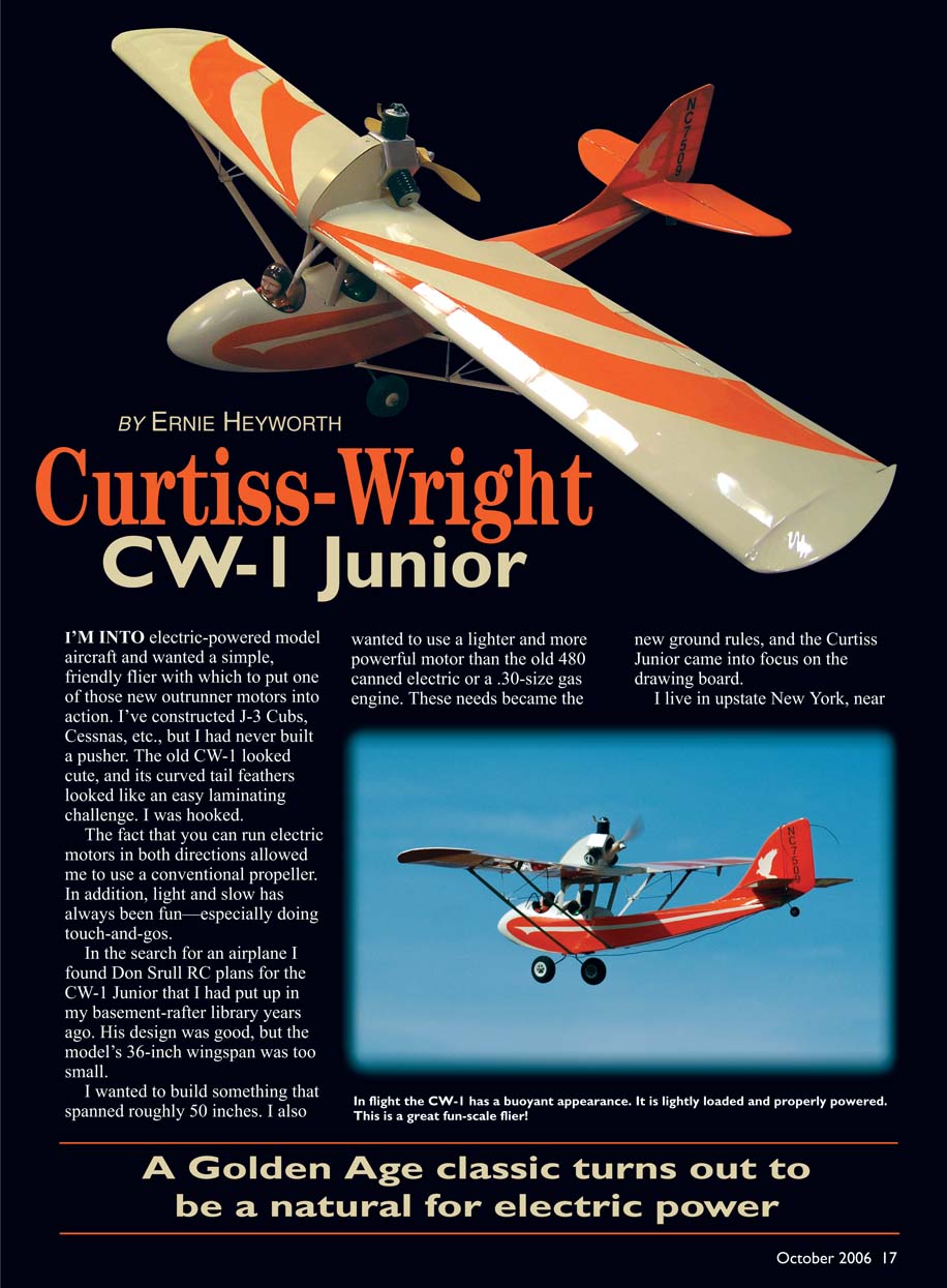
I'm into electric-powered model aircraft and wanted a simple, friendly flier with which to put one of those new outrunner motors into action. I've constructed J-3 Cubs, Cessnas, etc., but I had never built a pusher. The old CW-1 looked cute, and its curved tail feathers looked like an easy laminating challenge. I was hooked.
The fact that you can run electric motors in both directions allowed me to use a conventional propeller. In addition, light and slow has always been fun—especially doing touch-and-gos.
In the search for an airplane I found Don Srull RC plans for the CW-1 Junior that I had put up in my basement-rafter library years ago. His design was good, but the model's 36-inch wingspan was too small.
I wanted to build something that spanned roughly 50 inches. I also wanted to use a lighter and more powerful motor than the old 480 canned electric or a .30-size gas engine. These needs became the new ground rules, and the Curtiss Junior came into focus on the drawing board.
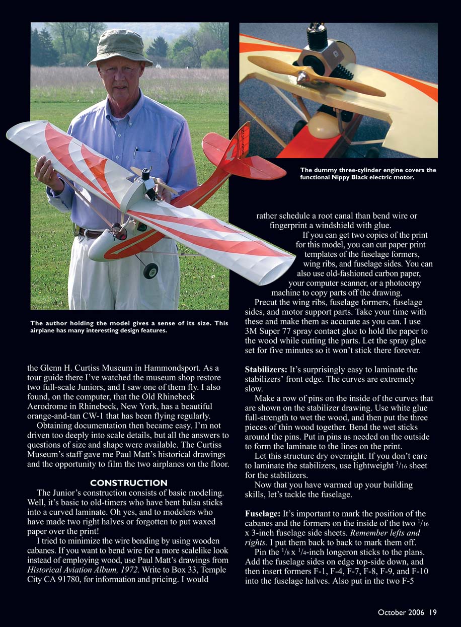
I live in upstate New York, near the Glenn H. Curtiss Museum in Hammondsport. As a tour guide there I’ve watched the museum shop restore two full-scale Juniors, and I saw one of them fly. I also found, on the computer, that the Old Rhinebeck Aerodrome in Rhinebeck, New York, has a beautiful orange-and-tan CW-1 that has been flying regularly.
Obtaining documentation then became easy. I’m not driven too deeply into scale details, but all the answers to questions of size and shape were available. The Curtiss Museum’s staff gave me Paul Matt’s historical drawings and the opportunity to film the two airplanes on the floor.
A Golden Age classic turns out to be a natural for electric power
Curtiss-Wright CW-1: A Brief History
This airplane was developed during 1929 and the early 1930s, during the Great Depression; luxury airplanes weren't selling then. At the Buffalo, New York, plant design center, Glenn Curtiss and Walter Beech (of the later Beech Aircraft Corporation) decided to build a light, inexpensive airplane. It was to be constructed at the Saint Louis, Missouri, plant, which needed work or faced shutdown.
Curtiss and Beech wanted an airplane that would weigh less than 1,000 pounds and hoped to sell it for roughly $1,500. Today's ultralights weigh approximately 300 pounds and have 50-horsepower engines. They cruise at 70 mph and cost roughly $8,000. The ultralights and the Junior are almost the same size.
The CW-1's design came from the English Buzzard and the wood Curtiss-Robertson Skeeter. Glenn never outgrew his love for the pusher-type aircraft. His first designs were pushers that were similar to the Wright brothers' Wright Flyer.
Glenn's June Bug and other aircraft he developed were advancements beyond the Wright Flyer. His team made design changes to the early June Bug such as adding wheels, pontoons, ailerons, bigger engines, and better controls. He established the aeronautical leading edge of the time.
The Wrights and Curtiss locked each other up in court battles over the invention of all airplanes and all motor flying machines. This patent fight set the US back in the design progress of airplanes at the outbreak of World War I. The Europeans took the leading-edge development. They added tractor engines, better wing structures, and much greater performance to the basic airplane.
The US government finally paid off Glenn and Orville to settle their dispute so that the Americans could catch up with the Europeans. Curtiss and the Wrights then collaborated to make radial engines and some of the greatest airplanes of World War II.
The CW-1 Junior was a bit of a joke among the pilots of the day. It looked a little like the Aeronca C-3 "Flying Bathtub" or a cross between a seaplane and a sailplane, but it sold well during hard times.
The Junior was easy to fly, it had a low stall speed, it could land in small farm fields, it had a metal frame, and it had good visibility for photo surveying. Air-show pilots loved this airplane; the large wing let them park it into the wind.
The CW-1 was a money-maker for giving rides, although a few passengers walked into the pusher propeller. The barnstormers used it to do the flying farmer routine. Most of them put more powerful engines on them. The Szekely wasn't dependable; it threw oil and often blew a jug into the pusher propeller.
The Curtiss-Wright Junior certainly has left its mark on aviation history, and it is worth modeling.
—Ernie Heyworth
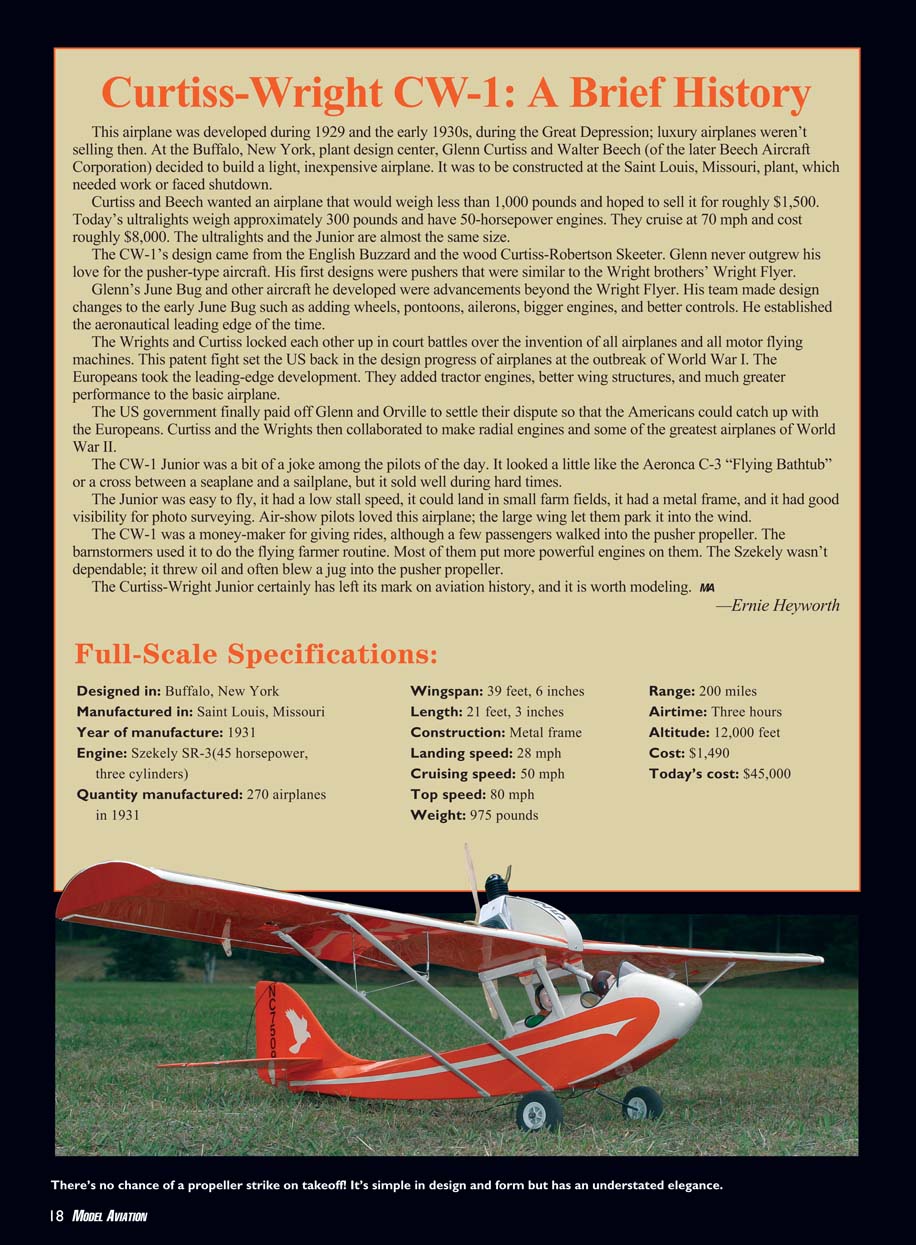
Full-Scale Specifications
- Designed in: Buffalo, New York
- Manufactured in: Saint Louis, Missouri
- Year of manufacture: 1931
- Engine: Szekely SR-3 (45 horsepower, three cylinders)
- Quantity manufactured: 270 airplanes in 1931
- Wingspan: 39 ft 6 in
- Length: 21 ft 3 in
- Construction: Metal frame
- Landing speed: 28 mph
- Cruising speed: 50 mph
- Top speed: 80 mph
- Weight: 975 pounds
- Range: 200 miles
- Airtime: 3 hours
- Altitude: 12,000 feet
- Cost (1931): $1,490
- Today's cost (approx.): $45,000
Construction
The Junior’s construction consists of basic modeling skills. Well, it’s basic to old-timers who have bent balsa sticks into a curved laminate. Oh yes, and to modelers who have made two right halves or forgotten to put waxed paper over the print!
I tried to minimize the wire bending by using wooden cabanes. If you want to bend wire for a more scale-like look instead of employing wood, use Paul Matt’s drawings from Historical Aviation Album (1972). Write to Box 33, Temple City CA 91780, for information and pricing. I would rather schedule a root canal than bend wire or fingerprint a windshield with glue.
If you can get two copies of the print for this model, you can cut paper print templates of the fuselage formers, wing ribs, and fuselage sides. You can also use old-fashioned carbon paper, your computer scanner, or a photocopy machine to copy parts off the drawing. Precut the wing ribs, fuselage formers, fuselage sides, and motor support parts. Take your time with these and make them as accurate as you can. I use 3M Super 77 spray contact glue to hold the paper to the wood while cutting the parts. Let the spray glue set for five minutes so it won’t stick there forever.
Stabilizers
It’s surprisingly easy to laminate the stabilizers’ front edge. The curves are extremely gentle.
Make a row of pins on the inside of the curves that are shown on the stabilizer drawing. Use white glue full-strength to wet the wood, and then put the three pieces of thin wood together. Bend the wet sticks around the pins. Put in pins as needed on the outside to form the laminate to the lines on the print.
Let this structure dry overnight. If you don’t care to laminate the stabilizers, use lightweight 3/16" sheet for the stabilizers.
Fuselage
It’s important to mark the position of the cabanes and the formers on the inside of the two 1/16" x 3" fuselage side sheets. Remember lefts and rights. I put them back to back to mark them off.
Pin the 1/8" x 1/4" longeron sticks to the plans. Add the fuselage sides on edge, top-side down, and then insert formers F-1, F-4, F-7, F-8, F-9, and F-10 into the fuselage halves. Also put in the two F-5 formers with enough of a gap to allow your landing-gear wire to slide between them.
Let the structure dry, unpin it, take it off the board, turn it over, and put the two 1/8" x 1/4" longerons on the curved bottom of the fuselage. Start thinking about getting the cabanes glued onto the lines inside the fuselage sides.
Getting the cabanes in correctly worried me the most. Remember that the final alignment is when you drill the holes in the wing plywood ribs to join the wing to the fuselage.
Find the drawing template that will be used between the wing and the fuselage. Transfer the template to two stiff pieces of corrugated cardboard. Pin them onto the fuselage. Notch the longerons for the cabanes to slide through.
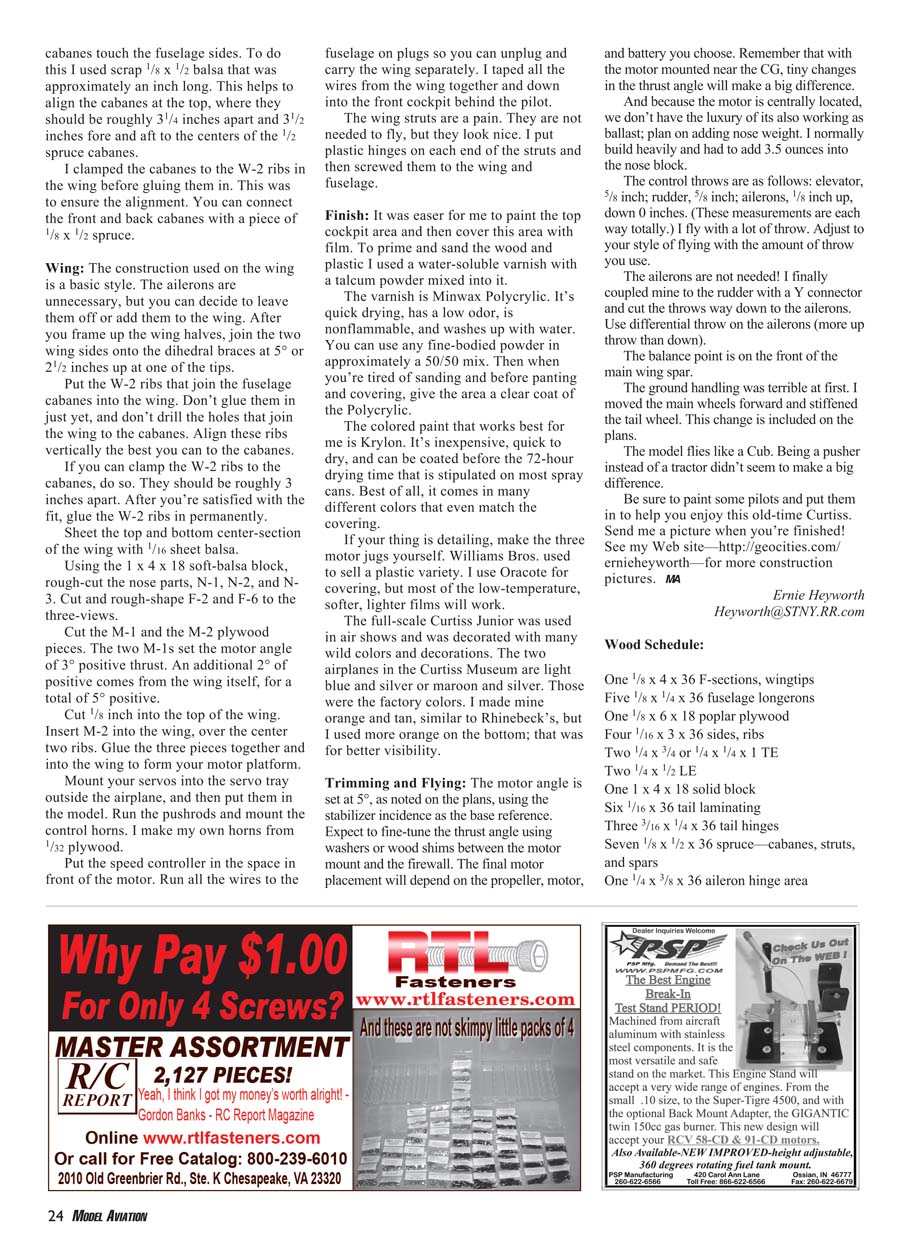
You will have to shim inside the fuselage where the cabanes touch the fuselage sides. To do this I used scrap 1/8" x 1/2" balsa approximately an inch long. This helps to align the cabanes at the top, where they should be roughly 3 1/4" apart and 3 1/2" fore and aft to the centers of the 1/2" spruce cabanes.
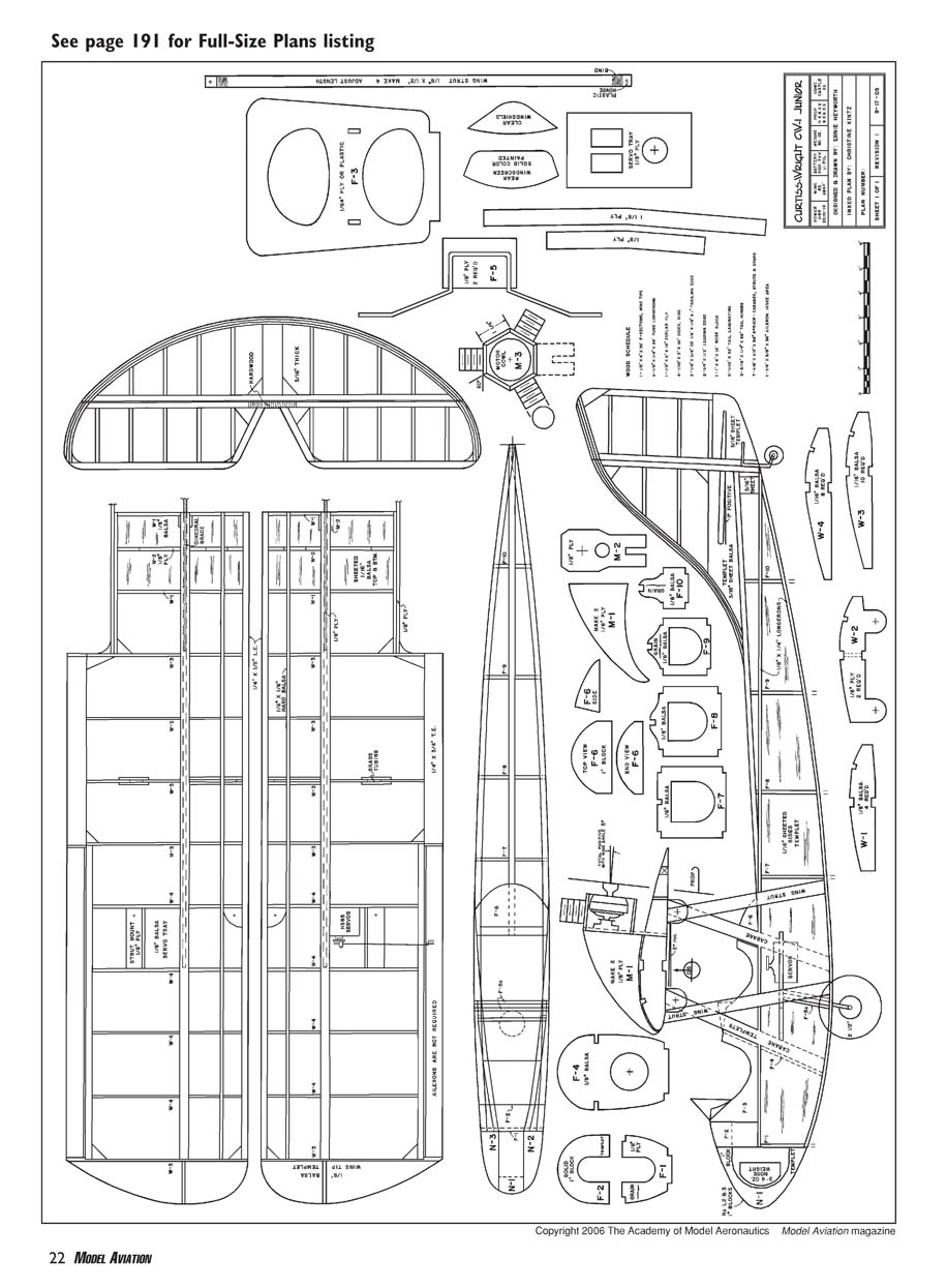
I clamped the cabanes to the W-2 ribs in the wing before gluing them in. This was to ensure the alignment. You can connect the front and back cabanes with a piece of 1/8" x 1/2" spruce.
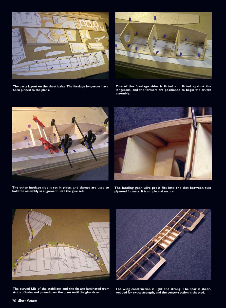
One fuselage side is fitted and aligned against the longerons, and the formers are positioned to begin the crutch assembly. The other fuselage side is set in place, and clamps are used to hold the assembly in alignment until the glue sets.
The landing-gear wire press-fits into the slot between two plywood formers. It is simple and secure!
The curved leading edges of the stabilizer and the fin are laminated from strips of balsa and pinned over the plans until the glue dries.
Wing
The wing construction is light and strong. The spar is shear-webbed for extra strength, and the center-section is sheeted.
The construction used on the wing is a basic style. The ailerons are unnecessary, but you can decide to leave them off or add them to the wing. After you frame up the wing halves, join the two wing sides onto the dihedral braces at 5° (about 2 1/2" up at the tip).
Put the W-2 ribs that join the fuselage cabanes into the wing. Don't glue them in just yet, and don't drill the holes that join the wing to the cabanes. Align these ribs vertically the best you can to the cabanes.
If you can clamp the W-2 ribs to the cabanes, do so. They should be roughly 3" apart. After you're satisfied with the fit, glue the W-2 ribs in permanently.
Sheet the top and bottom center-section of the wing with 1/16" balsa sheet.
Using the 1" x 4" x 18" soft-balsa block, rough-cut the nose parts N-1, N-2, and N-3. Cut and rough-shape F-2 and F-6 to the three-views.
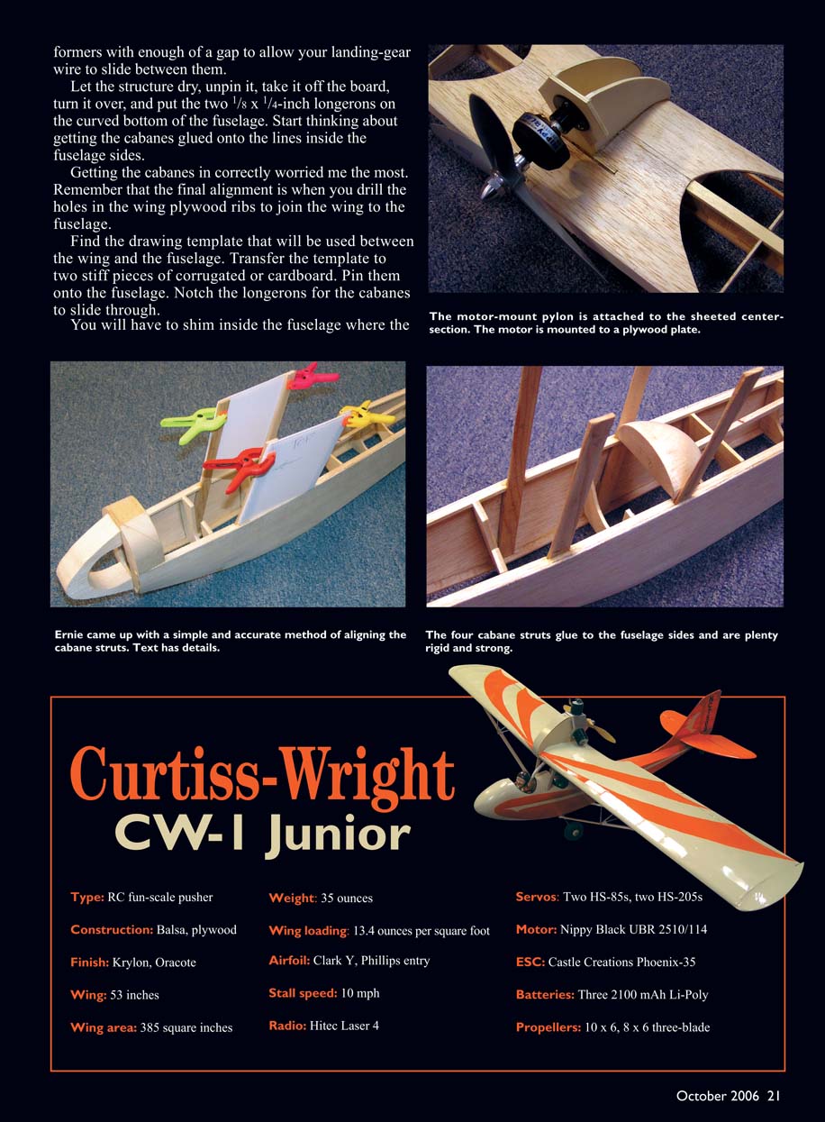
Cut the M-1 and the M-2 plywood pieces. The two M-1s set the motor angle at 3° positive thrust. An additional 2° of positive comes from the wing itself, for a total of 5° positive.
Cut 1/8" into the top of the wing. Insert M-2 into the wing, over the center two ribs. Glue the three pieces together and into the wing to form your motor platform.
Mount your servos into the servo tray outside the airplane, and then put them in the model. Run the pushrods and mount the control horns. I make my own horns from 1/32" plywood.
Put the speed controller in the space in front of the motor. Run all the wires to the fuselage on plugs so you can unplug and carry the wing separately. I taped all the wires from the wing together and down into the front cockpit behind the pilot.
The wing struts are a pain. They are not needed to fly, but they look nice. I put plastic hinges on each end of the struts and then screwed them to the wing and fuselage.
Finish
It was easier for me to paint the top cockpit area and then cover this area with film. To prime and sand the wood and plastic I used a water-soluble varnish with talcum powder mixed into it.
The varnish is Minwax Polycrylic. It's quick drying, has a low odor, is nonflammable, and washes up with water. You can use any fine-bodied powder in approximately a 50/50 mix. Then when you're tired of sanding and before painting and covering, give the area a clear coat of the Polycrylic.
The colored paint that works best for me is Krylon. It's inexpensive, quick to dry, and can be coated before the 72-hour drying time that is stipulated on most spray cans. Best of all, it comes in many different colors that even match the covering.
If your thing is detailing, make the three motor jugs yourself. Williams Bros. used to sell a plastic variety. I use Oracote for covering, but most of the low-temperature, softer, lighter films will work.
The full-scale Curtiss Junior was used in air shows and decorated with many wild colors and decorations. The two airplanes in the Curtiss Museum are light blue and silver or maroon and silver. Those were the factory colors. I made mine orange and tan, similar to Rhinebeck's, but I used more orange on the bottom; that was for better visibility.
Trimming and Flying
The motor angle is set at 5°, as noted on the plans, using the stabilizer incidence as the base reference. Expect to fine-tune the thrust angle using washers or wood shims between the motor mount and the firewall. The final motor placement will depend on the propeller, motor, and battery you choose. Remember that with the motor mounted near the CG, tiny changes in the thrust angle will make a big difference.
Because the motor is centrally located, we don't have the luxury of its also working as ballast; plan on adding nose weight. I normally build heavily and had to add 3.5 ounces into the nose block.
Recommended control throws (total each way):
- Elevator: 5/8"
- Rudder: 5/8"
- Ailerons: 1/8" up, 0" down (aileron travel may be reduced or coupled to rudder)
I fly with relatively large throws. Adjust to your style of flying with the amount of throw you use.
Use differential throw on the ailerons (more up throw than down) if you fit them. The balance point is on the front of the main wing spar.
Ground handling was poor at first. I moved the main wheels forward and stiffened the tail wheel. This change is included on the plans.
The model flies like a Cub. Being a pusher instead of a tractor didn't seem to make a big difference.
Be sure to paint some pilots and put them in to help you enjoy this old-time Curtiss. Send me a picture when you're finished! See my web site (http://geocities.com/ernieheyworth) for more construction pictures.
Ernie Heyworth [email protected]
Model Specifications (RC fun-scale)
- Type: RC fun-scale pusher
- Construction: Balsa, plywood
- Finish: Krylon, Oracote
- Wing span: 53 inches
- Wing area: 385 square inches
- Weight: 35 ounces
- Wing loading: 13.4 ounces per square foot
- Airfoil: Clark Y, Phillips entry
- Stall speed: 10 mph
- Radio: Hitec Laser 4
- Servos: Two HS-85s, two HS-205s
- Motor: Nippy Black UBR 2510/114
- ESC: Castle Creations Phoenix-35
- Batteries: Three 2100 mAh Li-Poly
- Propellers: 10x6, 8x6 three-blade
Wood Schedule
- One 1/8" x 4" x 36" — F-sections, wingtips
- Five 1/8" x 1/4" x 36" — fuselage longerons
- One 1/8" x 6" x 18" — poplar plywood
- Four 1/16" x 3" x 36" — sides, ribs
- Two 1/4" x 3/8" or 1/4" x 1/4" x 1" — TE (as required)
- Two 1/4" x 1/2" — leading edges
- One 1" x 4" x 18" — solid block (nose)
- Six 1/16" x 36" — tail laminating strips
- Three 3/16" x 1/4" x 36" — tail hinges
- Seven 1/8" x 1/2" x 36" — spruce (cabanes, struts, and spars)
- One 1/4" x 3/8" x 36" — aileron hinge area
(Use the plans as the definitive guide for exact sizes and quantities.)
Transcribed from original scans by AI. Minor OCR errors may remain.

