
De Havilland Tiger Moth
by Pat Tritle
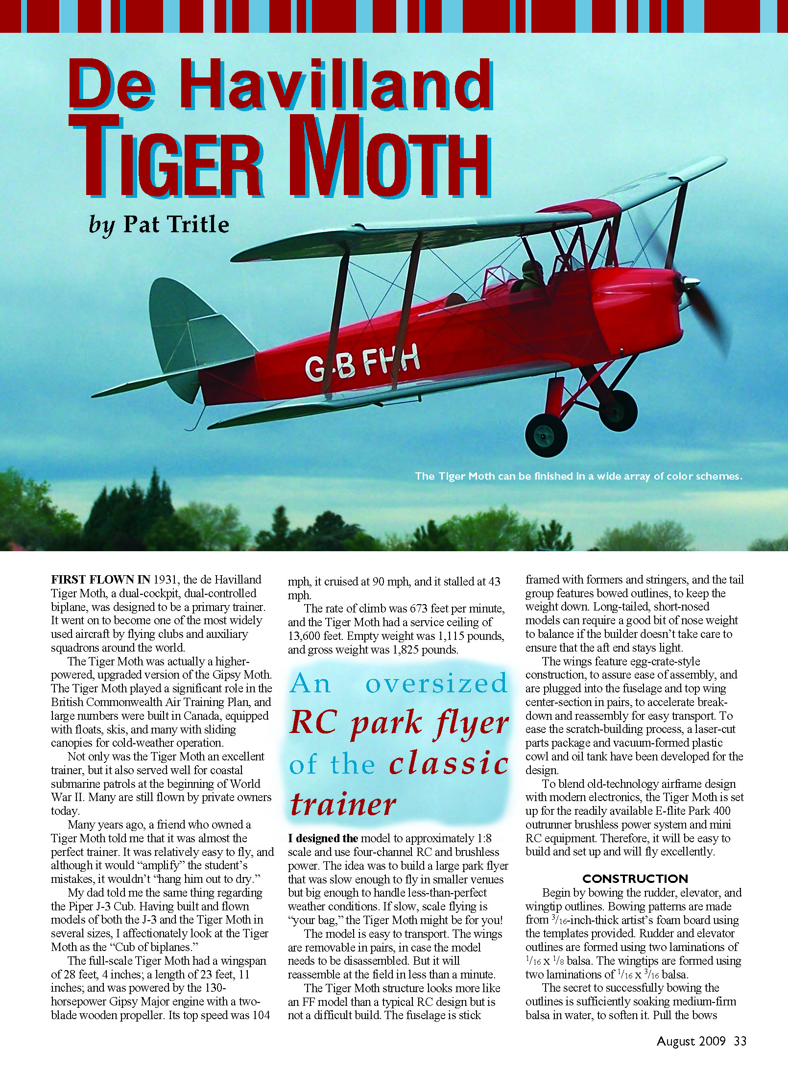
First flown in 1931, the de Havilland Tiger Moth is a dual-cockpit, dual-controlled biplane designed as a primary trainer. It became one of the most widely used aircraft by flying clubs and auxiliary squadrons around the world.
The Tiger Moth was a higher-powered, upgraded version of the Gipsy Moth. It played a significant role in the British Commonwealth Air Training Plan; large numbers were built in Canada, many equipped with floats, skis, and sliding canopies for cold-weather operation. Early in World War II the Tiger Moth also served in coastal submarine patrols. Many are still flown by private owners today.
Pilots and modelers often praise the Tiger Moth as an excellent trainer: relatively easy to fly but one that "amplifies" a student's mistakes without "hanging him out to dry." Having built and flown models of both the Piper J-3 Cub and the Tiger Moth, I affectionately consider the Tiger Moth the "Cub of biplanes."
Full-scale specifications:
- Wingspan: 28 ft 4 in
- Length: 23 ft 11 in
- Engine: 130 hp Gipsy Major with two-blade wooden propeller
- Top speed: 104 mph; cruise: 90 mph; stall: 43 mph
- Rate of climb: 673 ft/min
- Service ceiling: 13,600 ft
- Empty weight: 1,115 lb; gross weight: 1,825 lb
An oversized RC park flyer of the classic trainer
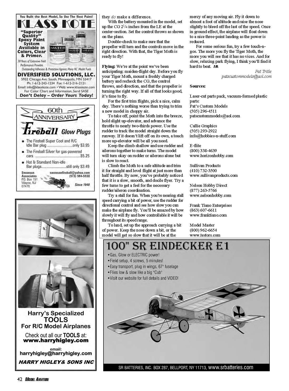
I designed an approximately 1:8-scale model using four-channel RC and brushless power. The goal was a large park flyer that’s slow enough for small venues yet big and stable enough for less-than-perfect weather. The model breaks down for transport (wings removable in pairs) and will reassemble in less than a minute at the field.
The structure resembles free-flight (FF) construction more than a typical RC design but is not difficult to build. The fuselage is stick-framed with formers and stringers; the tail uses bowed outlines to keep weight down. Long-tailed, short-nosed models can require careful weight control at the aft end to avoid excessive nose weight.
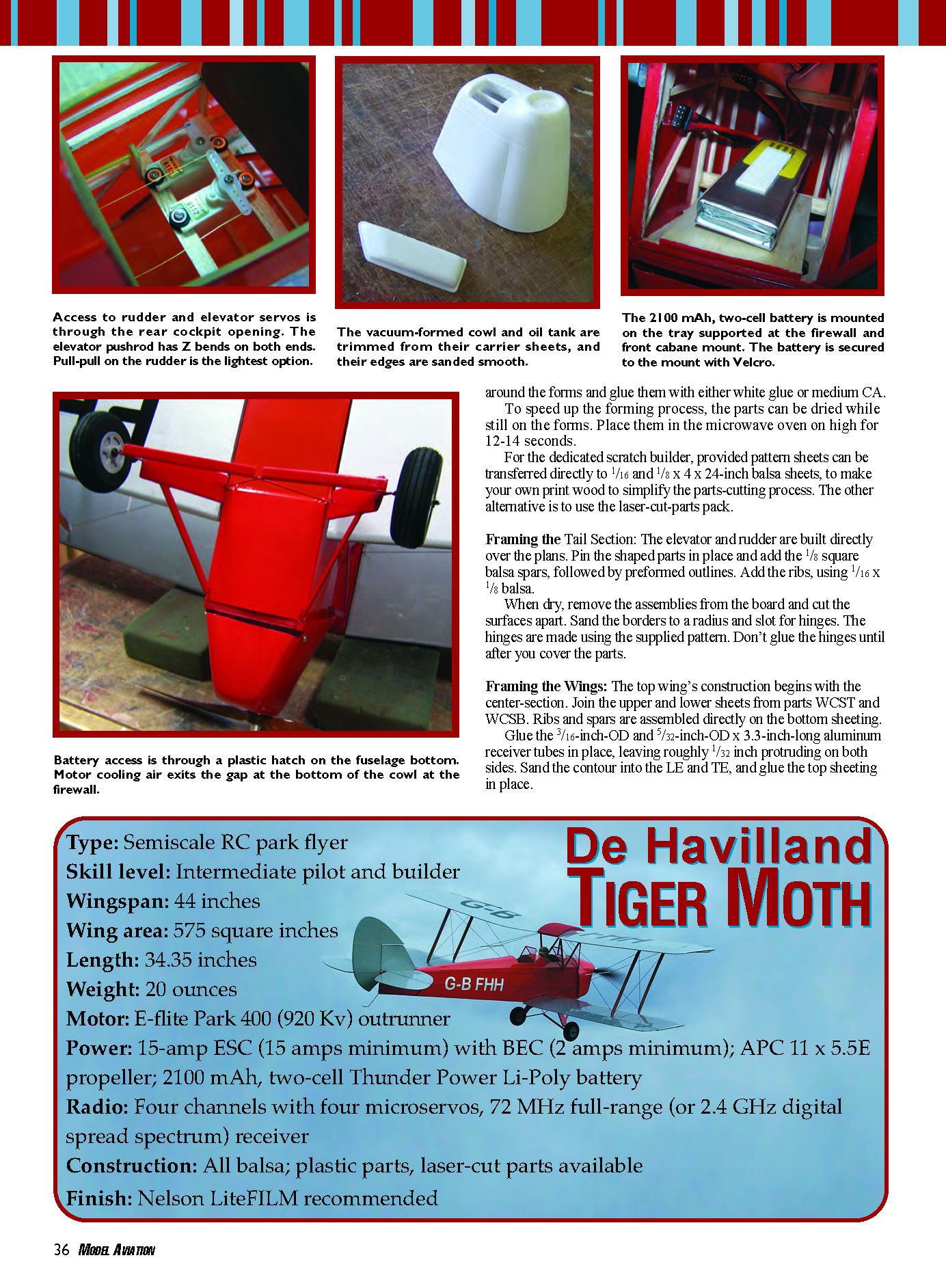
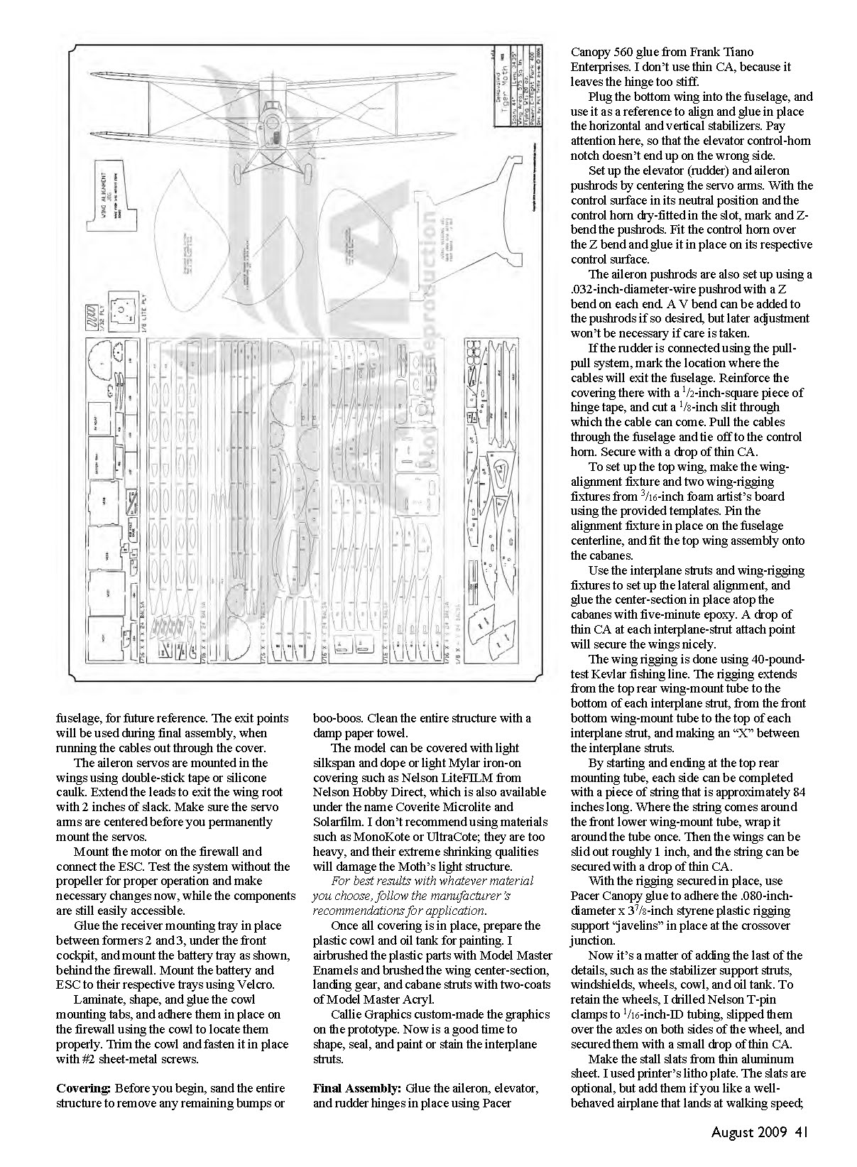
Wings use an egg-crate-style construction for ease of assembly and plug into the fuselage and top-wing center-section in pairs for quick breakdown. A laser-cut parts package and vacuum-formed plastic cowl and oil tank are available to ease scratch-building. The model is set up for the E-flite Park 400 outrunner system and mini RC equipment, making it straightforward to build, set up, and fly.
Model specifications:
- Type: Semiscale RC park flyer
- Skill level: Intermediate pilot and builder
- Wingspan: 44 in
- Wing area: 575 sq in
- Length: 34.35 in
- Weight: 20 oz
- Motor: E-flite Park 400 (920 Kv) outrunner
- Power: 15 A ESC (15 A minimum) with BEC (2 A minimum); APC 11 x 5.5E prop; 2100 mAh 2S LiPo
- Radio: Four channels with four microservos; 72 MHz full-range or 2.4 GHz DSM
- Construction: All balsa; plastic parts; laser-cut parts available
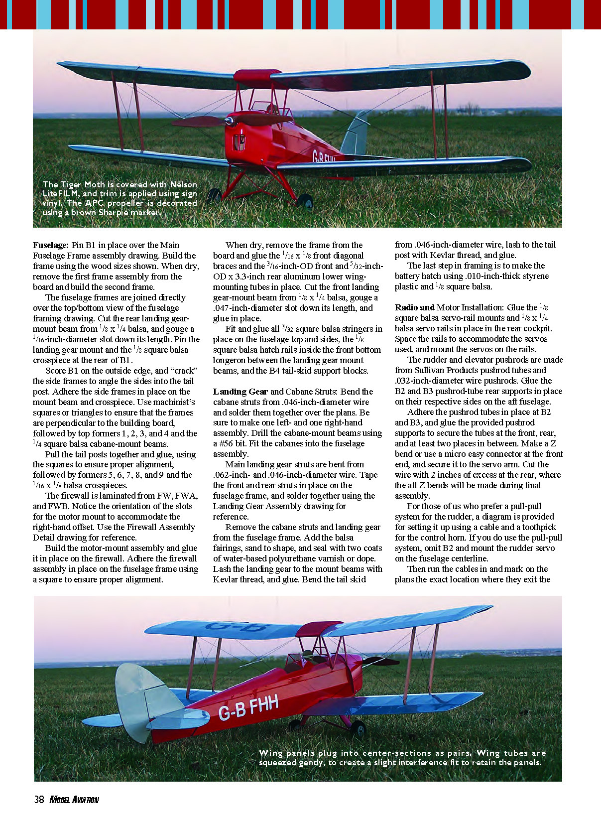
- Finish: Nelson LiteFILM recommended
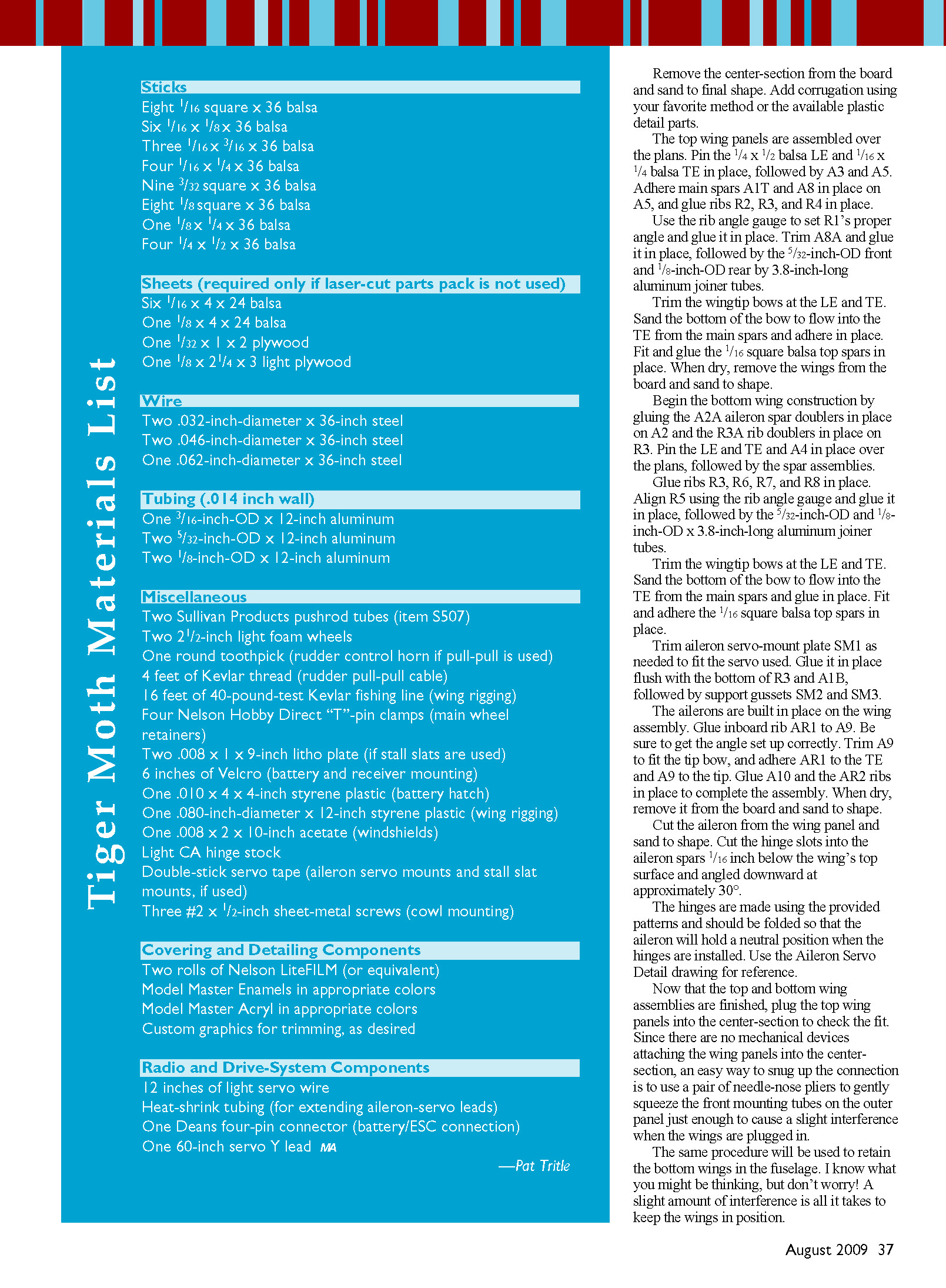
Construction
Begin by bowing the rudder, elevator, and wingtip outlines. Bowing patterns are made from 3/16-inch-thick artist’s foam board. Lay the bowed outlines around the forms and glue them with either white glue or medium CA. To speed drying, leave the parts on the forms and place them in the microwave on high for 12–14 seconds.
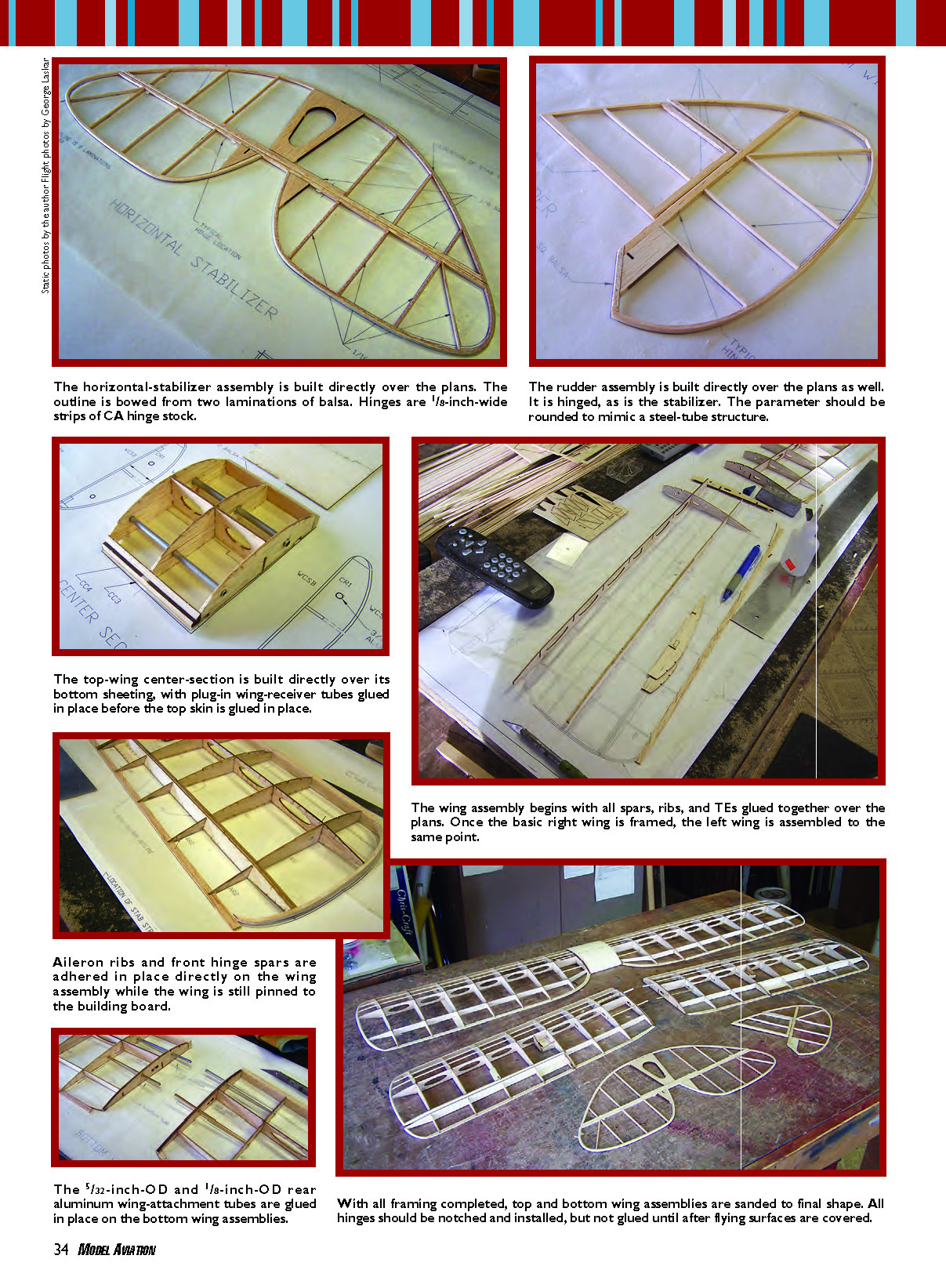
The horizontal stabilizer, rudder, and other tail parts are built directly over the plans. Outlines are bowed from two laminations of balsa. Use 1/8-inch-wide strips of CA hinge stock for hinges. Round the stabilizer perimeter to mimic a steel-tube structure. Do not glue hinges until after covering.
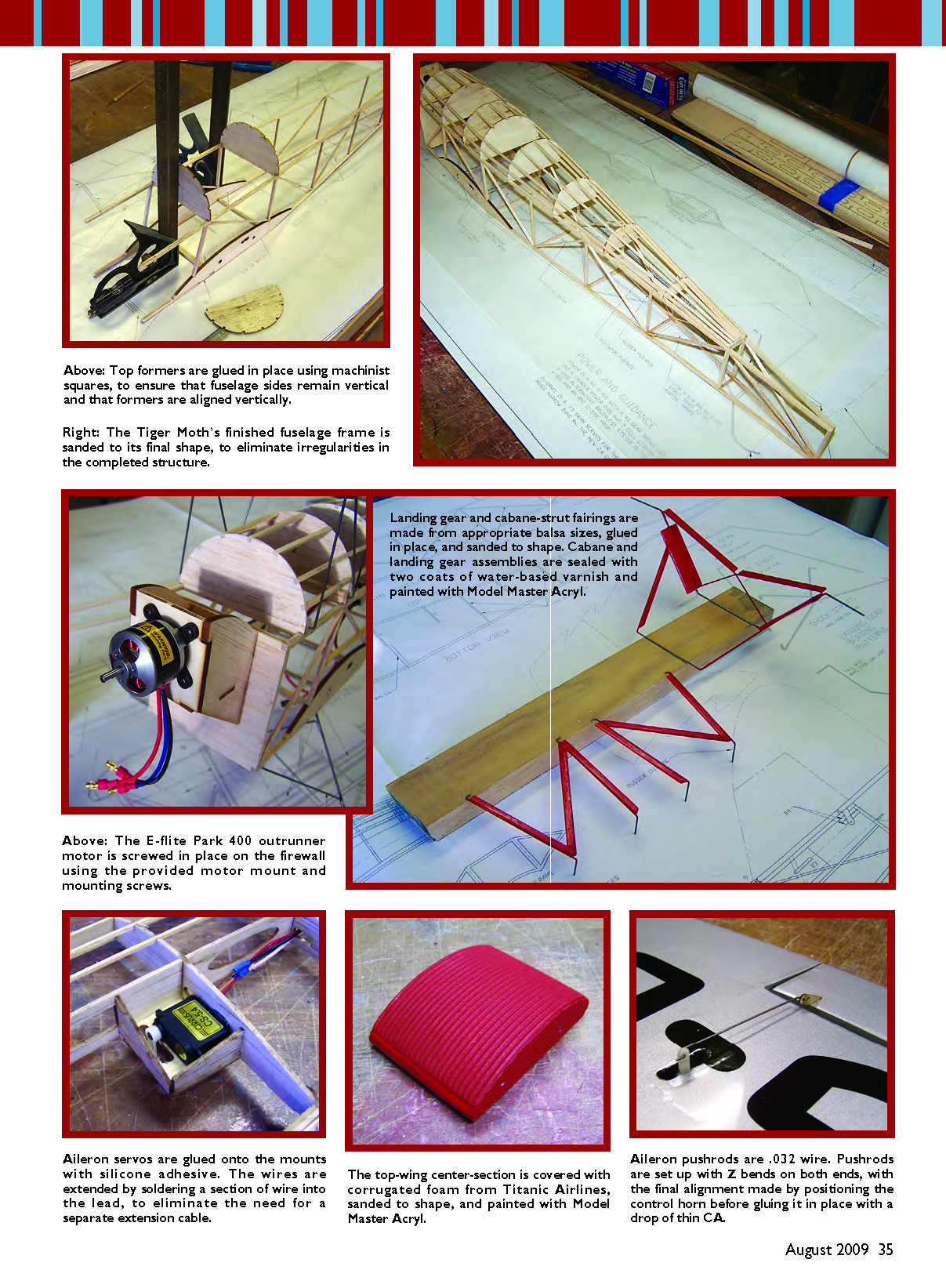
Top formers should be glued in place using machinist squares to ensure fuselage sides remain vertical and formers are vertically aligned. When the fuselage frame is sanded to final shape, remove irregularities before fairings and coverings are applied.
Aileron servos are glued onto mounts with silicone adhesive; extend servo leads by soldering a section of wire into the lead to avoid separate extension cables. Aileron pushrods are .032-inch wire with Z bends on both ends; final alignment is set by positioning the control horn before gluing it in place with a drop of thin CA.
Framing the Tail Section
- Build the elevator and rudder directly over the plans. Pin shaped parts in place, add 1/8" square balsa spars, followed by preformed outlines and ribs (1/16 x 1/8 balsa).
- When dry, remove assemblies from the board and cut the surfaces apart. Sand the borders to a radius and slot for hinges using the supplied hinge pattern.
- Do not glue the hinges until after covering.
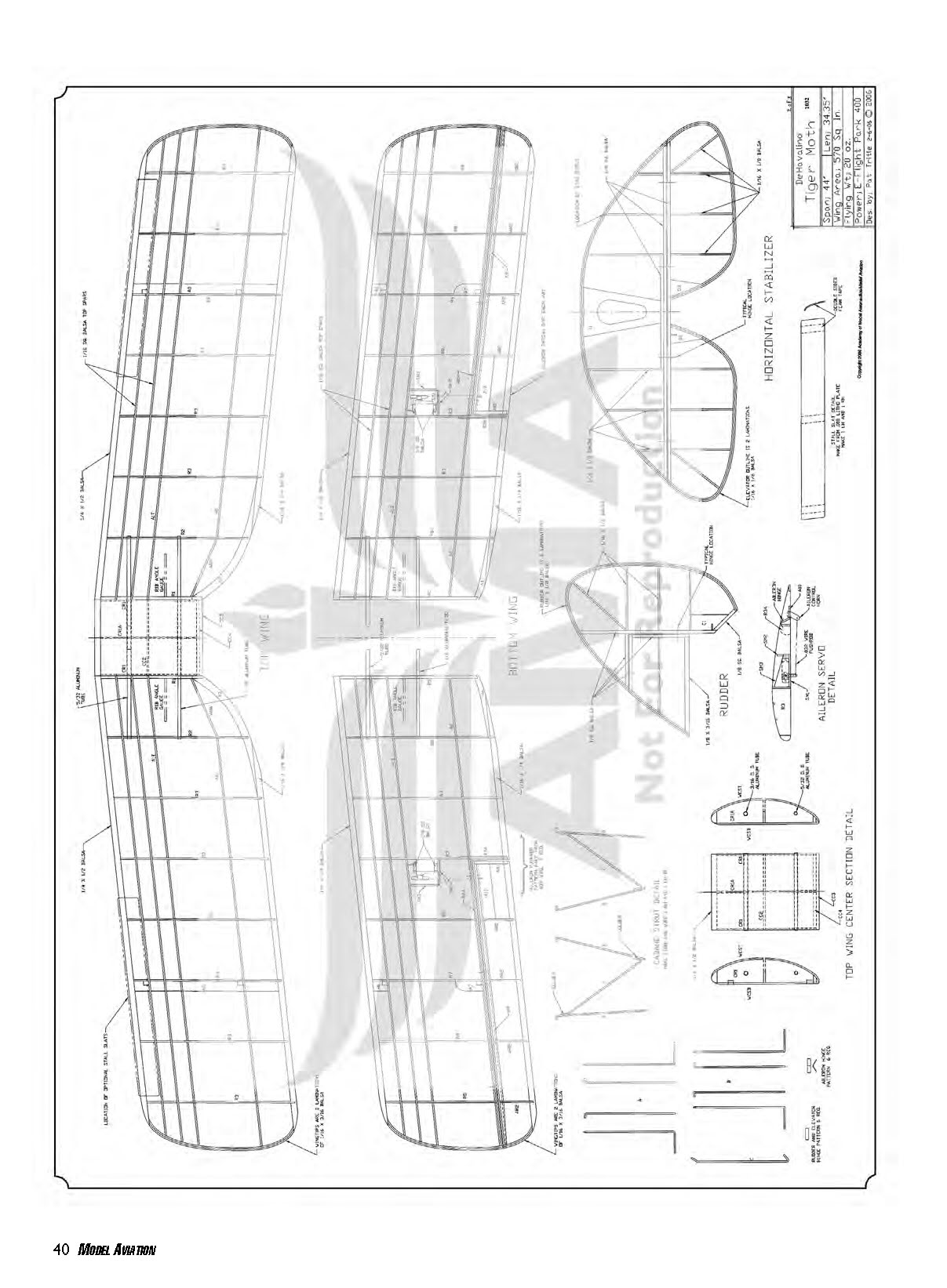
Top Wing (Center Section)
- Build the top-wing center-section directly over its bottom sheeting. Join the upper and lower sheets from parts WCST and WCSB.
- Assemble ribs and spars directly on the bottom sheeting. Glue 3/16-inch-OD and 5/32-inch-OD x 3.3-inch aluminum receiver tubes in place, leaving about 1/32-inch protruding on both sides.
- Sand the contour into the leading and trailing edges and glue the top sheeting in place.
- Remove the center-section from the board and sand to final shape. Add corrugation using your chosen method or the available plastic detail parts.
Framing the Wings (Top and Bottom Panels)
Top wing panels:
- Pin the 1/4 x 1/2 balsa leading edge (LE) and 1/16 x 1/4 balsa trailing edge (TE) in place, followed by A3 and A5.
- Adhere main spars A1T and A8 on A5, and glue ribs R2, R3, and R4.
- Use the rib angle gauge to set R1's angle and glue it in place. Trim and glue A8A, then install the 5/32-inch-OD front and 1/8-inch-OD rear 3.8-inch-long aluminum joiner tubes.
- Trim wingtip bows at the LE and TE; sand the bottom of the bow to flow into the TE from the main spars and glue in place. Fit and glue 1/16" square top spars.
- When dry, remove from the board and sand to shape.
Bottom wing panels:
- Glue A2A aileron spar doublers to A2 and R3A rib doublers to R3. Pin LE and TE and A4 in place over the plans, then add spar assemblies.
- Glue ribs R3, R6, R7, and R8 in place. Align R5 with the rib angle gauge and glue it in place.
- Install 5/32-inch-OD and 1/8-inch-OD x 3.8-inch joiner tubes.
- Trim wingtip bows, sand, and glue as with top panels. Fit and adhere 1/16" square top spars.
- Trim aileron servo-mount plate SM1 as needed and glue flush with the bottom of R3 and A1B; add support gussets SM2 and SM3.
Ailerons:
- Build the ailerons in place on the wing assembly. Glue inboard rib AR1 to A9, set the angle correctly, trim A9 to fit the tip bow, and adhere AR1 to the TE and A9 to the tip.
- Glue A10 and AR2 ribs in place. When dry, remove and sand to shape. Cut the aileron from the panel and sand.
- Cut hinge slots into the aileron spars 1/16" below the wing's top surface, angled downward about 30°. Fold hinges so the aileron holds a neutral position when installed. Refer to the Aileron Servo Detail drawing.
Wing fit and retention:
- Plug top wing panels into the center-section to check fit. There are no mechanical fasteners for the outer panels; use needle-nose pliers to gently squeeze the front mounting tubes on the outer panels slightly to create a light interference fit when plugging in.
- Use the same light interference on the bottom wings in the fuselage. A slight interference is enough to hold the wings.
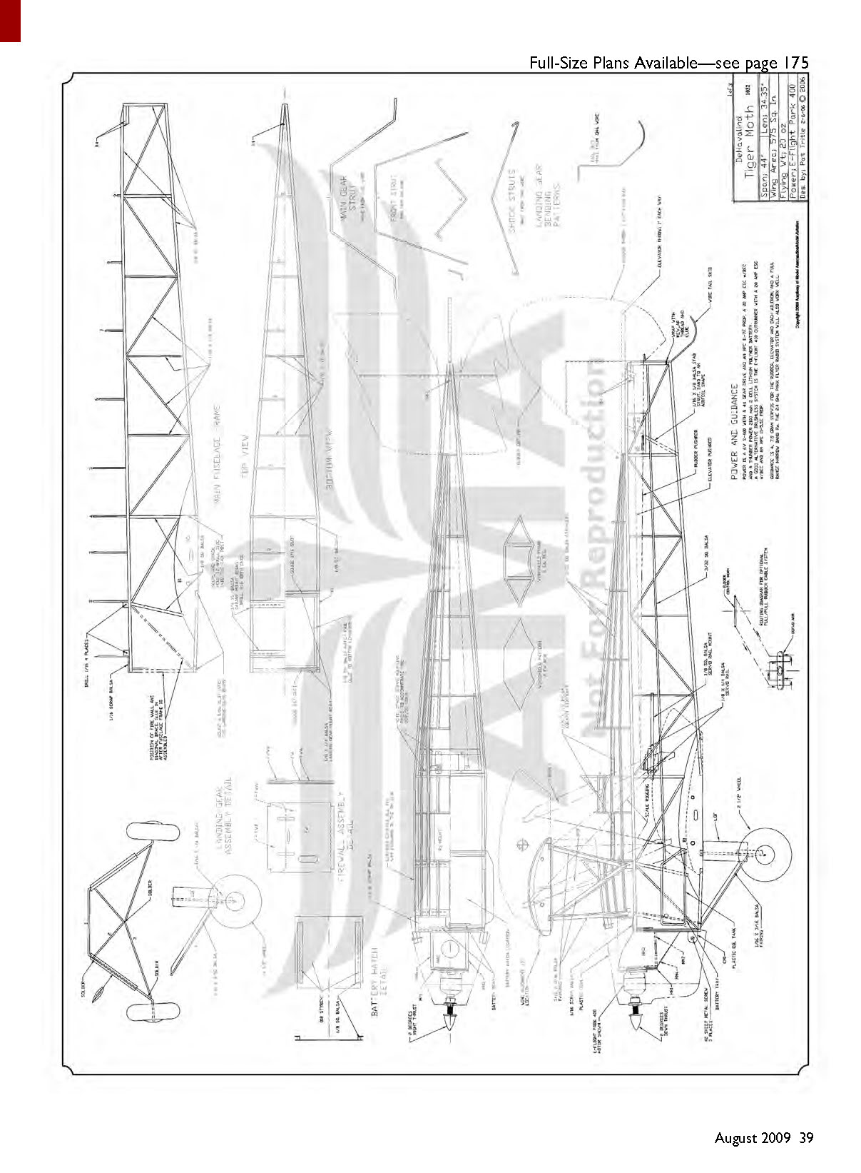
Fuselage
- Pin B1 over the Main Fuselage Frame drawing and build the frame using specified wood sizes. When dry, remove and build the second frame.
- Join fuselage frames over the top/bottom view of the framing drawing. Cut the rear landing gear-mount beam from 1/8 x 1/4 balsa and gouge a 1/16" slot down its length. Pin the landing gear mount and 1/8" square balsa crosspiece at the rear of B1.
- Score B1 on the outside edge and "crack" the side frames to angle the sides into the tail post. Adhere side frames to the mount beam and crosspiece. Use machinist squares to ensure frames are perpendicular, then add top formers 1–4 and 1/4" square balsa cabane-mount beams.
- Pull tail posts together and glue; add formers 5–9 and 1/16 x 1/8 balsa crosspieces.
- Firewall: laminate from FW, FWA, and FWB; note motor-mount slot orientation for right-hand offset. Use the Firewall Assembly Detail drawing.
- Build motor-mount assembly, glue to firewall, and install firewall on the fuselage frame using a square for alignment.
- When dry, remove frame from the board and glue 1/16 x 1/8 front diagonal braces and 3/16-inch-OD front and 5/32-inch-OD x 3.3-inch rear aluminum lower wing-mounting tubes in place.
- Cut the front landing gear-mount beam from 1/8 x 1/4 balsa, gouge a .047-inch slot, and glue in place.
- Fit and glue all 3/32" square balsa stringers on the fuselage top and sides, 1/8" square balsa hatch rails inside the front bottom longeron between the landing gear mount beams, and B4 tail-skid support blocks.
- Final framing step: make the battery hatch from .010-inch styrene and 1/8" square balsa.
Landing Gear and Cabane Struts
- Bend cabane struts from .046" wire and solder them together over the plans; make mirrored left and right assemblies. Drill cabane-mount beams with a #56 bit and fit cabanes into the fuselage.
- Main landing gear struts are bent from .062" and .046" wire. Tape front and rear struts to the fuselage frame and solder together using the Landing Gear Assembly drawing.
- Remove cabanes and landing gear from the frame. Add balsa fairings, sand to shape, and seal with two coats of water-based polyurethane varnish or dope.
- Lash landing gear to mount beams with Kevlar thread and glue. Bend the tail skid from .046" wire, lash to the tail post with Kevlar thread, and glue.
Radio and Motor Installation
- Glue 1/8" square balsa servo-rail mounts and 1/8 x 1/4 balsa servo rails in the rear cockpit. Space rails to fit the servos used and mount the servos.
- Rudder and elevator pushrods: use Sullivan Products pushrod tubes and .032" wire pushrods. Glue B2 and B3 pushrod-tube rear supports in place on the aft fuselage.
- Adhere pushrod tubes at B2 and B3 and glue provided pushrod supports at front, rear, and at least two interim locations. Use Z bends or micro easy connectors at the front end and secure to the servo arm. Leave about 2" of excess wire at the rear for final Z bends during assembly.
- If using a pull-pull rudder system, omit B2 and mount the rudder servo on the fuselage centerline. A diagram is provided for setting up pull-pull cables using a cable and a toothpick control horn. Run the cables and mark where they exit the fuselage for final assembly.
- Aileron servos are mounted in the wings with double-stick tape or silicone caulk. Extend leads to exit the wing root with 2" of slack. Center servo arms before permanently mounting.
- Mount motor on the firewall and connect the ESC. Test the system without the propeller for proper operation while components are accessible.
- Glue receiver tray between formers 2 and 3 under the front cockpit; mount the battery tray as shown behind the firewall. Use Velcro for the battery and ESC.
- Laminate, shape, and glue cowl mounting tabs; adhere using the cowl to locate them. Trim cowl and fasten with #2 sheet-metal screws.
Covering
- Sand the entire structure to remove bumps or imperfections. Clean with a damp paper towel.
- Cover with light silkspan and dope or light Mylar iron-on covering such as Nelson LiteFILM (also sold as Covelite Microlite or Solarfilm). Avoid heavy coverings like MonoKote or UltraCote, which can be too heavy and over-shrink the light structure.
- Follow the chosen covering manufacturer's recommendations.
- Prepare and paint plastic cowl and oil tank (airbrush Model Master Enamels recommended). Brush the wing center-section, landing gear, and cabanes with two coats of Model Master Acryl. Custom graphics on the prototype were made by Callie Graphics. Prep, seal, and paint or stain interplane struts at this time.
Final Assembly
- Glue aileron, elevator, and rudder hinges using Pacer Canopy 560 glue. Thin CA can make hinges too stiff, so avoid it for hinges.
- Plug the bottom wing into the fuselage and use it to align and glue the horizontal and vertical stabilizers. Ensure the elevator control-horn notch is correctly oriented.
- Set up elevator, rudder, and aileron pushrods by centering servo arms. With control surfaces neutral and control horns dry-fitted, mark and Z-bend pushrods. Fit control horns over Z bends and glue in place.
- For pull-pull rudder systems, reinforce exit points in the covering with a 1/2" square of hinge tape and cut a 1/8" slit for cable exit. Pull cables through and tie off to the control horn; secure with thin CA.
- Make a wing-alignment fixture and two wing-rigging fixtures from 3/16" foam artist's board using templates. Pin the alignment fixture on the fuselage centerline and fit the top wing onto the cabanes.
- Use interplane struts and wing-rigging fixtures to set lateral alignment. Glue the center-section atop the cabanes with five-minute epoxy and secure interplane-strut attach points with a drop of thin CA.
- Wing rigging: use 40-lb test Kevlar fishing line. Rigging runs from the top rear wing-mount tube to the bottom of each interplane strut, from the front bottom wing-mount tube to the top of each interplane strut, and an "X" between struts. Each side needs about an 84" piece of string. Wrap the string once around the front lower wing-mount tube where it comes around, slide wings out ~1", and secure the string with thin CA. Adhere .080" x 3/8" styrene rigging support "javelins" at crossover junctions with Pacer Canopy glue.
- Add final details: stabilizer support struts, windscreens, wheels, cowl, oil tank. To retain wheels, use drilled Nelson T-pin clamps to 1/16"-ID tubing, slip over axles, and secure with thin CA.
- Tail slats (optional) can be made from thin aluminum sheet (printer's litho plate used on prototype). Slats help produce slow, well-behaved landings.
- With battery mounted, set CG at 2-1/4" from the LE at the center-section. Set control throws as shown on the plans. Double-check prop rotation and control directions.
Flying
Before the maiden flight, mount a fully charged battery, recheck CG, control throws and directions, and prop rotation.
- Choose a calm day for initial trim flights.
- Takeoff: point into the breeze, hold slight up-elevator, and advance throttle to nearly two-thirds. Use rudder to keep the model straight; a bit more up-elevator may be needed if it doesn’t lift off on its own.
- Climb shallow; use rudder and ailerons together for turns. The model will turn on rudder or ailerons alone but is slow to react.
- Trim for straight and level flight at just over half throttle. The Tiger Moth is slow, smooth, and docile. Practice coordinated rudder/aileron turns.
- Try a stall: near stall speed with some power, use rudder for directional control and experiment with how slow you can fly while maintaining control.
- Landing: set up an approach carrying a bit of power. Keep the nose slightly down to avoid getting too slow. Fly to about a foot of altitude, raise the nose slightly to bleed speed, and let the airplane settle into a three-point landing as power is reduced.
- Try touch-and-goes for fun. The Tiger Moth has no major vices and is ideal for slow, relaxing park flying.
Pat Tritle [email protected]
Sources
- Laser-cut parts pack, vacuum-formed plastic parts:
- Pat's Custom Models, (505) 296-4511, [email protected]
- Callie Graphics:
- (505) 293-2922, [email protected]
- E-flite:
- (800) 338-4639, www.horizonhobby.com
- Sullivan Products:
- (410) 732-3500, www.sullivanproducts.com
- Nelson Hobby Direct:
- (877) 263-5766, www.nelsonhobby.com
- Frank Tiano Enterprises:
- (863) 607-6611, www.franktiano.com
- Model Master (Testors):
- (800) 962-6654, www.testors.com
Transcribed from original scans by AI. Minor OCR errors may remain.

