
Defensive RC Flying - 2010/08
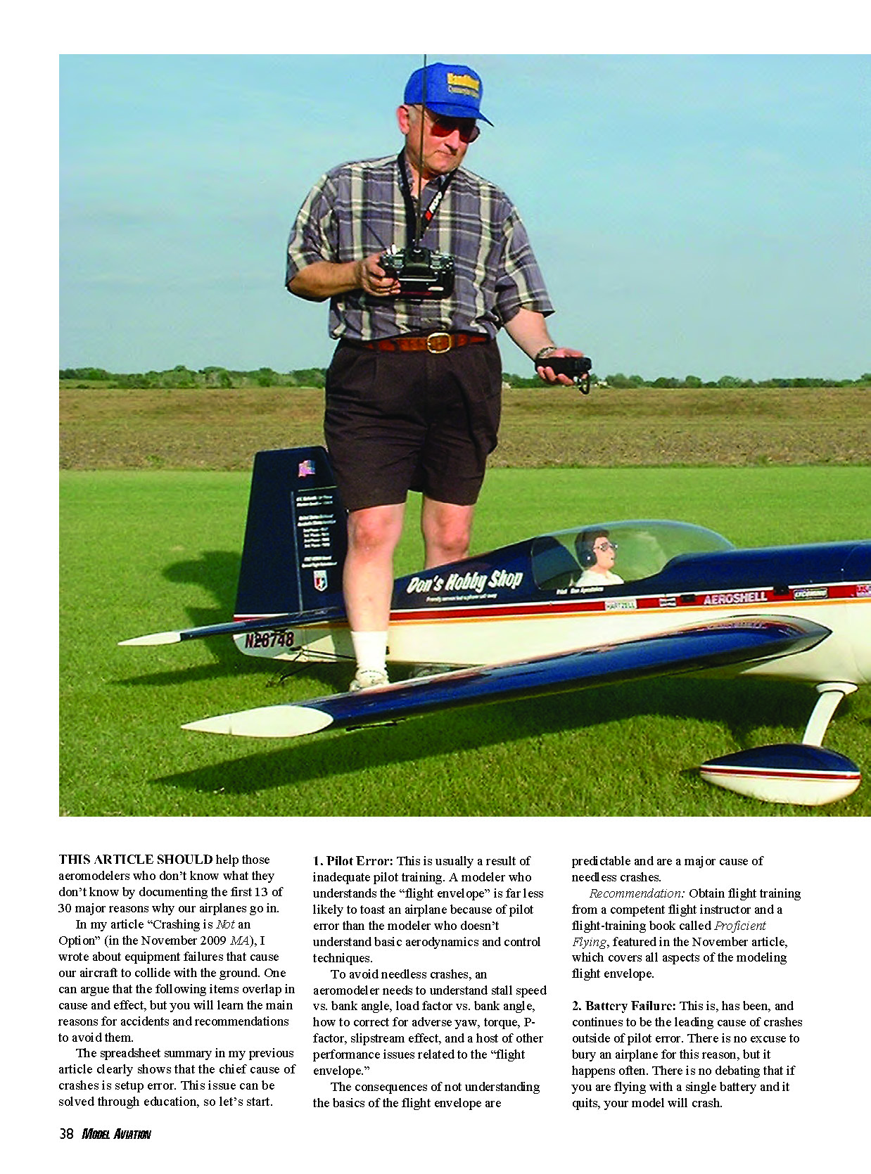
THIS ARTICLE should help those aeromodelers who don't know what they don't know by documenting the first 13 of 30 major reasons why our airplanes go in.
In my article "Crashing is Not an Option" (in the November 2009 MA), I wrote about equipment failures that cause our aircraft to collide with the ground. One can argue that the following items overlap in cause and effect, but you will learn the main reasons for accidents and recommendations to avoid them.
The spreadsheet summary in my previous article clearly shows that the chief cause of crashes is setup error. This issue can be solved through education, so let's start.
1. Pilot Error
This is usually a result of inadequate pilot training. A modeler who understands the "flight envelope" is far less likely to toast an airplane because of pilot error than the modeler who doesn't understand basic aerodynamics and control techniques.
To avoid needless crashes, an aeromodeler needs to understand stall speed vs. bank angle, load factor vs. bank angle, how to correct for adverse yaw, torque, P-factor, slipstream effect, and a host of other performance issues related to the "flight envelope."
The consequences of not understanding the basics of the flight envelope are predictable and are a major cause of needless crashes.
- Recommendation: Obtain flight training from a competent flight instructor and a flight-training book called Proficient Flying, featured in the November article, which covers all aspects of the modeling flight envelope.
2. Battery Failure
This is, has been, and continues to be the leading cause of crashes outside of pilot error. There is no excuse to bury an airplane for this reason, but it happens often. There is no debating that if you are flying with a single battery and it quits, your model will crash.
- Recommendation: Install redundant batteries and properly load-test the battery before and after every flight. This is especially important if you fly Giant Scale aircraft.
3. Switch Failure
Switches that stop working are a leading cause of crashes, following pilot error. If you fly a single switch and it fails, your airplane will crash. There is no excuse for this to cause an accident.
- Recommendation: Use redundant switches. If you fly Giant Scale, the weight of a redundant switch is negligible and immensely worthwhile.
4. Receiver Failure
Random receiver failures occur for a variety of reasons, ranging from crystal breakdown or 72 MHz receivers going into hold because of metal-to-metal contact, to aeromodelers using 7.0 volts or more unregulated voltage into receiver/servos rated for 4.8–6.0 volts only. In the past two years of troubleshooting customers' airplanes set up with 2.4 GHz systems, I have learned that 2.4 GHz receivers are not immune to ignition and electrical noise, as they were initially believed to be. Additionally, flying on a different bandwidth (2.4 GHz vs. 72 MHz) does not decrease the potential of an electrical failure on a single receiver.
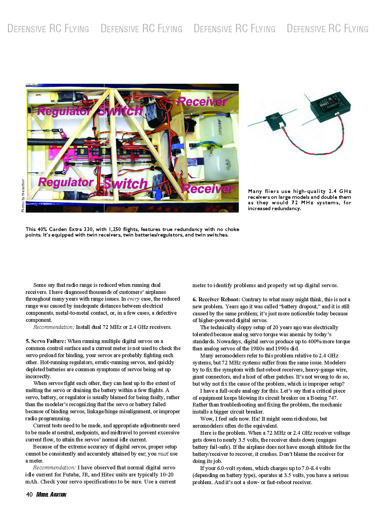
On large aircraft we carry dual receivers with the programming set to bring the throttle to idle and servos to neutral if a receiver goes into hold. If the problem is RF- or vibration-related, the receiver will usually come out of hold when the throttle is automatically retarded, which relieves the vibration and reduces the metal-to-metal or RF noise. The result is that control is often regained. If the receiver doesn't come back online, the second operational receiver allows the model to be landed.
Some say that radio range is reduced when running dual receivers. I have diagnosed thousands of customers' airplanes throughout many years with range issues. In every case, the reduced range was caused by inadequate distances between electrical components, metal-to-metal contact, or, in a few cases, a defective component.
- Recommendation: Install dual 72 MHz or 2.4 GHz receivers and ensure adequate physical separation between components to avoid metal-to-metal noise.
5. Servo Failure
When running multiple digital servos on a common control surface and a current meter is not used to check the servo preload for binding, your servos are probably fighting each other. Hot-running regulators, erratic-running servos, and quickly depleted batteries are common symptoms of servos being set up incorrectly.
When servos fight each other, they can heat up to the extent of melting the servo or draining the battery within a few flights. A servo, battery, or regulator is usually blamed for being faulty, rather than the modeler recognizing that the servo or battery failed because of binding servos, linkage/hinge misalignment, or improper radio programming.
Current tests need to be made, and appropriate adjustments need to be made at neutral, endpoints, and midtravel to prevent excessive current flow, and to attain the servos' normal idle current.
Because of the extreme accuracy of digital servos, proper setup cannot be consistently and accurately attained by ear; you must use a meter.
- Recommendation: Normal digital servo idle current for Futaba, JR, and Hitec units is typically 10–20 mA. Check your servo specifications and use a current meter to identify problems and properly set up digital servos.
6. Receiver Reboot (Battery Dropout)
Contrary to what many might think, this is not a new problem. Years ago it was called "battery dropout," and it is still caused by the same problem; it's just more noticeable today because of higher-powered digital servos.
The technically sloppy setups of 20 years ago were electrically tolerated because analog servo torque was anemic by today's standards. Nowadays, digital servos produce up to 400% more torque than analog servos of the 1980s and 1990s did.
Many aeromodelers refer to this problem relative to 2.4 GHz systems, but 72 MHz systems suffer from the same issue. Modelers try to fix the symptom with fast-reboot receivers, heavy-gauge wire, giant connectors, and a host of other patches. It's not wrong to do so, but why not fix the cause of the problem, which is improper setup?
When a 72 MHz or 2.4 GHz receiver voltage gets down to nearly 3.5 volts, the receiver shuts down (engages battery fail-safe). If the airplane does not have enough altitude for the receiver to recover, it crashes. Don't blame the receiver for doing its job.
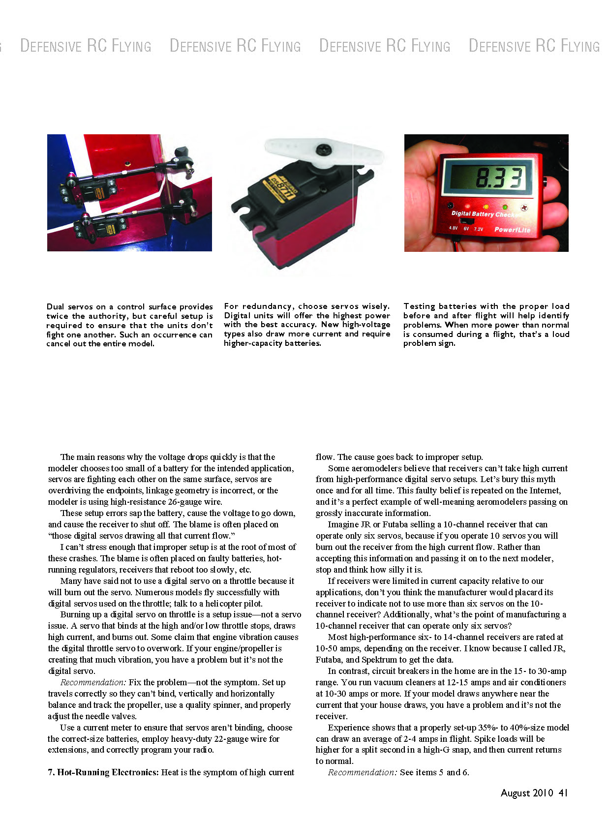
Dual servos on a control surface provide twice the authority, but careful setup is required to ensure that the units don't fight one another. For redundancy, choose servos wisely. Digital units offer the highest power with the best accuracy. New high-voltage types also draw more current and require higher-capacity batteries.
Testing batteries with the proper load before and after flight will help identify problems. When more power than normal is consumed during a flight, that's a loud problem sign.
The main reasons the voltage drops quickly are: choosing too small a battery for the intended application; servos fighting each other on the same surface; servos overdriving the endpoints; incorrect linkage geometry; or using high-resistance 26-gauge wire.
These setup errors sap the battery, cause the voltage to drop, and cause the receiver to shut off. The blame is often placed on "those digital servos drawing all that current."
- Recommendation: Fix the setup problem—not the symptom. Use a current meter to ensure servos aren't binding, choose correct-size batteries, employ heavy-duty 22-gauge wire for extensions, and correctly program your radio.
7. Hot-Running Electronics
Heat is the symptom of high current flow. The cause goes back to improper setup.
Some aeromodelers believe that receivers can't take high current from high-performance digital servo setups. This is a myth. Manufacturers design receivers for the intended applications; a 10-channel receiver is expected to operate many servos. Most high-performance six- to 14-channel receivers are rated at 10–50 amps, depending on the receiver.
If your model draws anywhere near the current that your house draws, you have a problem and it's not the receiver. Experience shows that a properly set-up 35%- to 40%-size model can draw an average of 2–4 amps in flight. Spike loads will be higher for a split second in a high-G snap, and then current returns to normal.
- Recommendation: See items 5 and 6: check for binding servos, proper linkages, appropriate battery capacity, and correct wiring.
8. Failure to Test
Would you take your family in your car on a 400-mile trip and not check the gas gauge before you leave? Of course not. But modelers frequently take off with their aircraft without first checking its electrical gas tank (battery).
If a car runs out of gas, you simply pull over. If an airplane's battery dies, it crashes.
Many aeromodelers take their power systems for granted, and that's a poor attitude. Batteries are the second-leading cause of crashes, behind pilot error.
I know the discharge curve of my batteries. When I observe a change in this curve from the norm, I make further checks and perform the appropriate maintenance.
- Recommendation: Load-test batteries before and after every flight.
9. Regulator Usage
Would you plug your new $3,000, high-definition, DLP, 60-inch LCD-screen TV rated for 110.0 volts into a 220.0-volt socket and then wonder why it doesn't work? Modelers do the equivalent with radio gear by installing a 7.0-volt or higher battery in a radio rated for 6.0 volts.
Some popular servos are rated for only 4.8 volts, with most rated for up to 6.0. If a modeler uses a 6.0-volt battery without a regulator, servos and receivers might not work or work intermittently because they are being overdriven with too much voltage.
The term "6.0-volt battery" is misleading, because 6.0-volt Ni-Cd and NiMH batteries charge to higher than 7.0 volts and Lithium types exceed 8.0 volts. Servos rated for 4.8 volts only can't take 6.0 volts, even if used with a regulator. Check your servo specifications and set the regulator correctly.
A regulator is used to step down high voltage so that the electronics can operate within the manufacturer's specified range. The regulator goes after the switch and plugs into the receiver. Failure to place the regulator in the correct place will lead to a crash; you can't back-charge through most regulators because of the diode.
- Recommendation: When using a 6.0-volt Ni-Cd, NiMH, or Lithium battery, employ a regulator and correctly set the output based on the lowest recommended-voltage component on the model.
10. Poor Power-System Balance
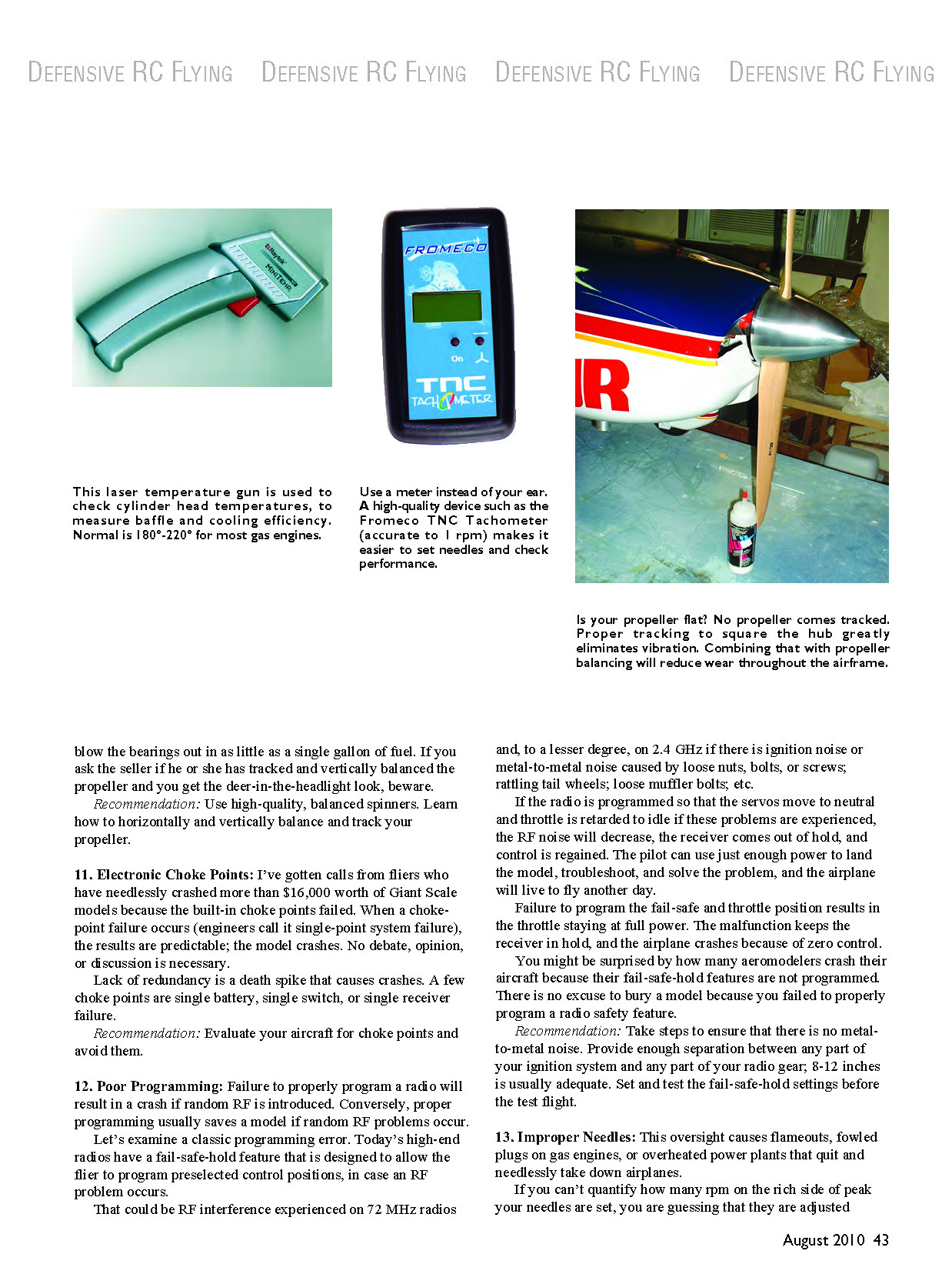
Would you buy new tires and not have them balanced? Improperly setting up propellers and spinners is a common source of vibration. Many aeromodelers fly with unbalanced propellers and spinners and untracked propellers.
Propeller tracking is the process used to square the propeller hub so that the blades are perpendicular to the crankshaft. Unbalanced spinners or vibrating propellers induce vibration in the model, placing stress on electrical components, hinges, and glue joints, and the engine is often blamed for being a "shaker."
This constant pounding of the airframe can eventually trigger electrical component, structural, or hinge failure. Cause and effect of the crash are often overlooked, with blame placed on the servo or switch that failed.
Beware of used engines. A pilot who has operated an engine with an unbalanced or untracked propeller and/or unbalanced spinner can blow the bearings out in as little as a single gallon of fuel. If you ask the seller if he or she has tracked and vertically balanced the propeller and you get the deer-in-the-headlight look, beware.
- Recommendation: Use high-quality, balanced spinners. Learn how to horizontally and vertically balance and track your propeller.
11. Electronic Choke Points
I’ve gotten calls from fliers who have needlessly crashed more than $16,000 worth of Giant Scale models because built-in choke points failed. When a choke-point failure occurs (engineers call it single-point system failure), the results are predictable: the model crashes.
Lack of redundancy is a death spike that causes crashes. A few choke points are single battery, single switch, or single receiver failure.
- Recommendation: Evaluate your aircraft for choke points and eliminate them where possible by adding redundancy.
12. Poor Programming
Failure to properly program a radio will result in a crash if random RF is introduced. Conversely, proper programming usually saves a model if random RF problems occur.
Today’s high-end radios have a fail-safe-hold feature that allows the flier to program preselected control positions in case an RF problem occurs. That could be RF interference experienced on 72 MHz radios and, to a lesser degree, on 2.4 GHz if there is ignition noise or metal-to-metal noise caused by loose nuts, bolts, or screws; rattling tail wheels; loose muffler bolts; etc.
If the radio is programmed so that the servos move to neutral and throttle is retarded to idle when these problems are experienced, the RF noise will decrease, the receiver will come out of hold, and control is often regained. The pilot can use just enough power to land the model, troubleshoot, and solve the problem.
Failure to program the fail-safe and throttle position results in the throttle staying at full power. The malfunction keeps the receiver in hold, and the airplane crashes because of zero control.
You might be surprised by how many aeromodelers crash their aircraft because their fail-safe-hold features are not programmed. There is no excuse to lose a model because you failed to properly program a radio safety feature.
- Recommendation: Provide enough separation between any part of your ignition system and any part of your radio gear (8–12 inches is usually adequate). Set and test the fail-safe and hold settings before the test flight.
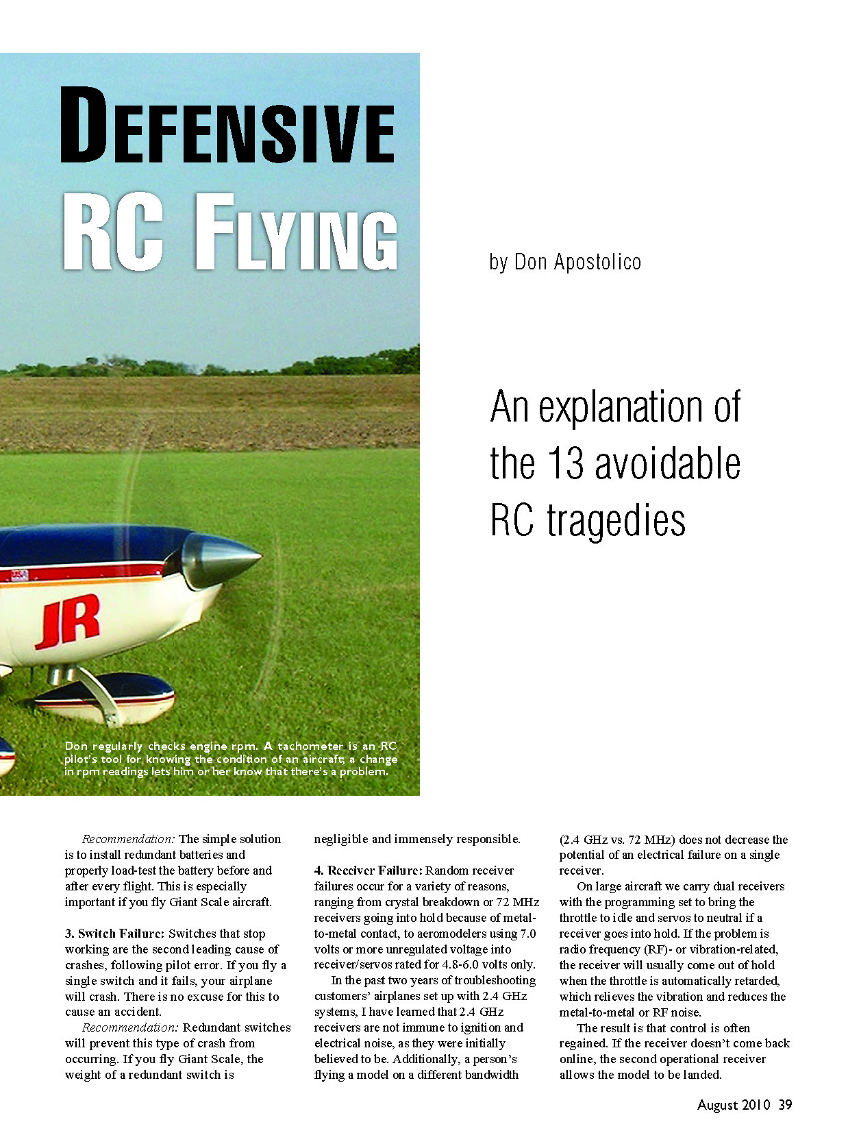
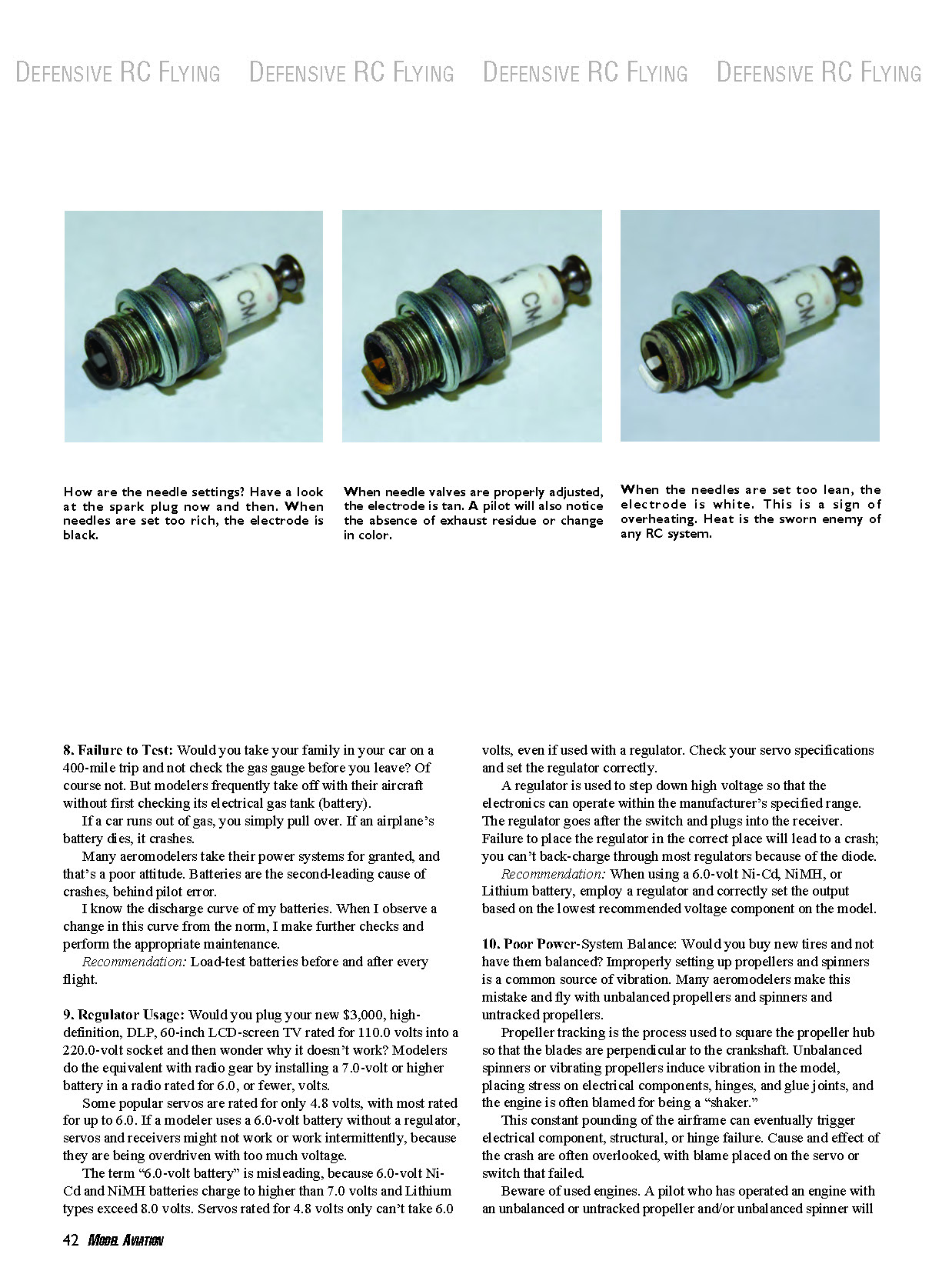
13. Improper Needles
This oversight causes flameouts, fouled plugs on gas engines, or overheated power plants that quit and needlessly take down airplanes.
If you can’t quantify how many rpm on the rich side of peak your needles are set, you are guessing that they are adjusted correctly. A tachometer is the only way to be sure. Today’s high-performance engines and mufflers make it hard to judge power by ear. The remedy is a high-quality tachometer. It is worth its weight in gold.
You might guess right from time to time, but the most common complaint with gas engines is that they vibrate, have an erratic midrange, and run roughly. The most common reason for the latter or hard starting is misadjusted needle valves. Because you turn the needles doesn't mean they are correctly adjusted. The engine might run, but not as it should.
Using the old pinch test, the high and low end on a two- or four-stroke glow engine are typically adjusted 200 rpm on the rich side of peak. A gas engine is typically adjusted 100 rpm on the rich side of peak, with the exception of the BME 110/116; it's set 200 rpm on the rich side of peak.
Assuming that baffling and inlet or exit area ratios are correct, these will be close to the final flight settings. You will make final microadjustments with flight tests. If these settings are far from your final flight settings, there are other issues you need to address.
The spark plug is a good barometer of your needle setting. The electrode should be tan in color. If it's black, the setting is too rich; if it's white, the setting is too lean.
Another needle-adjustment issue is related to those who say that two- and four-stroke engines run poorly inverted. If two- and four-stroke power plants didn't run well inverted, virtually every competition RC Aerobatics model in the world wouldn't be configured that way. They run fine inverted.
- Recommendation: Don't guess. Use a quality tachometer and precisely set needles (use the pinch test as a starting point) and ensure your fuel system is set up properly.
Throughout the many years I have owned Don's Hobby Shop, I have spoken to tens of thousands of people, solved problems, and helped customers set up and equip their aircraft. In the process, I have learned that there are no new reasons why models crash; those causes were identified many years ago.
Since we know the why, crash avoidance is not difficult. However, the aeromodeler must learn what the issues are to avoid the problems and apply the fixes.
The remaining causes of crashes will be featured in a future article. Until then, your challenge is to apply the information I have presented to your circumstances so you can fly safely and with confidence.
MA
Don Apostolico [email protected]
August 2010
Transcribed from original scans by AI. Minor OCR errors may remain.

