
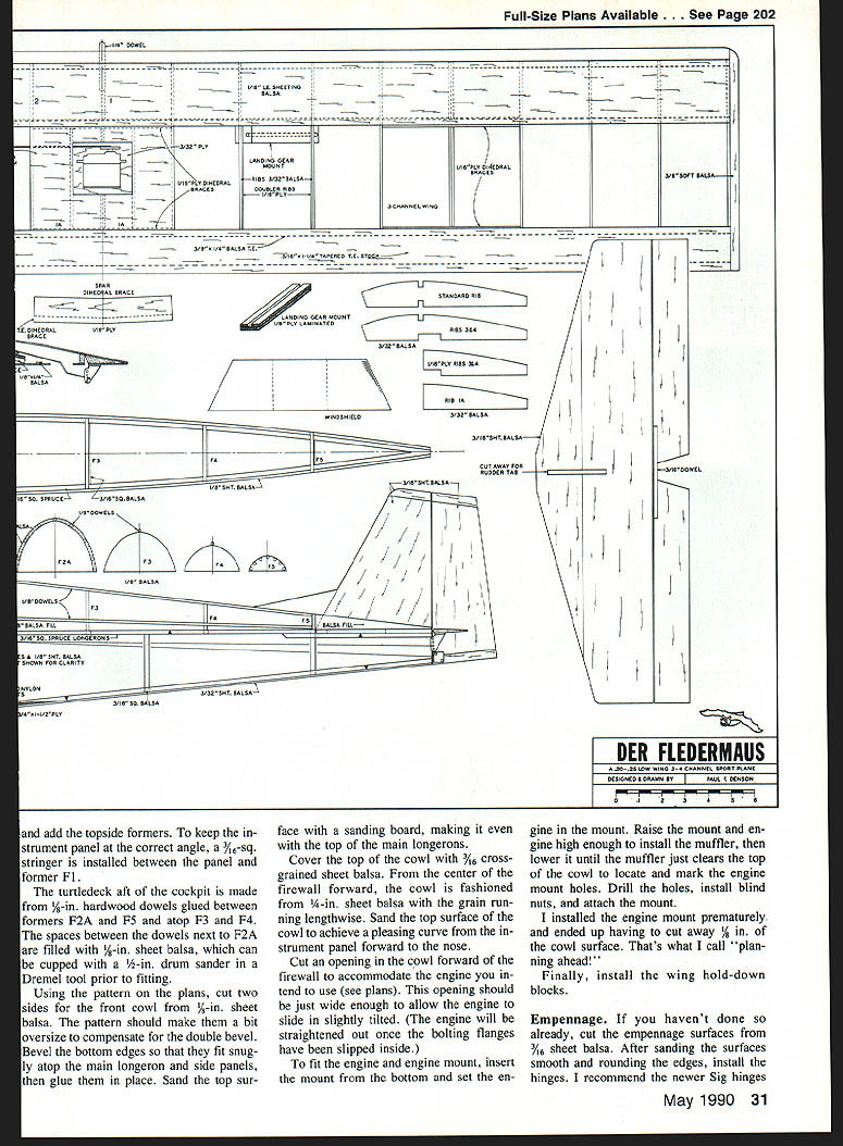
Der Fle
Paul F. Denson
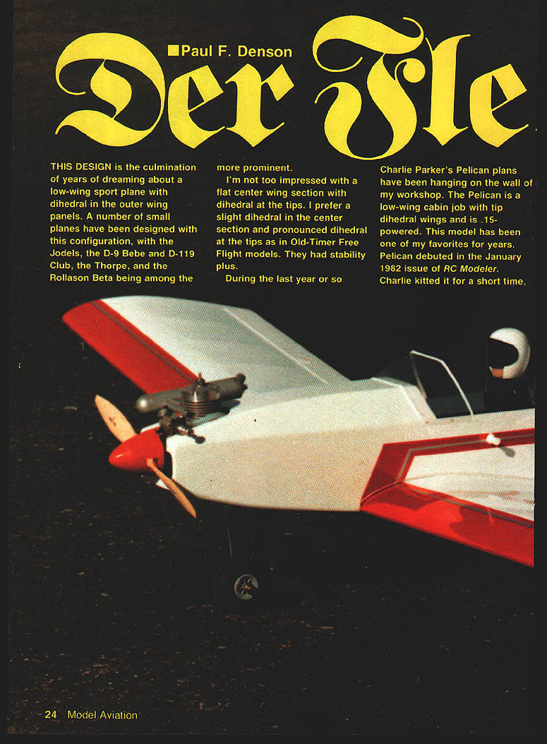
THIS DESIGN is the culmination of years of dreaming about a low‑wing sport plane with dihedral in the outer wing panels. A number of small planes have been designed with this configuration, with the Jodels, the D‑9 Bebe and D‑119 Club, the Thorpe, and the Rollason Beta among the more prominent.
I'm not too impressed with a flat center wing section with dihedral at the tips. I prefer a slight dihedral in the center section and pronounced dihedral at the tips as in Old‑Timer free‑flight models. They had stability plus.
During the last year or so Charlie Parker's Pelican plans have been hanging on the wall of my workshop. The Pelican is a low‑wing cabin job with tip‑dihedral wings and is .15‑powered. This model has been one of my favorites for years. Pelican debuted in the January 1982 issue of RC Modeler. Charlie kitted it for a short time, but as far as I know no kits are available today.
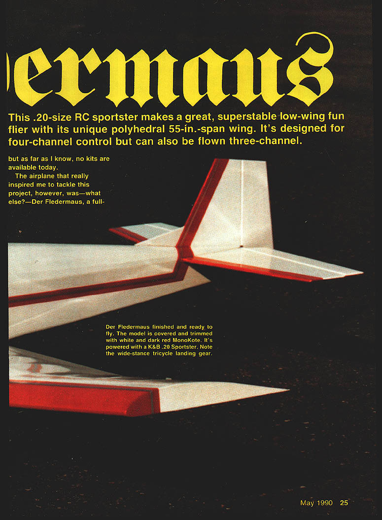
This .20‑size RC sportster makes a great, superstable low‑wing fun flier with its unique polyhedral 55‑in.‑span wing. It's designed for four‑channel control but can also be flown three‑channel.
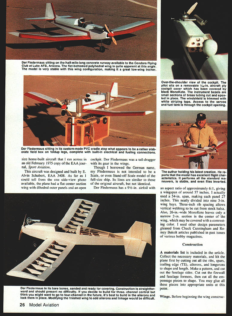
The airplane that really inspired me to tackle this project, however, was—what else?—Der Fledermaus, a full‑size home‑built aircraft that I ran across in an old February 1975 copy of the EAA journal Sport Aviation. This aircraft was designed and built by E. Alvin Schubert, EAA 3408. As far as I could tell from the one side‑view photo available, the plane had a flat center‑section wing with dihedral outer panels and an open cockpit. Der Fledermaus was a tail‑dragger with its gear in the wings.
Though I borrowed the German name, my Fledermaus is not intended to be a scale, or even stand‑off scale, model of the full‑size ship. Its lines are similar to those of the original aircraft, but not identical.
Der Fledermaus has a 9‑1/2‑in. chord wing section with an aspect ratio of approximately 6:1, which would give a wingspan of around 57 in. I actually used a 54‑in. span, making each panel 27 in. This neatly divided into nine 3‑in. wing bays. Three‑inch rib spacing allows vertical webbing to be cut from stock balsa. Also, 26‑in.‑wide MonoKote leaves only a narrow 2‑in. section in the center of the wing, which may be covered with a contrasting color. I used other design parameters gleaned from Chuck Cunningham and Romey Bukolt articles published in past issues of various hobby magazines.
Construction
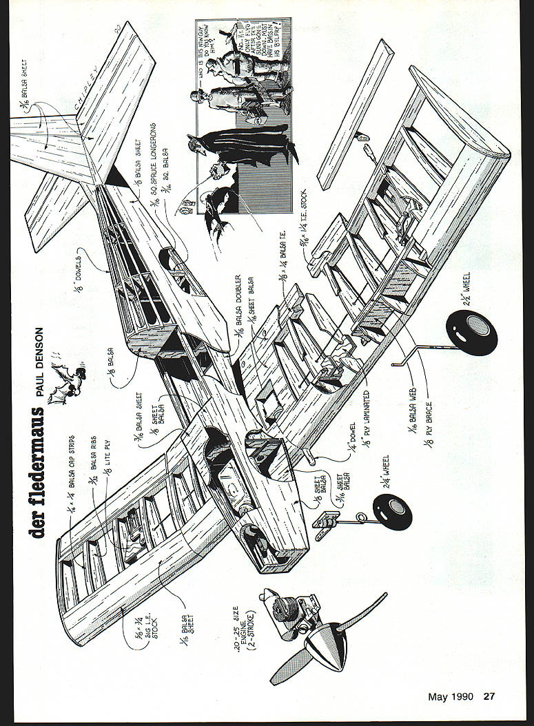
A materials list is included below. Kit the plane first by cutting out all the ribs, spars, trailing edge (TE), ailerons, and longerons to shape and length. Make a pattern and cut out the fuselage sides. Cut out the firewall and fuselage formers, then cut all the empennage pieces to shape. You may glue all these pieces into appropriate units at this point.
Wings
Before beginning wing construction, decide whether you want three‑ or four‑channel control. Der Fledermaus is designed as an aileron trainer and will fly beautifully with rudder/elevator control. If you really want to build three‑channel but think you might convert later, build the aileron version and lock the ailerons in place. Modifying a finished wing to add ailerons and linkage would be difficult.
Note: installing Sig symmetrical leading‑edge (LE) stock at an angle on flat‑bottomed wings originated with Doc Mathews' My‑O‑My. It works great. Thanks, Doc!
Begin construction of each section by pinning the bottom 1/4‑in.‑sq. spruce spar to the plans (use waxed paper or Saran wrap between plan and structure). Using the ribs as spacers, pin the 1/4 x 1/2‑in. TE stock to the plan. Insert all the ribs except the two center ribs and the two dihedral joint ribs. Glue the top spar and the LE in place. When installing the LE, maintain a 1/16‑in. overlap at the top and bottom to allow for fitting the LE sheeting.
Install the 3/32 x 1‑1/4‑in. TE fillers on the four wing panels. If installing ailerons on the outboard panels, pin the TE filler stock (which will become the ailerons) in position through the TE. Use no glue on the center line. Sand the TE to fair in with the tapered TE filler.
Some photos show triangular fillets between the TE and the ribs. I found that using cap strips rendered these fillets unnecessary.
When all four panels are structurally complete, join them into one polyhedral unit. Leave one inboard panel pinned to the building board, and prop up one outboard panel to measure 1‑1/2 in. from the board surface at the wing tip. Check the dihedral joint fit and sand it to the correct bevel. Epoxy the 1/16‑in. ply spar and TE dihedral braces in place, making sure to maintain the correct angle and alignment while curing. Don't glue the TE filler butt joints. Fit and glue the dihedral joint ribs in place. Repeat the same procedure for the other inboard and outboard panels.
Assemble the two wing halves by pinning one inboard panel to the building board, then propping up the other to measure 1‑1/2 in. from the board surface at the polyhedral joint. Sand the upper and lower spars and the LE and TE butts for a snug fit. Double‑check alignment and angle, pin the spars and LE and TE butts in place, and glue them together. When cured, clamp the spar and TE ply dihedral braces in place, making sure they don't protrude above or below the upper and lower spars. Once satisfied with the fit, epoxy the braces in place.
Cut and fit the vertical‑grain webbing, then glue it in place.
Trim the 1/16 x 2‑in. balsa inboard and outboard TE sheeting (top and bottom) to length, and epoxy in place. Mark a line on the outboard TE sheeting to show where to separate the aileron.
Glue the two center wing (No. 1) ribs together. When dry, cut to fit and glue in place. Add the 1/8 x 2‑3/4‑in. balsa upper LE sheeting, gluing it snugly to the LE spar.
Install the bottom LE sheeting and add the bottom center sheeting.
Install the 1/8‑in. aileron ribs, positioning them in accordance with the size of your servo. Cut and fit the 3/32‑in. ply servo mount between these ribs. Set the wing aside until later.
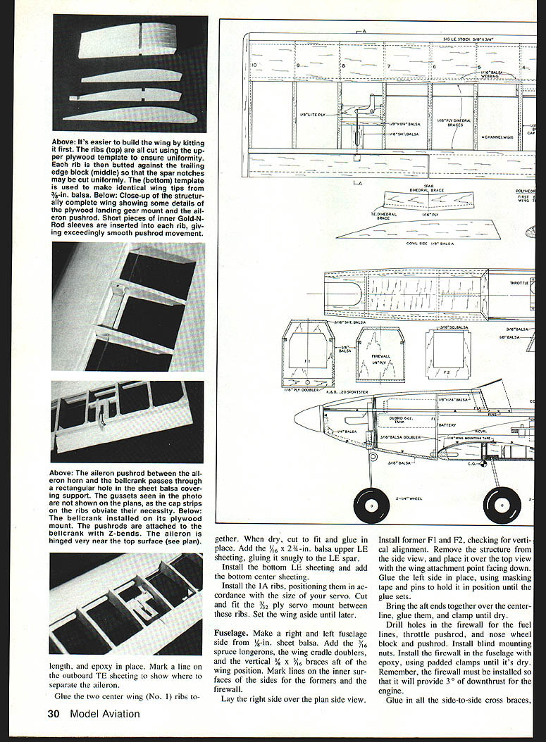
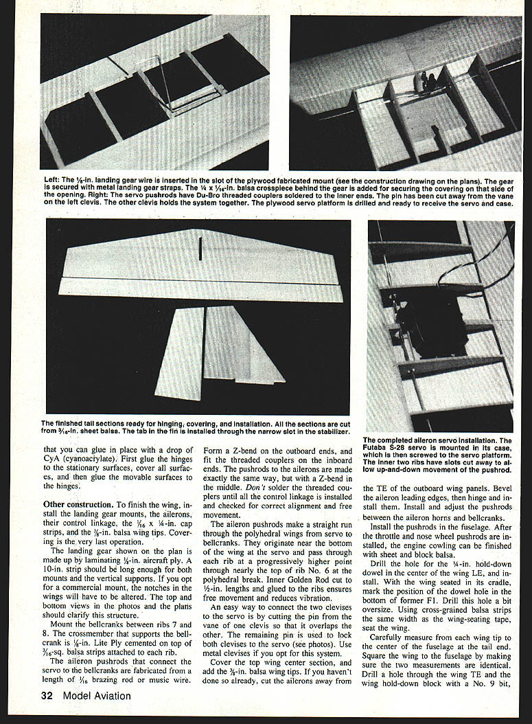
The aileron pushrods that connect the servo to the bellcranks are fabricated from a length of 1/8‑in. brazing rod or music wire. Form a Z‑bend on the outboard ends, and fit the threaded couplers on the inboard ends. The pushrods to the ailerons are made exactly the same way, but with a Z‑bend in the middle. Don't solder the threaded couplers until all the control linkage is installed and checked for correct alignment and free movement.
The aileron pushrods make a straight run through the polyhedral wings from servo to bellcranks. They originate near the bottom of the wing at the servo and pass through each rib at a progressively higher point, through nearly the top of rib No. 6 at the polyhedral break. Inner Goldenrod tubing, cut to 1/2‑in. lengths and glued to the ribs, ensures free movement and reduces vibration.
An easy way to connect the two clevises to the servo is by cutting the pin from one of the clevises so that it overlaps the other. The remaining pin is used to lock both clevises to the servo. Use metal clevises if you opt for this system.
Cover the top wing center section, and add the 3/16‑in. balsa wing tips. If you haven't done so already, cut the ailerons away from the TE of the outboard wing panels. Bevel the aileron leading edges, then hinge and install them. Install and adjust the pushrods between the aileron horns and bellcranks.
Install the landing gear mounts and the 1/16 x 1/4‑in. cap strips. Covering is the very last operation.
Mount the bellcranks between ribs 7 and 8. The crossmember that supports the bellcrank is 5/16‑in. lite ply cemented on top of 3/16‑in. balsa strips attached to each rib.
Drill the hole for the 1/4‑in. hold‑down dowel in the center of the wing LE, and install it. With the wing seated in its cradle, mark the position of the dowel hole in the bottom of former F1. Drill this hole a bit oversize. Using cross‑grained balsa strips the same width as the wing‑seating tape, seal the wing.
Carefully measure from each wing tip to the center of the fuselage at the tail end. Square the wing to the fuselage by making sure the two measurements are identical. Drill the mounting hole through the wing TE and the wing hold‑down block with a No. 9 bit, then thread the block with a 1/4‑20 tap. Check the threads with a 1/4‑20 nylon bolt, then apply a drop of CyA into both the wing and block holes and retap. Ream out the wing hole to a 1/4‑in. diameter.
Drill a 1/4‑in.‑dia. hole in the center of a 1/2‑in. strip of 2‑3/4‑in.‑long 3/32‑in. ply. Place this strip over the end of the wing hold‑down dowel on the forward side of former F1, and epoxy it in place. Remove the wing before the epoxy sets up.
Fuselage
Make a right and left fuselage side from 1/8‑in. sheet balsa. Add the 1/8‑in. spruce longerons, the wing cradle doublers, and the vertical 3/32 x 3/16‑in. braces aft of the wing position. Mark lines on the inner surfaces of the sides for the formers and the firewall.
Lay the right side over the plan side view. Install former F1 and F2, checking for vertical alignment. Remove the structure from the side view, and place it over the top view with the wing attachment point facing down. Glue the left side in place, using masking tape and pins to hold it in position until the glue sets.
Bring the aft ends together over the centerline, glue them, and clamp until dry.
Drill holes in the firewall for the fuel lines, throttle pushrod, and nose‑wheel lock and pushrod. Install blind mounting nuts. Install the firewall in the fuselage with epoxy, using padded clamps until it's dry. The firewall must be installed so that it will provide 3° of downthrust for the engine.
Glue in all the side‑to‑side cross braces and add the topside formers. To keep the instrument panel at the correct angle, install a 3/16‑in.‑sq. stringer between the panel and former F1.
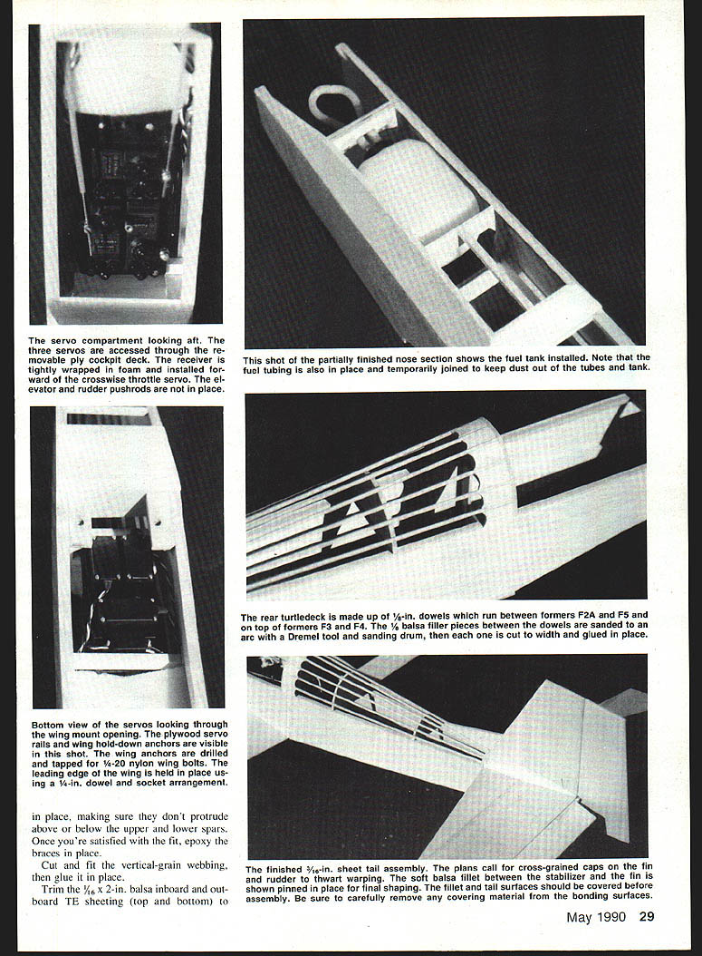
The turtledeck aft of the cockpit is made from 1/8‑in. hardwood dowels glued between formers F2A and F5 and atop F2 and F4. The spaces between the dowels next to F2A are filled with 1/8‑in. sheet balsa, which can be cupped with a 1/2‑in. drum sander in a Dremel tool prior to fitting.
Using the pattern on the plans, cut two sides for the front cowl from 1/8‑in. sheet balsa. The pattern should make them a bit oversize to compensate for the double bevel. Bevel the bottom edges so they fit snugly atop the main longeron and side panels, then glue them in place. Sand the top surface with a sanding board, making it even with the top of the main longerons.
Cover the top of the cowl with 3/16‑in. cross‑grained sheet balsa. From the center of the firewall forward, the cowl is fashioned from 1/4‑in. sheet balsa with the grain running lengthwise. Sand the top surface of the cowl to achieve a pleasing curve from the instrument panel forward to the nose.
Cut an opening in the cowl forward of the firewall to accommodate the engine you intend to use (see plans). This opening should be just wide enough to allow the engine to slide in slightly tilted. (The engine will be straightened out once the bolting flanges have been slipped inside.)
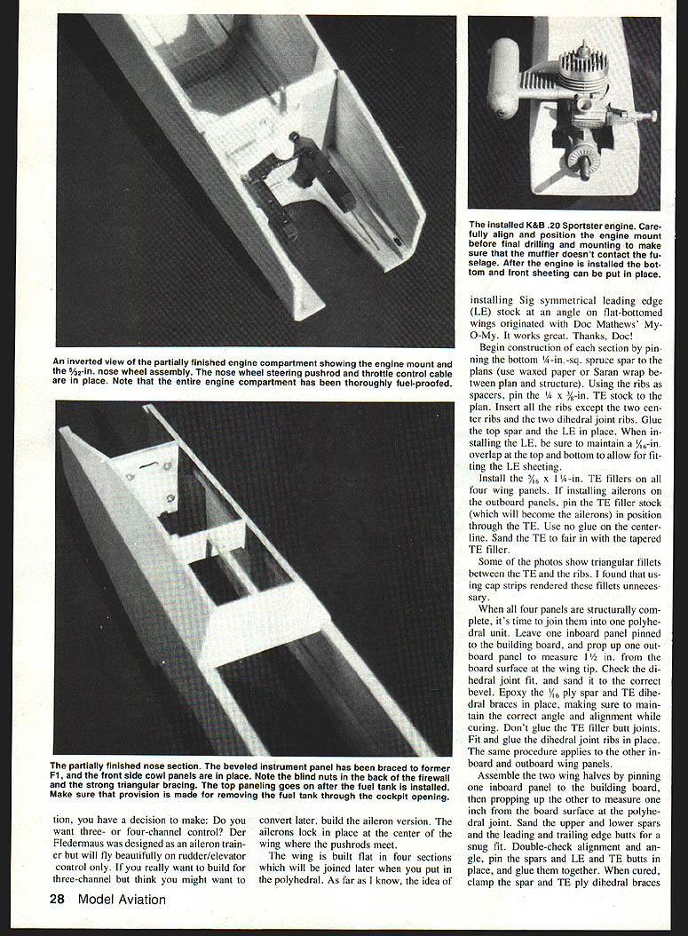
To fit the engine and engine mount, insert the mount from the bottom and set the engine in the mount. Raise the mount and engine high enough to install the muffler, then lower it until the muffler just clears the top of the cowl to locate and mark the engine mount holes. Drill the holes, install blind nuts, and attach the mount.
Finally, install the wing hold‑down blocks.
Empennage
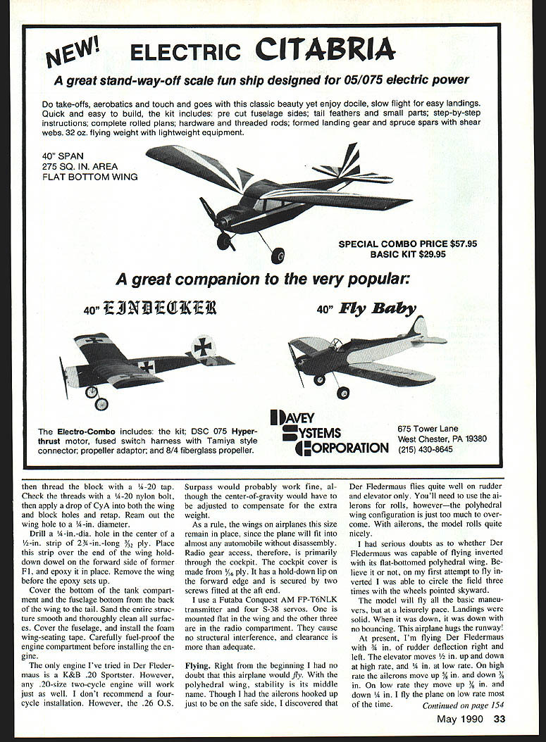
Cut the empennage surfaces from 3/16‑in. sheet balsa. After sanding the surfaces smooth and rounding the edges, install the hinges. I recommend the newer Sig hinges that you can glue in place with a drop of CyA. First glue the hinges to the stationary surfaces, cover all surfaces, and then glue the movable surfaces to the hinges.
Other construction tasks: finish the wing by installing the landing gear mounts, the ailerons and their control linkage, the cap strips, and the balsa wing tips. Covering is the last operation.
The landing gear shown on the plans is made by laminating 1/8‑in. aircraft ply. A 10‑in. strip should be long enough for both mounts and the vertical supports. If you opt for a commercial mount, the notches in the wings will have to be altered. The top and bottom views in the photos and the plans clarify this structure.
Install the pushrods in the fuselage. After the throttle and nose‑wheel pushrods are installed, the cowl and nose cowl can be finished with sheet and block balsa.
Cover the bottom of the tank compartment and the fuselage bottom from the back of the wing to the tail. Sand the entire structure smooth and thoroughly clean all surfaces. Cover the fuselage, and install the foam wing‑seating tape. Carefully fuel‑proof the engine compartment before installing the engine.
The only engine I've tried in Der Fledermaus is a K&B .20 Sportster. However, any .20‑size two‑cycle engine will work just as well. I don't recommend a four‑cycle installation. The .26 O.S. Surpass would probably work fine, although the center‑of‑gravity would have to be adjusted to compensate for the extra weight.
As a rule, the wings on airplanes this size remain in place, since the plane will fit into almost any automobile without disassembly. Radio gear access, therefore, is primarily through the cockpit. The cockpit cover is made from 1/8‑in. ply. It has a hold‑down lip on the forward edge and is secured by two screws fitted into the aft end.
I use a Futaba Conquest AM FP‑6TNLK transmitter and four S‑38 servos. One is mounted flat in the wing and the other three are in the radio compartment. They cause no structural interference, and clearance is more than adequate.
Flying
Right from the beginning I had no doubt that this airplane would fly. With the polyhedral wing, stability is its middle name. Though I had the ailerons hooked up just to be on the safe side, I discovered that Der Fledermaus flies quite well on rudder and elevator only. You'll need to use the ailerons for rolls; however, the polyhedral wing configuration is just too much to overcome. With ailerons, the model rolls quickly.
I had serious doubts as to whether Der Fledermaus was capable of flying inverted with its flat‑bottomed polyhedral wing. Believe it or not, on my first attempt to fly inverted I was able to circle the field three times with the wheels pointed skyward. The model will fly all the basic maneuvers, but at a leisurely pace. Landings were solid. When it was down, it was down with no bouncing. This airplane hugs the runway!
At present, I'm flying Der Fledermaus with 3/8 in. of rudder deflection right and left. The elevator moves 1/2 in. up and down at the high rate, and 1/4 in. at low rate. On high rate the ailerons move 1/2 in. up and down, and 3/8 in. on low rate. On low rate they move 3/8 in. up and 1/4 in. down. I fly the plane on low rate most of the time.
If your radio doesn't have dual rates, set the control surface movement somewhere between the high and low settings indicated above. Differential movement on the ailerons is not necessary.
This rock‑stable trainer will bring you as much building and flying fun as it's given me.
Specifications
- Wingspan: 55‑1/8 in.
- Wing chord: 9‑1/2 in.
- Wing area: 524 sq. in.
- Wing loading: 16.6 oz./sq. ft.
- Elevator span: 20 in.
- Elevator chord: 5‑3/16 in.
- Average elevator area: 115 sq. in.
- Fin/rudder height: 36 in.
- Fin/rudder width: 5‑1/2 in.
- Fuselage length: 36 in.
- Radio compartment: 9‑1/2 in. long by 2‑1/2 in. high by 2‑1/2 in. wide
- Recommended engine sizes: .20‑.25 two‑stroke, .26 four‑stroke
- Fuel tank: 6 oz.
- Landing gear: tricycle
- Radio channels: three or four (ailerons, elevator, rudder, throttle)
- Weight ready to fly: 3‑1/2 lb. (60 oz.)
Parts list
- Six 1/4 x 3 x 36‑in. balsa sheets for wing sheeting
- Three 3/32 x 3 x 36‑in. balsa sheets for wing ribs and fuselage bottom
- Three 1/4 x 3 x 36‑in. balsa sheets for front decking, aft turtledeck formers, and fuselage sides
- Two 1/16 x 3 x 36‑in. balsa sheets for rudder, fin, elevator, and fuselage bottom
- Four 1/8 x 3 x 36‑in. spruce sticks for fuselage longerons
- Four 1/8 x 3 x 36‑in. spruce sticks for wing spars
- Two pieces of 3/8 x 3/4 x 36‑in. Sig LE stock for the wing LE
- Two pieces of 1/8 x 1/4 x 36‑in. tapered balsa stock for the wing TE filler
- Two 1/8 x 1/4 x 36‑in. balsa sticks for the wing TE spars
- One 8‑in. long length of 3/8‑in. triangular stock for the firewall doubler
- One piece of 1/8‑in. aircraft ply for the wing dihedral braces
- One piece of 1/16‑in. lite ply for the fuse formers and the bellcrank supports in the wings
- One piece of 1/4‑in. aircraft ply to doubler F1
- One piece of 1/8‑in. aircraft ply for the servo doubler in the wing
- One piece of 1/8‑in. aircraft ply for the engine mount/firewall
- One 5/8‑in.‑dia. x 36‑in.‑long length of hardwood doweling for the turtledeck
- One 1/4‑in.‑dia. x 3/4‑in.‑long piece of hardwood doweling for the wing hold‑down
- One length of 1/8 x 36‑in. music wire for the landing gear
- One 5/32‑in. front landing gear assembly and accessories
- Two 2‑1/2‑in. wheels for the main landing gear
- One 2‑in. wheel for the nose gear
- One 6‑oz. Du‑Bro (or equivalent) fuel tank
- Assorted nuts, bolts, machine screws, sheet metal screws, clevises, threaded connectors, pushrod ends, 1/8‑in. brazing or music wire, 1/4‑20 nylon wing hold‑down bolts, and Gold‑N‑Rod pushrods
- One .20‑.25 two‑stroke engine
- Appropriate glues, fillers, covering materials, and any sundry items and merchandise that may have been forgotten
Begin construction by pinning the bottom 1/8‑in.‑sq. spruce spar to the plans; use waxed paper or Saran wrap between the plan and the structure. Using rib spacers, pin the TE stock to the plan. Insert ribs except the two center ribs and the two dihedral joint ribs. Glue top spar and LE in place, making sure to maintain a 1/16‑in. overlap top and bottom to allow fitting LE sheeting. Install 1/8 x 1/4‑in. TE fillers in the four wing panels; when installing ailerons in the outboard panels, pin the TE filler stock that will become the ailerons, positioning through the TE. Use no glue on the center line. Sand TE fairing tapered TE filler. When the four panels are structurally complete, join the polyhedral unit as described above.
Transcribed from original scans by AI. Minor OCR errors may remain.

