
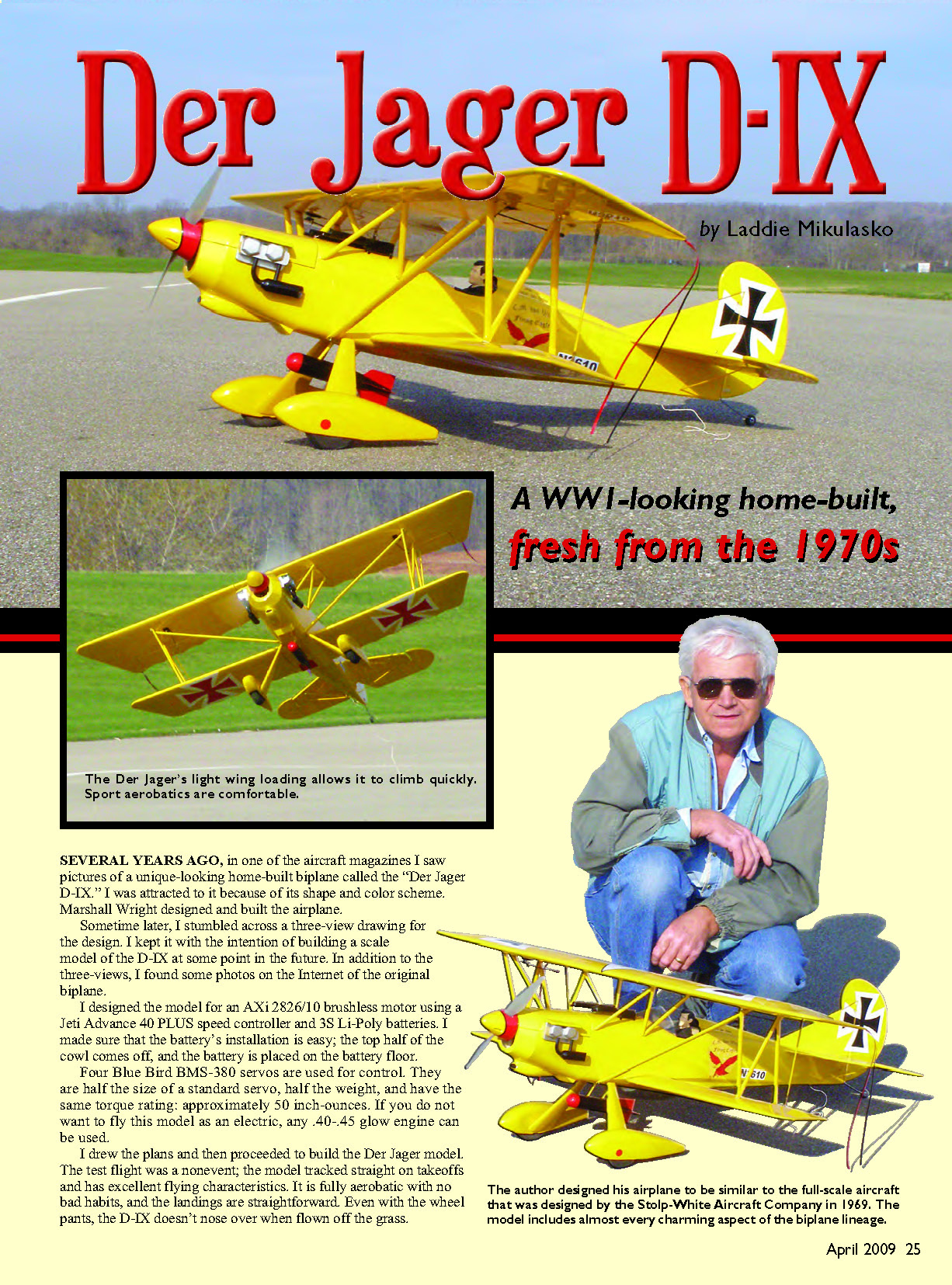
Der Jager D-IX
by Laddie Mikulasko
A WWI-looking home-built, fresh from the 1970s
Several years ago, in one of the aircraft magazines I saw pictures of a unique-looking home-built biplane called the "Der Jager D-IX." I was attracted to it because of its shape and color scheme. Marshall Wright designed and built the airplane.
Sometime later, I stumbled across a three-view drawing for the design and kept it with the intention of building a scale model of the D-IX. In addition to the three-views, I found photos on the Internet of the original biplane.
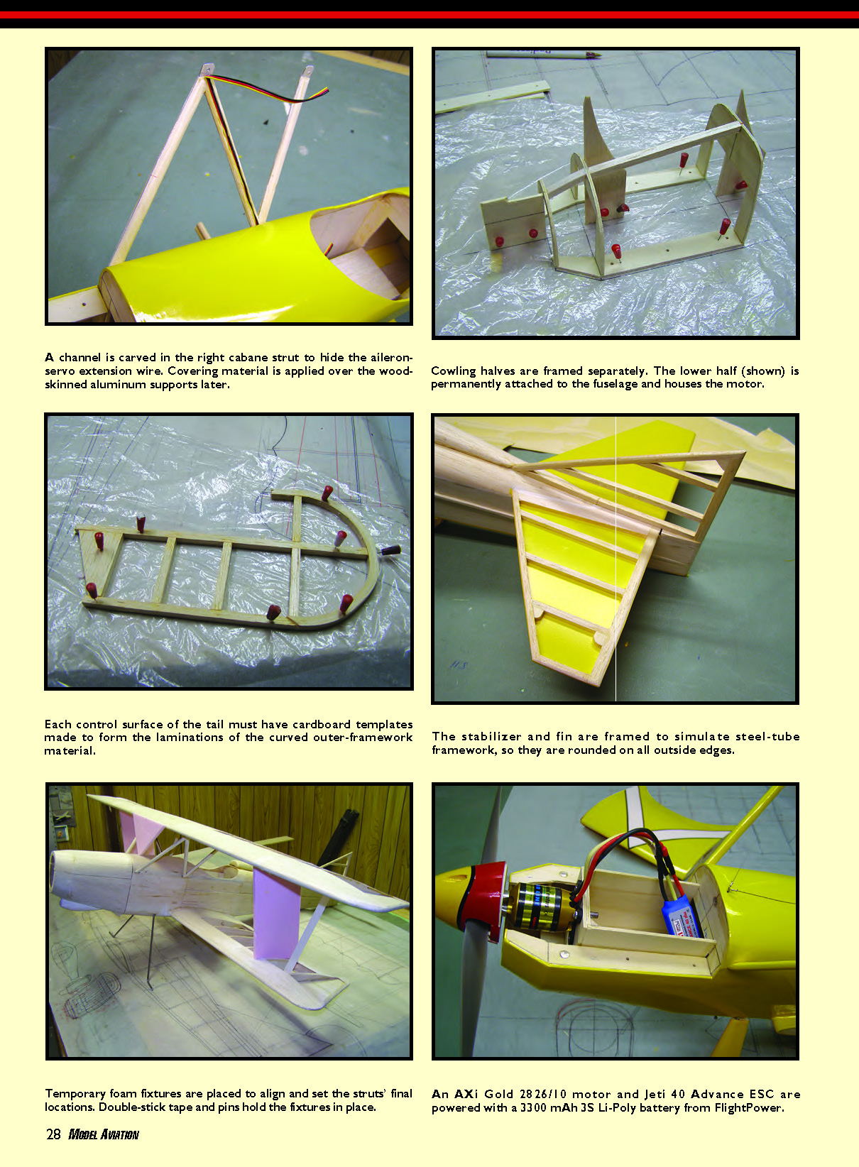
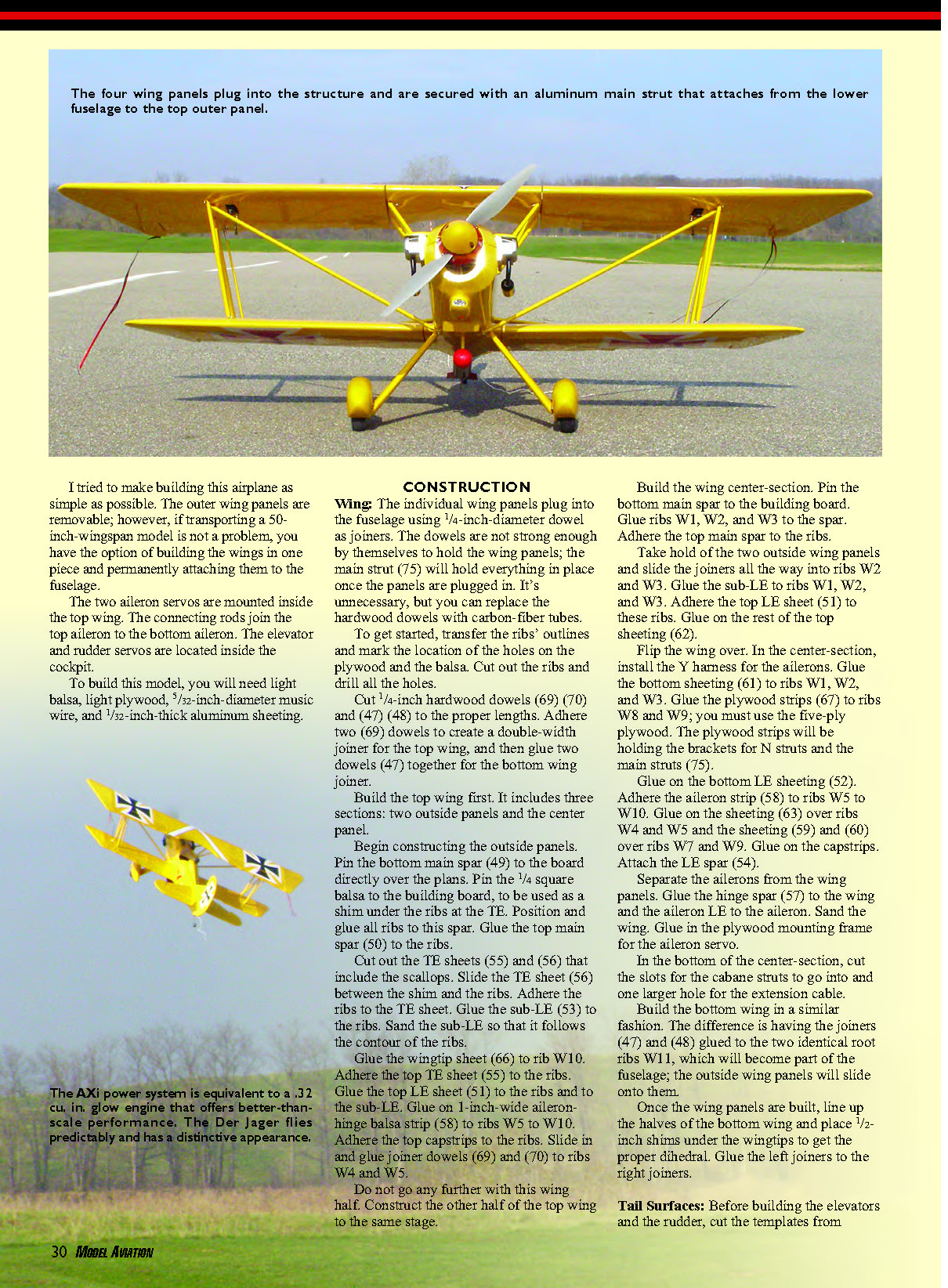
I designed the model for an AXi 2826/10 brushless motor using a Jeti Advance 40 PLUS speed controller and 3S Li-Poly batteries. The battery installation is easy: the top half of the cowl comes off and the battery is placed on the battery floor.
Four Blue Bird BMS-380 mini servos are used for control. They are half the size and weight of a standard servo yet have similar torque (approximately 50 in-oz). If you do not want to fly this model as an electric, any .40–.45 glow engine can be used.
I drew the plans and proceeded to build the Der Jager model. The test flight was a nonevent: the model tracked straight on takeoff and has excellent flying characteristics. It is fully aerobatic with no bad habits, and the landings are straightforward. Even with the wheel pants, the D-IX doesn’t nose over when flown off grass.
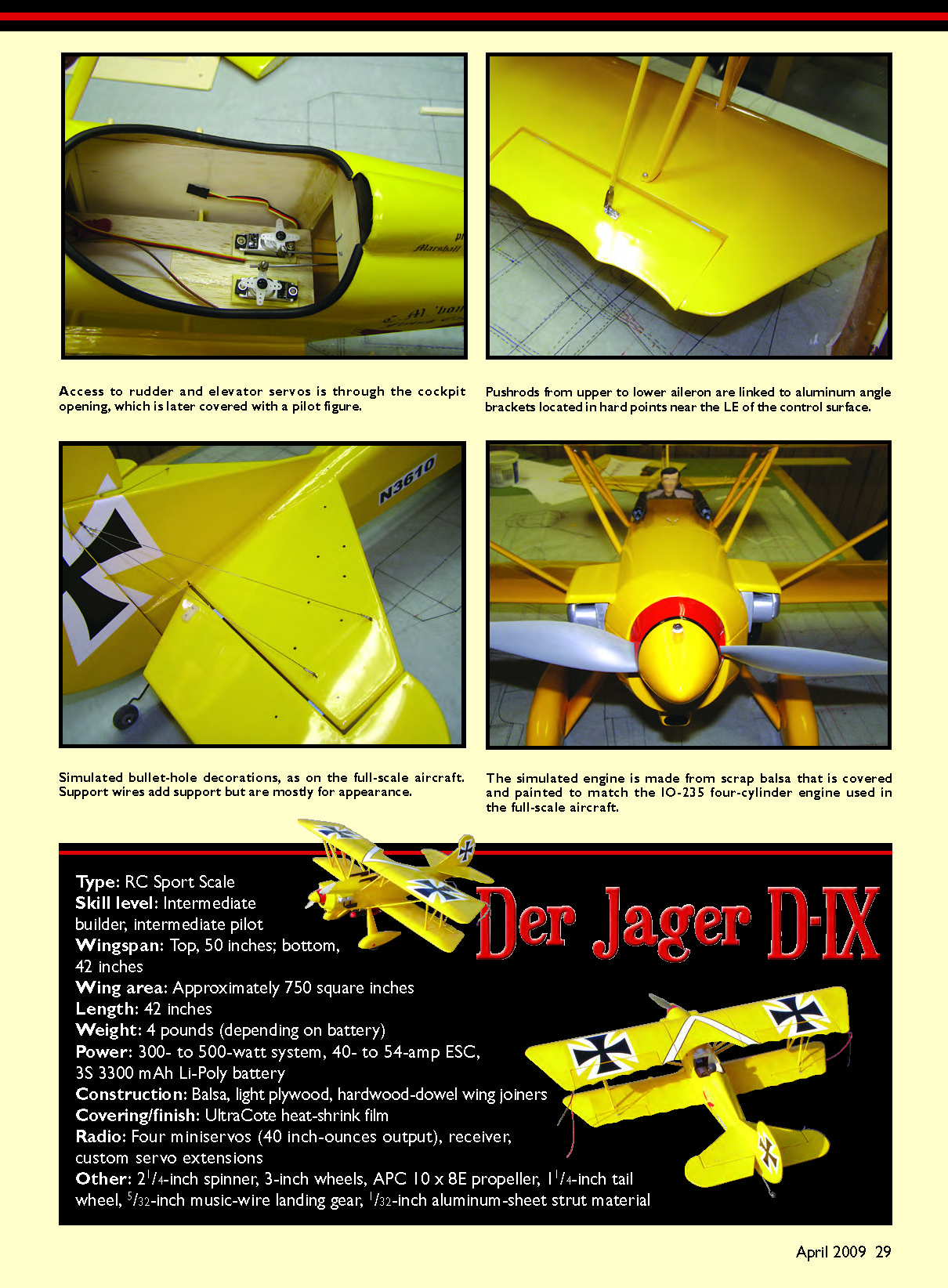
Type: RC Sport Scale Skill level: Intermediate builder, intermediate pilot
Specifications
- Wingspan: top 50 in; bottom 42 in
- Wing area: approximately 750 sq in
- Length: 42 in
- Weight: about 4 lb (depending on battery)
- Power: 300–500 W system, 40–54 A ESC, 3S 3300 mAh Li-Poly battery
- Construction: balsa, light plywood, hardwood-dowel wing joiners
- Covering/finish: UltraCote heat-shrink film
- Radio: four mini servos (≈40 in-oz), receiver, custom servo extensions
- Other: 2 1/4 in spinner, 3 in wheels, APC 10×8E propeller, 1 1/4 in tail wheel, 5/32 in music-wire landing gear, 1/32 in aluminum-sheet strut material
Materials required: light balsa, light plywood, 1/32‑in-diameter music wire, 1/32‑in-thick aluminum sheeting.
I tried to make building this airplane as simple as possible. The outer wing panels are removable; however, if transporting a 50‑inch wingspan model is not a problem, you may build the wings in one piece and permanently attach them to the fuselage.
The two aileron servos are mounted inside the top wing; connecting rods join the top aileron to the bottom aileron. The elevator and rudder servos are located inside the cockpit.
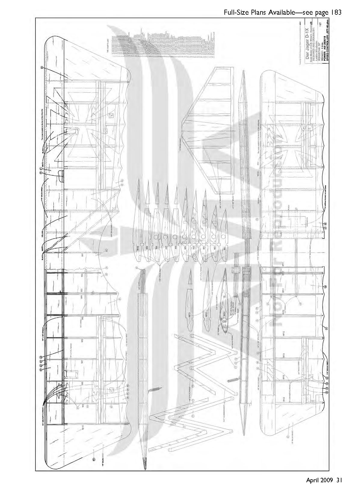
CONSTRUCTION
Wing
- The individual wing panels plug into the fuselage using 1/4‑in-diameter dowels as joiners. The dowels are not strong enough by themselves to hold the wing panels; the main strut (75) will hold everything in place once the panels are plugged in. You may substitute carbon-fiber tubes for the hardwood dowels if desired.
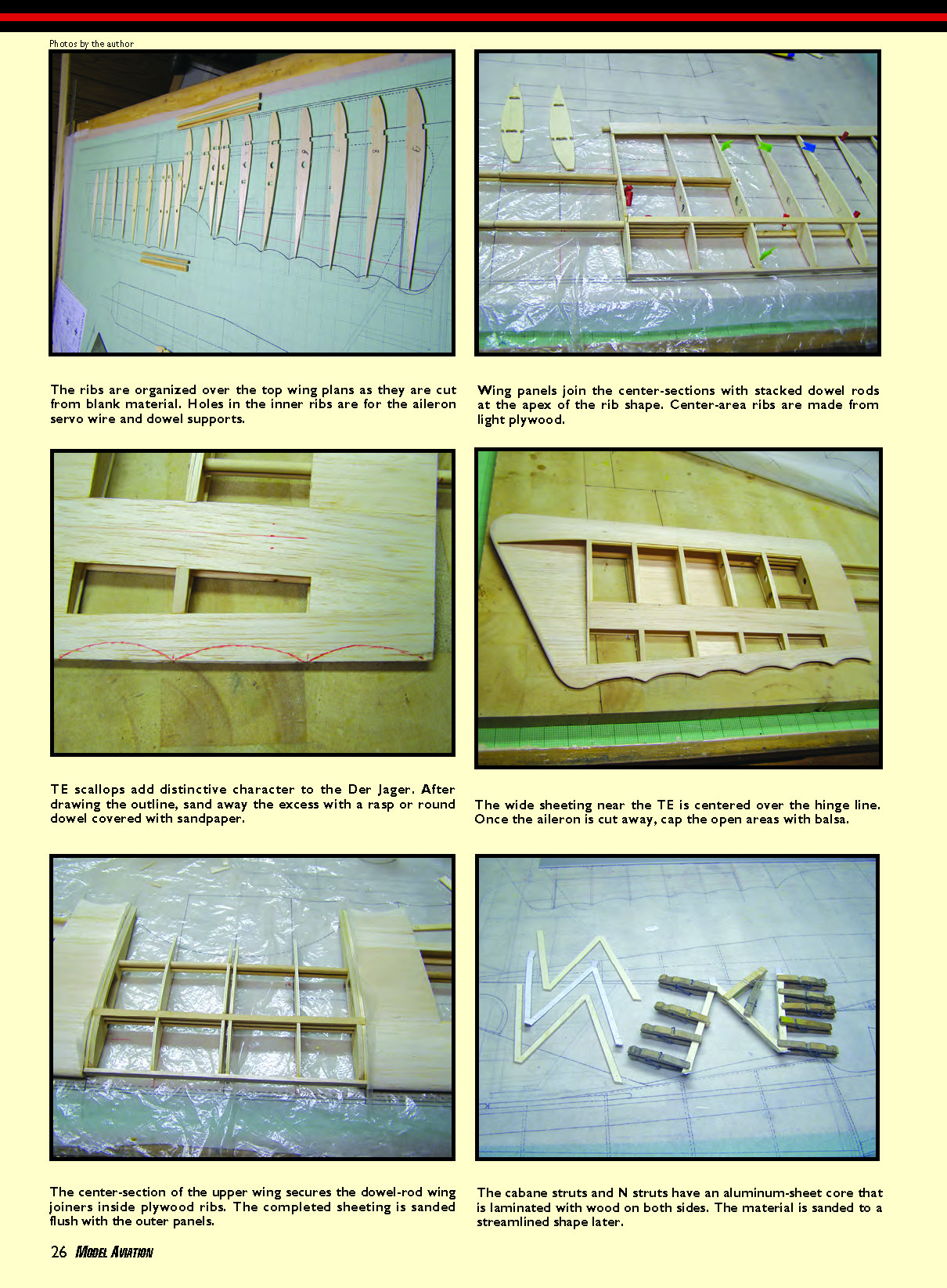
- Transfer the ribs' outlines and mark hole locations on the plywood and balsa. Cut out ribs and drill all holes.
- Cut 1/4‑in hardwood dowels (parts 69, 70, 47, 48) to length. Glue two 69 dowels together for a double-width top wing joiner; glue two 47 dowels together for the bottom wing joiner.
- Build the top wing first (three sections: two outside panels and the center panel).
Outside panels:
- Pin the bottom main spar (49) to the board over the plans. Pin 1/4‑square balsa as a shim under the ribs at the TE.
- Position and glue all ribs to the bottom spar. Glue the top main spar (50) to the ribs.
- Cut TE sheets (55) and (56) including scallops. Slide TE sheet (56) between the shim and ribs and glue ribs to it.
- Glue sub-LE (53) to ribs and sand to match rib contour.
- Glue wingtip sheet (66) to rib W10. Glue top LE sheet (51) to ribs and sub-LE.
- Glue 1‑in-wide aileron-hinge balsa strip (58) to ribs W5–W10. Glue top capstrips.
- Slide and glue joiner dowels (69) and (70) into ribs W4 and W5.
Do not proceed further with this wing half; build the other half to the same stage.
Center-section:
- Pin bottom main spar and glue ribs W1–W3, then glue top main spar.
- Slide the two outside wing panels so joiners fully seat into ribs W2 and W3.
- Glue sub-LE to ribs W1–W3 and glue top LE sheet (51). Glue the remaining top sheeting (62).
- Flip wing over; install Y-harness for the ailerons in the center-section.
- Glue bottom sheeting (61) to ribs W1–W3.
- Glue five-ply plywood strips (67) to ribs W8 and W9 — these hold brackets for N struts and main strut (75).
- Glue bottom LE sheeting (52), aileron strip (58) to ribs W5–W10, sheeting (63) over ribs W4–W5, sheeting (59) and (60) over ribs W7 and W9. Glue on capstrips and attach LE spar (54).
- Separate ailerons from wing panels. Glue hinge spar (57) to the wing and the aileron LE to the aileron. Sand wing and glue in plywood mounting frame for aileron servo.
- In the bottom of the center-section, cut slots for cabane struts and a larger hole for the extension cable.
Bottom wing:
- Build similarly. The difference: joiners (47) and (48) are glued to the two identical root ribs W11, which become part of the fuselage; outside panels slide into them.
- Once panels are built, align bottom halves, place 1/2‑in shims under wingtips to set proper dihedral, and glue left joiners to right joiners.
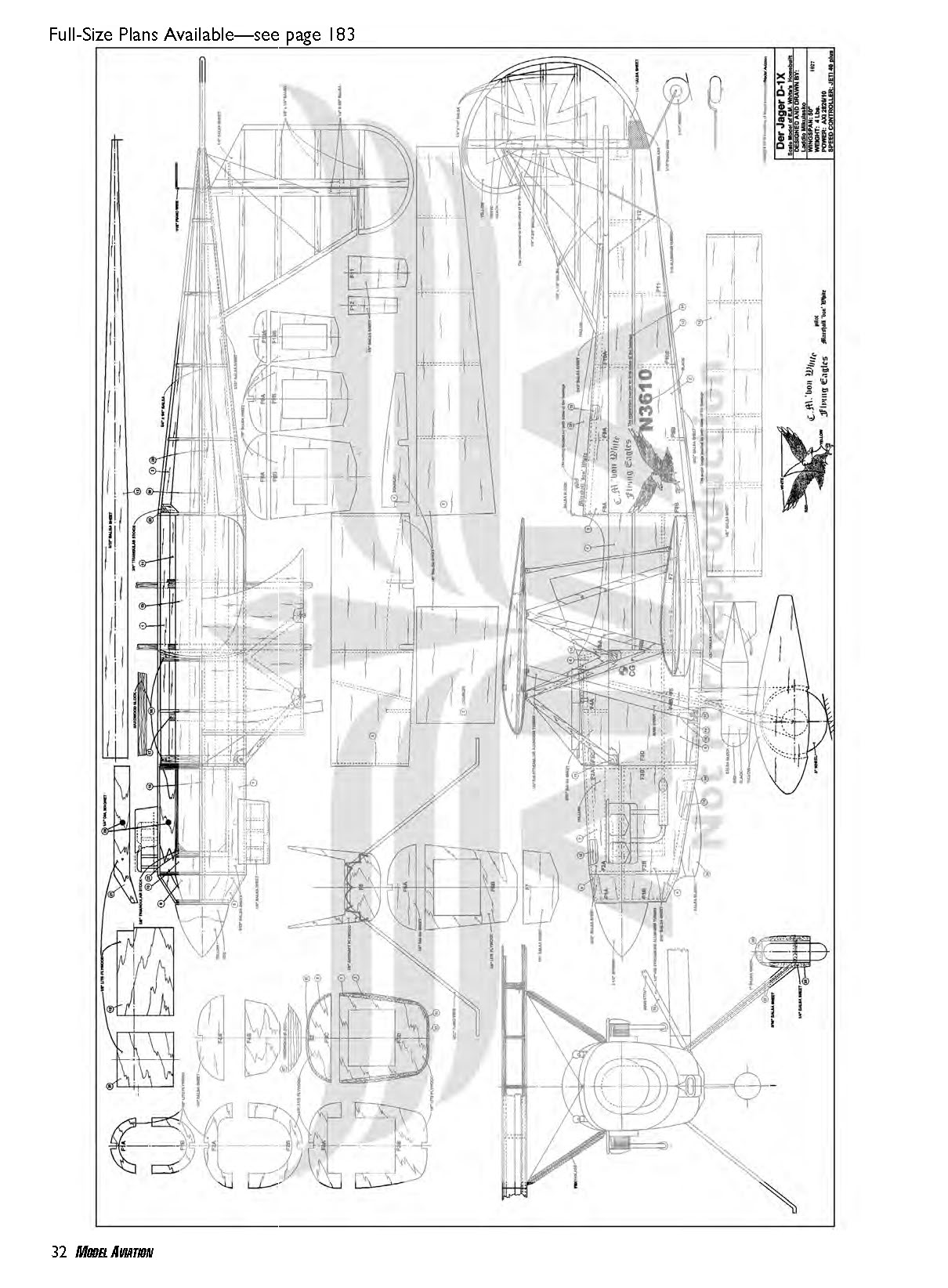
Tail Surfaces
- Cut templates from plans and transfer outlines to balsa.
- The stabilizer and fin are framed to simulate steel-tube construction. Stabilizer ribs are from 1/16‑in balsa; 1/8‑in balsa sheeting is used for the leading edge.
- Build elevator halves directly over the plans; trim, hinge together, and install control horn. Build the rudder similarly.
- After sanding, sheet the forward portions with 1/32‑in plywood and sand to shape.
- Build stabilizer and fin frames and sand all surfaces.
- Bend 1/16‑in-diameter piano wire to form the tail-wheel strut; insert into balsa in the rudder and glue with thin cyanoacrylate. Wrap the whole sheet with fiberglass and saturate with thin cyanoacrylate.
Cabane and Wing N Struts
- Cut four identical cabane struts (72) and four N struts (74) from 1/8‑in light plywood.
- Cut two cabane struts (71) and two N struts (73) from 1/32‑in aluminum sheet. Drill 1/16‑in holes in N struts per drawing.
- Sand aluminum surfaces. Use cyanoacrylate or GOOP-type adhesive to laminate plywood pieces to both sides of the aluminum struts. Sand edges to streamline shape.
- Cut a slot in one front cabane strut to insert and glue the aileron-servo extension cable.
- Wrap all struts with fiberglass and saturate with thin cyanoacrylate. Sand lightly and bend exposed aluminum ends per drawing.
Fuselage
The fuselage is built inside-down in three sections: the cowl, the center-section, and the tail section.
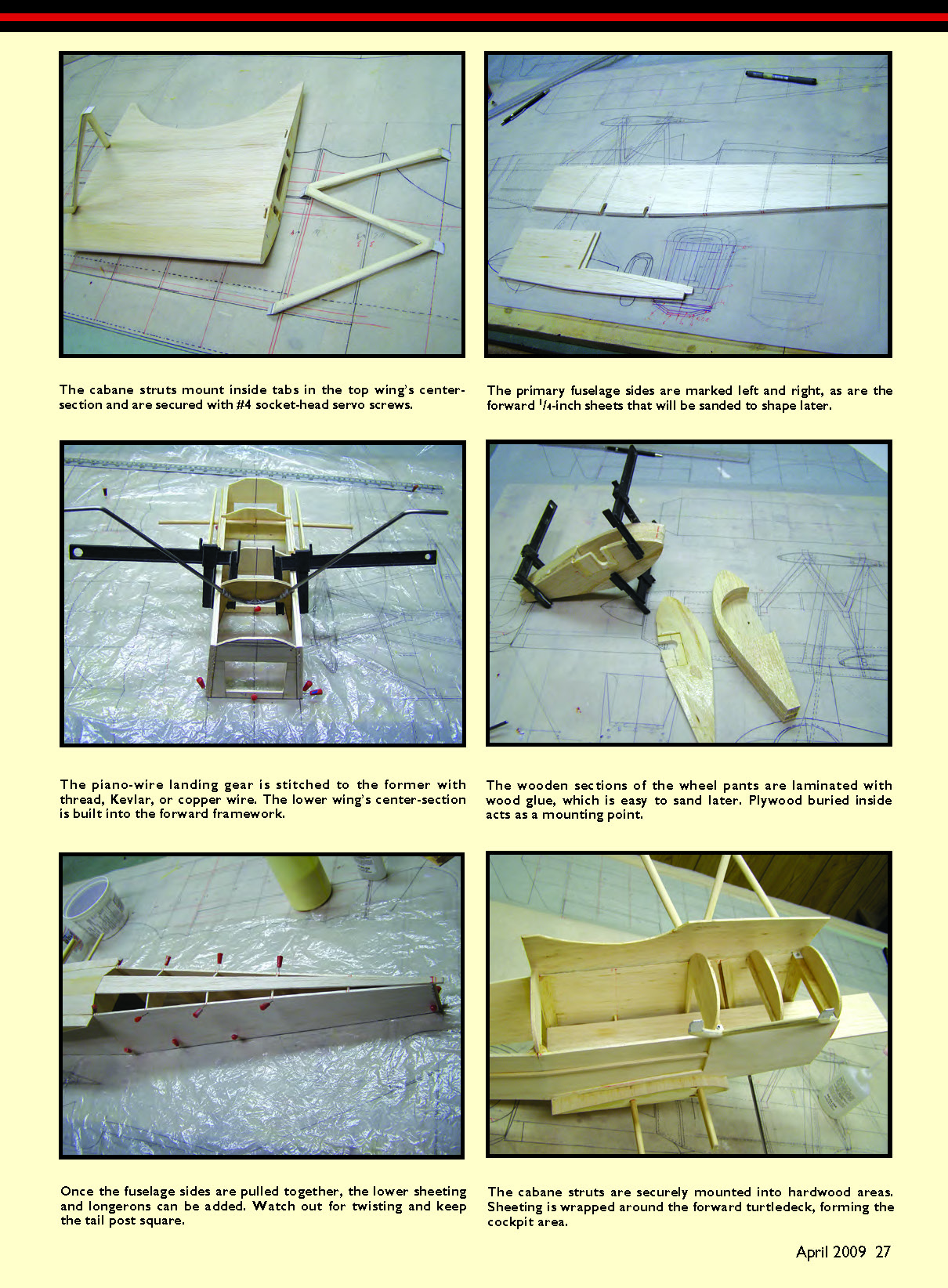
- Cut out as many parts as possible. Cut and bend 5/32‑in-diameter piano wire to form main landing-gear legs and attach them to former F5 with thread (canvas thread, Kevlar, or copper wire).
- Glue hardwood block (17) to former F4B; glue hardwood blocks (18) to formers F3D and F6B. Pin formers F3D, F5, F6B, and F8B to the building board. Pin and glue fuselage sides (1) to these formers.
- Insert and glue battery floor (13) and formers F4B and F7.
- Pin formers F9B, F10B, F11, and F12 to the building board. Glue rear fuselage sides (2) to these formers and to fuselage side (1). Glue 3/8‑in triangle stock between fuselage side (2) and former F8B.
- Glue balsa doublers (3) between formers F3D and F6B on the outside of the fuselage. Between F6B and F8B, glue doublers (4) to the fuselage sides.
- Glue the bottom wing to the fuselage: slide joiners (47) and (48) into slots in fuselage sides (1). Check alignment and glue joiners to formers F6B and F7.
- Glue balsa strip (12) to the bottom of all formers. Complete sheeting of the bottom between formers F3B and F8B.
- Turn fuselage right-side up. Glue firewall (20) and firewall support sides (19) to battery floor (13) and former F3D.
Cowl:
- The cowl is built top and bottom. Cut four plywood pieces (21). Drill 1/4‑in hole for magnets and 1/16‑in hole for guide pins.
- Pin two plywood pieces (21) to the board, pin and glue formers F1B, F2B, and F3B to them. Insert and glue 1/4‑in square balsa into these formers. Glue sheeting (9) and (10).
- Remove bottom cowl from the board and glue scoop (24) to it. The bottom cowl can be glued to former F3D.
- Build removable top of cowl the same way but do not glue it to anything. Glue magnets and guide pins into plywood pieces (21).
Cabane and wing installation:
- Mount cabane to hardwood blocks (18) using self-tapping screws. Insert cabane top tabs into slots in the bottom of the top wing center-section. Line up holes on cabane struts with holes in W3 ribs and attach cabane to W3 ribs with self-tapping screws.
- Feed the plug from the aileron extension into the cavity between ribs W2 and W3.
- Plug in all wing panels and check alignment; adjust if necessary. Install wing N struts and hold them to the wings with self-tapping screws.
Main strut (75):
- Cut 1/2‑in K&S streamlined aluminum tube to length. Flatten ends, drill 3/32‑in holes at each end, and bend ends so the flat end sits flush with plywood (67) behind the top wing main spar. The other end follows the contour of hardwood block (17) in the fuselage. Drill holes in the hardwood block and plywood for self-tapping screws.
Final fuselage work:
- Remove wings from the fuselage, including center-section. Install servo extension for top aileron in the top wing.
- Glue stabilizer to the fuselage. Install top fuselage formers and glue top sheeting (5) to front fuselage formers and sheeting (6) to rear formers.
- Cut out cockpit opening and glue on headrest (25). Glue longeron (14) to the side of the fuselage. Glue fin to the fuselage.
- Make wheel pants and streamline covers for main gear legs from the balsa materials shown on the plans.
- Carve a channel in the right cabane strut to hide the aileron-extension wire. Cover aluminum-supported areas with covering material later.
- Install radio gear and test-fit cowling and wheel pants. Balance model at recommended CG.
Finishing
- Use your preferred finishing method; UltraCote was used for this model.
- After covering, install hinges and servos. Mount a threaded connecting rod between top and bottom ailerons with a clevis at each end. Attach a small L-shaped aluminum bracket to the plywood plate on each aileron with self-tapping screws.
- Make a dummy engine from scrap balsa pieces and glue it to the top half of the cowl.
- After installing the radio and motor, remove the top half of the cowl and slide the motor battery onto the battery floor. Check CG and move the battery as needed. Mark battery location and use hook-and-loop fastener to secure it.
- Install servos and check controls:
- Elevator: 3/4 in up and down
- Rudder: 1 1/4 in left and right at the widest point
- Top ailerons: 1/2 in up and down at the widest point
You're finished with the construction. Have fun flying this unique-looking scale model.
Laddie Mikulasko [email protected]
Sources
- AXi 2826/10 motor, Jeti 40 Advance ESC: MS Composites, (317) 578-1955, www.mscompositesusa.com
- UltraCote covering: Hangar 9, (800) 338-4639, www.hangar-9.com
- 3200 mAh EVO LiTE V2 3S battery: FlightPower, (919) 741-6310, www.flightpowerusa.com
Transcribed from original scans by AI. Minor OCR errors may remain.

