
Determining Static Thrust
by Donald W. Brooks
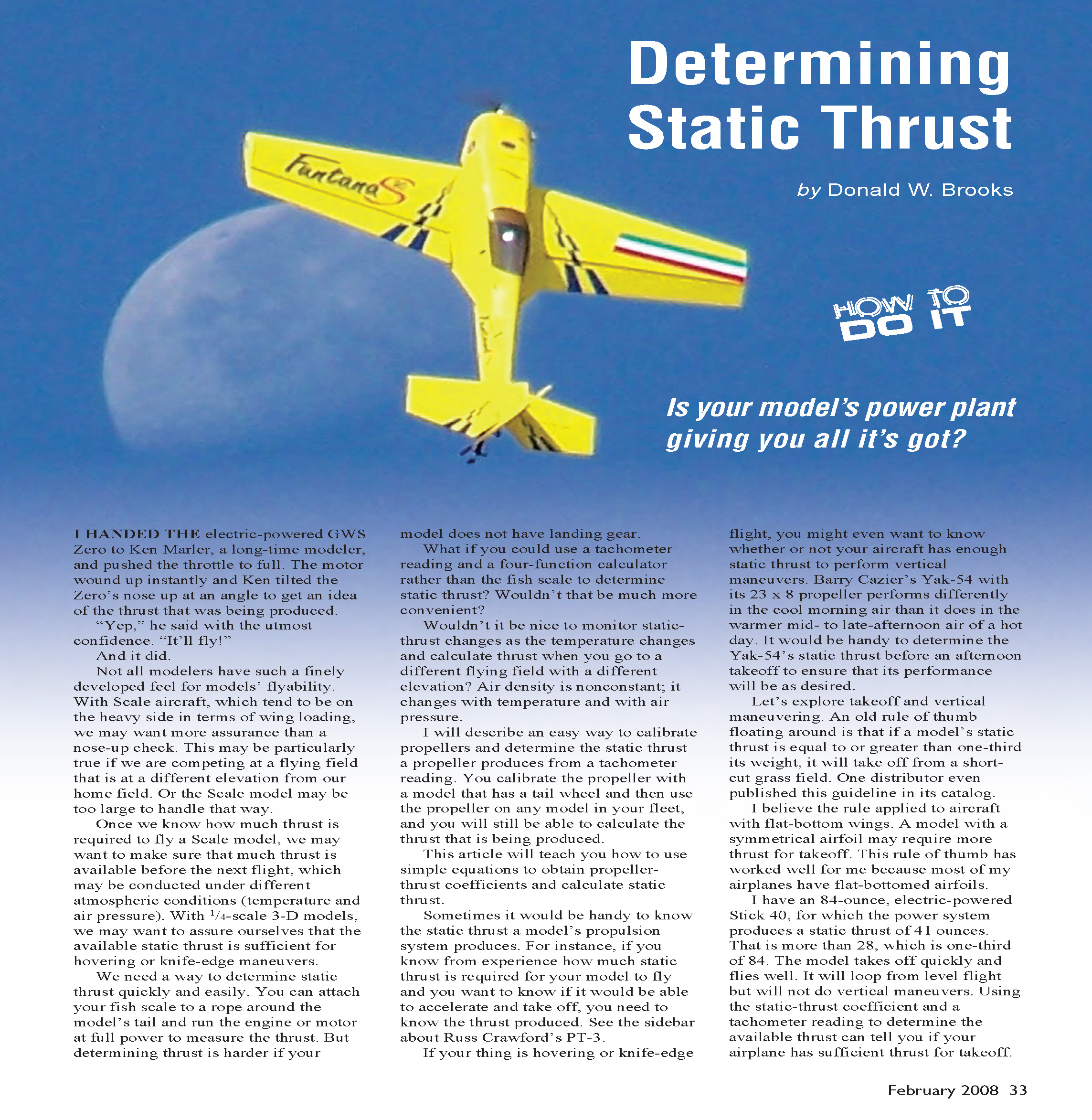
I handed the electric-powered GWS Zero to Ken Marler, a long-time modeler, and pushed the throttle to full. The motor wound up instantly and Ken tilted the Zero’s nose up to get an idea of the thrust that was being produced. “Yep,” he said with the utmost confidence. “It’ll fly!”
And it did.
Not all modelers have such a finely developed feel for a model’s flyability. With scale aircraft, which tend to be on the heavy side in terms of wing loading, we may want more assurance than a nose-up check. This may be particularly true if we are competing at a flying field that is at a different elevation from our home field, or when the scale model is too large to handle that way.
Once we know how much thrust is required to fly a scale model, we may want to make sure that much thrust is available before the next flight, which may be conducted under different atmospheric conditions (temperature and air pressure). With 1/4-scale 3-D models, we may want to assure ourselves that the available static thrust is sufficient for hovering or knife-edge maneuvers.
You can attach a fish scale to a rope around the model’s tail and run the engine or motor at full power to measure the thrust. But determining thrust is harder if your model does not have landing gear.
What if you could use a tachometer reading and a four-function calculator rather than the fish scale to determine static thrust? Wouldn’t that be much more convenient? Wouldn’t it be nice to monitor static-thrust changes as the temperature changes and calculate thrust when you go to a different flying field with a different elevation? Air density is nonconstant; it changes with temperature and with air pressure.
I will describe an easy way to calibrate propellers and determine the static thrust a propeller produces from a tachometer reading. You calibrate the propeller with a model that has a tail wheel and then use the propeller on any model in your fleet; you will still be able to calculate the thrust that is being produced.
This article will teach you how to use simple equations to obtain propeller-thrust coefficients and calculate static thrust.
Sometimes it is handy to know the static thrust a model’s propulsion system produces. For instance, if you know from experience how much static thrust is required for your model to fly and you want to know if it will be able to accelerate and take off, you need to know the thrust produced. If your thing is hovering or knife-edge flight, you might even want to know whether your aircraft has enough static thrust to perform vertical maneuvers.
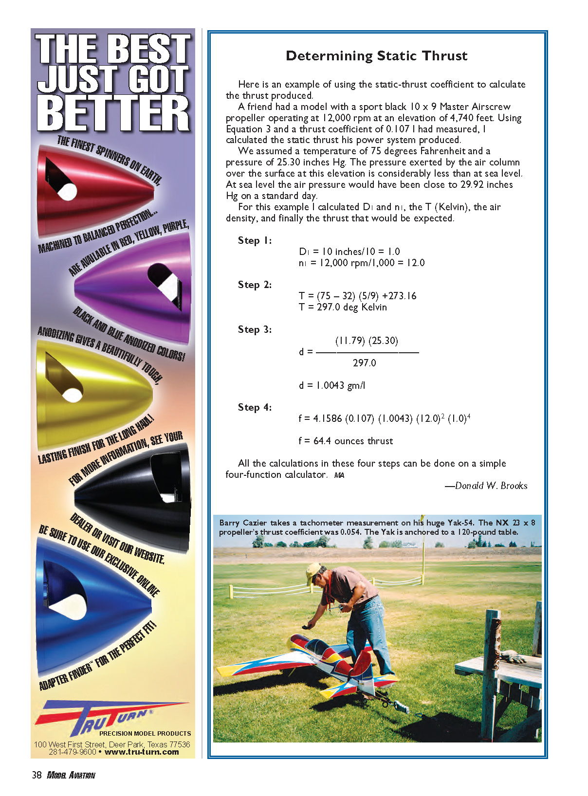
Barry Cazier’s Yak-54 with its 23 × 8 propeller performs differently in the cool morning air than it does in the warmer mid- to late-afternoon air of a hot day. It would be handy to determine the Yak-54’s static thrust before an afternoon takeoff to ensure that its performance will be as desired.
Let’s explore takeoff and vertical maneuvering. An old rule of thumb is that if a model’s static thrust is equal to or greater than one-third of its weight, it will take off from a short-cut grass field. I believe the rule applied to aircraft with flat-bottom wings; a model with a symmetrical airfoil may require more thrust for takeoff. This rule of thumb has worked well for me because most of my airplanes have flat-bottomed airfoils.
I have an 84-ounce, electric-powered Stick 40, for which the power system produces a static thrust of 41 ounces. That is more than 28, which is one-third of 84. The model takes off quickly and flies well. It will loop from level flight but will not do vertical maneuvers. Using the static-thrust coefficient and a tachometer reading to determine the available thrust can tell you if your airplane has sufficient thrust for takeoff.
When powering a new model, one approach is to ensure that a certain number of watts per pound or horsepower per pound is available from the power system. I will not discuss that here. However, once you have selected the power system, you can use the propeller static-thrust coefficient and a tachometer reading to determine the thrust that is available from your model’s power system to ensure that the performance is adequate.
The ability to accelerate to flight speeds, hover a model, or fly knife-edge maneuvers depends on propeller thrust. An extremely powerful motor or engine that is poorly matched to a propeller may produce less-than-desired thrust.
The Yak-54 Barry Cazier flies can do vertical maneuvers. When we tested Barry’s power system with its NX 23 × 8 propeller, we determined the thrust coefficient to be 0.054. It produced 18 pounds of thrust to pull the 16.5-pound model vertically straight up. Once we had measured the static-thrust coefficient, Barry had the option of using that propeller-thrust coefficient and a tachometer reading to determine the available thrust.
Why Concern Yourself With Static Thrust?
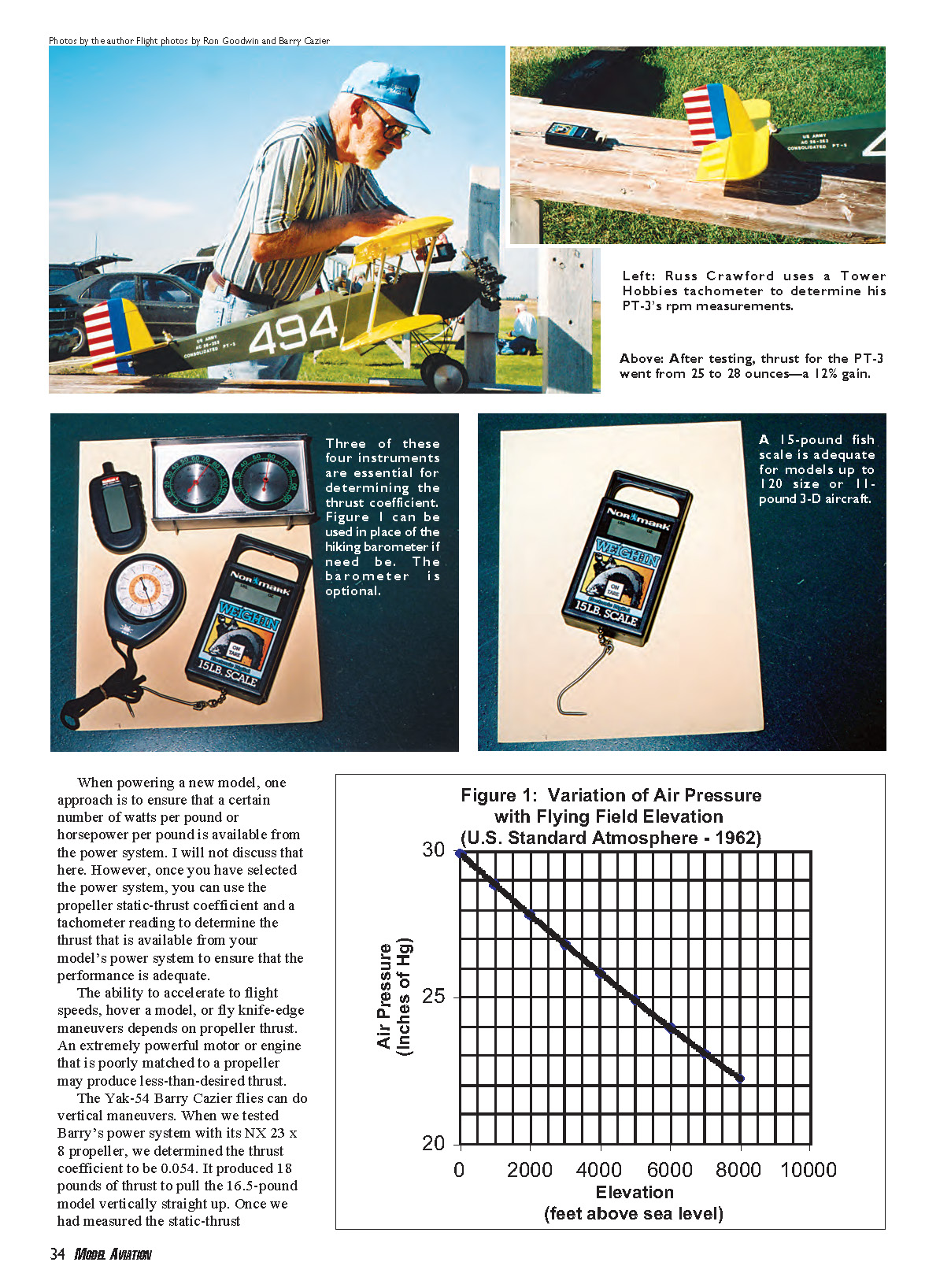
- Some scale models, such as Russ Crawford’s PT-3 shown in one of the photographs, are flying close to the limit for available thrust and wing loading. The model may perform well at a 4,700-foot elevation in the cool morning air but not be able to take off in the afternoon when the air is 30° warmer.
Being able to determine the thrust with a tachometer reading helps. Russ knows that if the PT-3’s static thrust drops below 25 ounces, he should ground the model and come back to fly another day.
- A scale model may fly well at sea level outside Pensacola, Florida. Take that same airplane to Reno, Nevada, to fly in a competition, and it may not fly or may not fly as well because of the lower air density caused by the reduction in air pressure. You may need to change the propeller to get improved thrust performance at the higher elevation.
If you know the thrust coefficient and have a tachometer, you can determine the available thrust and make necessary adjustments. Going from sea level to 4,500 feet along with a 30° increase in temperature may lower the air density by 20%. The decreased density affects wing lift, propeller thrust, and engine performance. The cumulative effects may give your model only 50% of the performance it had at sea level. If this is your situation, you need to know how much thrust you can depend on before the first flight at altitude.
- Barry Cazier’s Yak-54 performs differently in the morning than in the afternoon because of the temperature effect on air density. He likes to fly vertical maneuvers such as the Hover, the Waterfall, and knife-edge flight.
When we measured the thrust produced, it was approximately 18 pounds for a 16.5-pound aircraft. Barry had roughly a 9% excess of thrust. Once he has the thrust coefficient, he can tach the propeller at full throttle and determine quickly how much thrust he has to maneuver the model.
- A CL flier looks for consistent lap times for performing aerobatics with a model. Changing the flying-field elevation or air temperatures may necessitate a propeller change.
Lee Powell, a modeler in the local flying club, lives in Idaho Falls, Idaho (elevation 4,740 feet), and competes in Oregon (elevation roughly 400 feet). He flies with a shallower-pitched propeller on his CL model at the lower elevation to adjust the engine rpm, propeller thrust, and pitch speed for consistent lap times.
—Donald W. Brooks
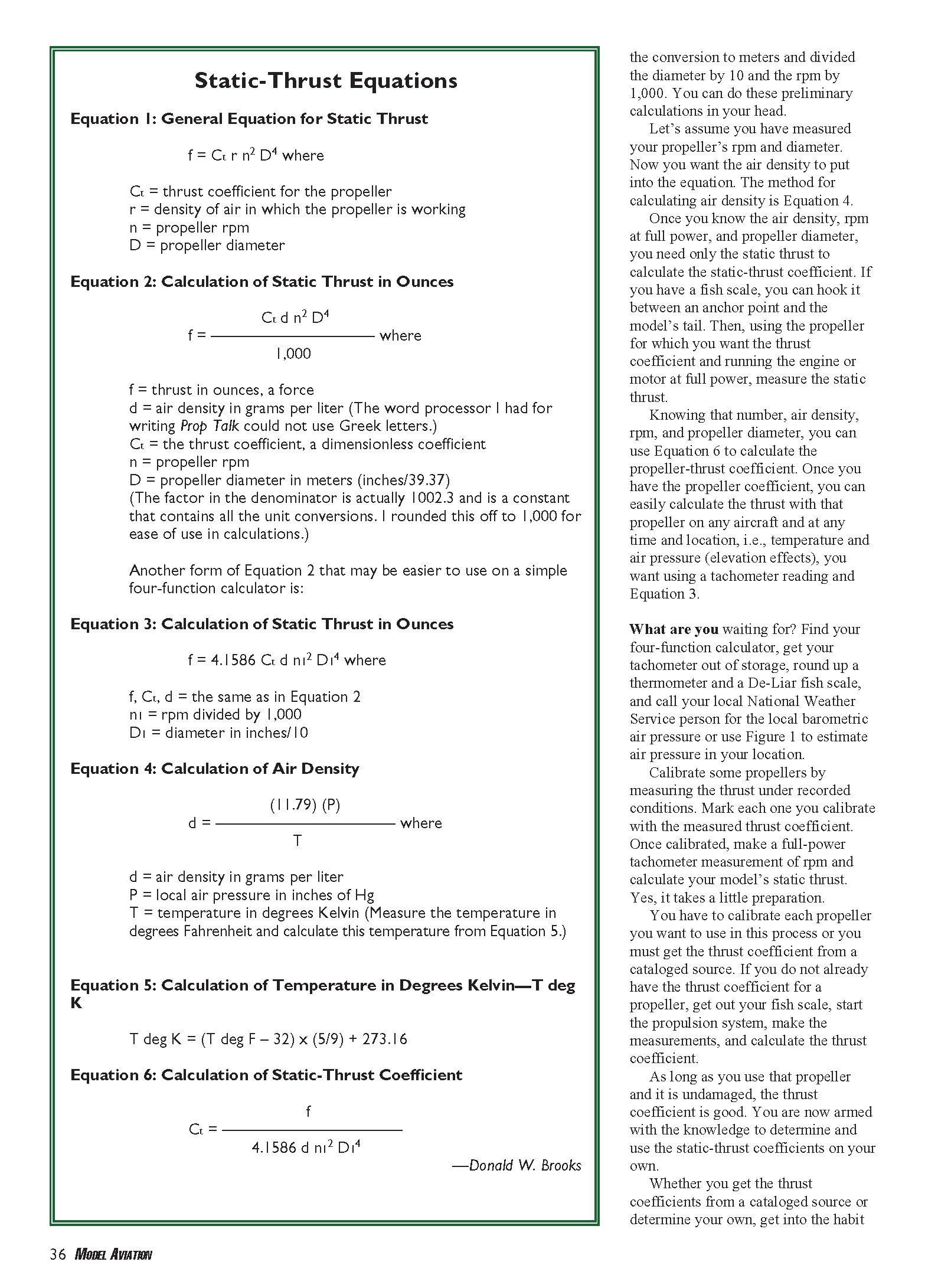
Static-Thrust Equations
Equation 1: General Equation for Static Thrust
f = Ct · r · n^2 · D^4
where
- Ct = thrust coefficient for the propeller
- r = density of air in which the propeller is working
- n = propeller rpm
- D = propeller diameter
Equation 2: Calculation of Static Thrust in Ounces
f = (Ct · d · n^2 · D^4) / 1,000
where
- f = thrust in ounces (force)
- d = air density in grams per liter (the word processor I used for writing Prop Talk could not use Greek letters)
- Ct = thrust coefficient (dimensionless)
- n = propeller rpm
- D = propeller diameter in meters (inches / 39.37)
(The factor in the denominator is actually 1002.3 and contains all the unit conversions. I rounded it to 1,000 for ease of use in calculations.)
Equation 3: Calculation of Static Thrust in Ounces (calculator-friendly form)
f = 4.1586 · Ct · d · n1^2 · D1^4
where
- f, Ct, d = same as in Equation 2
- n1 = rpm / 1,000
- D1 = diameter in inches / 10
Equation 4: Calculation of Air Density
d = (11.79 · P) / T
where
- d = air density in grams per liter
- P = local air pressure in inches of Hg
- T = temperature in degrees Kelvin
(Measure the temperature in degrees Fahrenheit and convert to Kelvin using Equation 5.)
Equation 5: Temperature in Degrees Kelvin
T (deg K) = (T (deg F) − 32) × (5/9) + 273.16
Equation 6: Calculation of Static-Thrust Coefficient
Ct = f / (4.1586 · d · n1^2 · D1^4)
I adapted Equation 1 into units that make it easy to use. For Equation 3 I divided the diameter by 10 and the rpm by 1,000 so you can do those preliminary calculations in your head.
To use these equations: measure the propeller’s rpm and diameter, calculate the air density, then either measure the static thrust (with a fish scale) to determine Ct, or use a known Ct from a cataloged source. Once you have Ct you can calculate the thrust for any rpm and air density using Equation 3.
Measuring Propeller Static-Thrust Coefficient
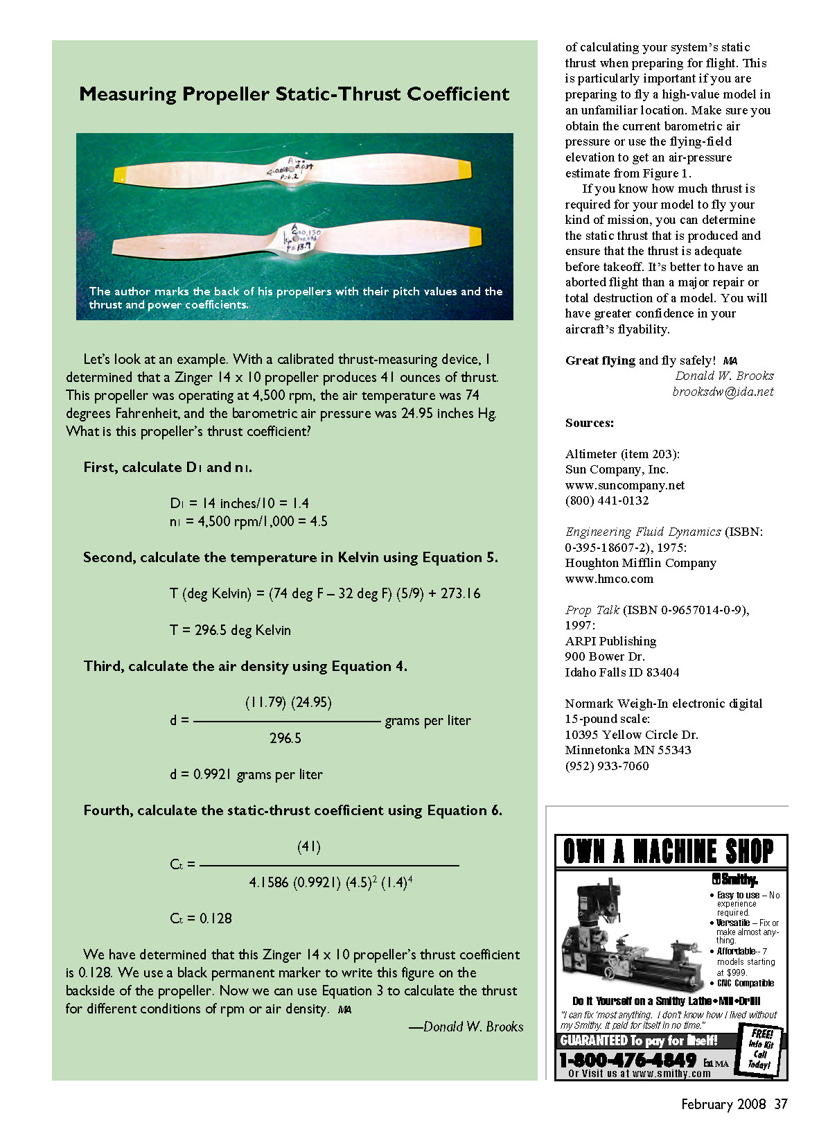
The author marks the back of propellers with their pitch values and the measured thrust and power coefficients.
Example: With a calibrated thrust-measuring device, I determined that a Zinger 14 × 10 propeller produces 41 ounces of thrust. This propeller was operating at 4,500 rpm, the air temperature was 74°F, and the barometric air pressure was 24.95 inches Hg. What is this propeller’s thrust coefficient?
Step 1: Calculate D1 and n1.
- D1 = 14 inches / 10 = 1.4
- n1 = 4,500 rpm / 1,000 = 4.5
Step 2: Calculate the temperature in Kelvin (Equation 5).
- T = (74 − 32) × (5/9) + 273.16 = 296.5 K
Step 3: Calculate the air density (Equation 4).
- d = (11.79 × 24.95) / 296.5 = 0.9921 g/L
Step 4: Calculate the static-thrust coefficient (Equation 6).
- Ct = 41 / [4.1586 × 0.9921 × (4.5)^2 × (1.4)^4] = 0.128
We have determined that this Zinger 14 × 10 propeller’s thrust coefficient is 0.128. We write this figure on the backside of the propeller with a black permanent marker. Now we can use Equation 3 to calculate the thrust for different conditions of rpm or air density.
—Donald W. Brooks
Determining Static Thrust (Example)
Here is an example of using the static-thrust coefficient to calculate the thrust produced.
A friend had a model with a sport black 10 × 9 Master Airscrew propeller operating at 12,000 rpm at an elevation of 4,740 feet. Using Equation 3 and a thrust coefficient of 0.107 I had measured, I calculated the static thrust his power system produced. We assumed a temperature of 75°F and a pressure of 25.30 inches Hg.
Step 1:
- D1 = 10 inches / 10 = 1.0
- n1 = 12,000 rpm / 1,000 = 12.0
Step 2: Temperature in Kelvin
- T = (75 − 32) × (5/9) + 273.16 = 297.0 K
Step 3: Air density (Equation 4)
- d = (11.79 × 25.30) / 297.0 = 1.0043 g/L
Step 4: Thrust (Equation 3)
- f = 4.1586 × 0.107 × 1.0043 × (12.0)^2 × (1.0)^4 = 64.4 ounces thrust
All the calculations in these four steps can be done on a simple four-function calculator.
—Donald W. Brooks
Practical Notes and Recommendations
- Calibrate each propeller you want to use in this process, or obtain the thrust coefficient from a cataloged source. If you do not already have the thrust coefficient for a propeller, use a fish scale to measure the static thrust under recorded conditions and calculate Ct.
- Once a propeller is calibrated and undamaged, its thrust coefficient is valid for future calculations.
- Always check current barometric air pressure or use the flying-field elevation to estimate air pressure when preparing for flight at an unfamiliar location.
- If you know how much thrust is required for your model to perform its mission, calculate the static thrust that will be produced under current conditions. It’s better to abort a flight than risk major damage to a model.
Great flying and fly safely!
Donald W. Brooks [email protected]
Sources:
- Altimeter (item 203): Sun Company, Inc., www.suncompany.net, (800) 441-0132
- Engineering Fluid Dynamics (ISBN: 0-395-18607-2), 1975: Houghton Mifflin Company, www.hmco.com
- Prop Talk (ISBN 0-9657014-0-9), 1997: ARPI Publishing, 900 Bower Dr., Idaho Falls, ID 83404
- Normark Weigh-In electronic digital 15-pound scale: 10395 Yellow Circle Dr., Minnetonka, MN 55343, (952) 933-7060
Transcribed from original scans by AI. Minor OCR errors may remain.

