
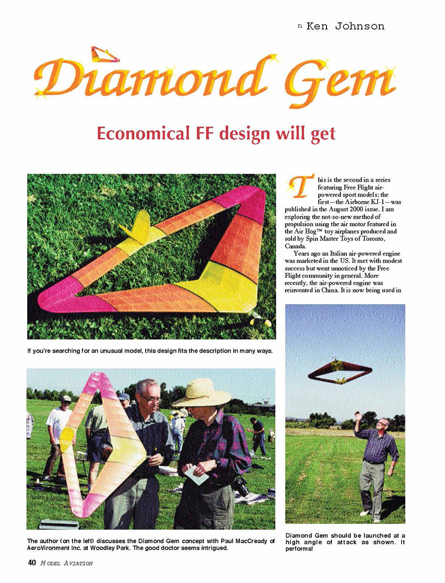
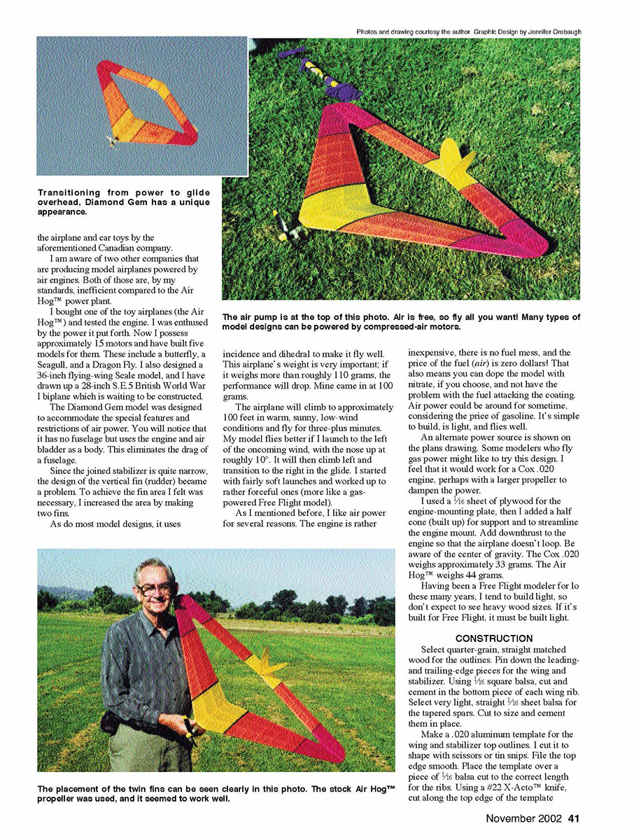
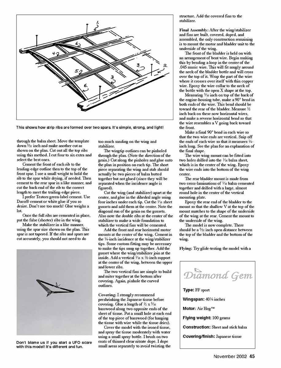
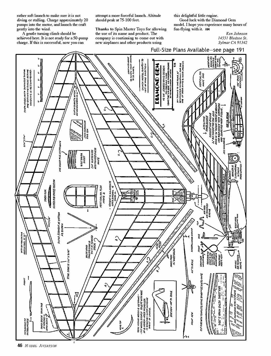
Diamond Gem
Ken Johnson
Economical FF design will get
This is the second in a series featuring Free Flight air-powered sport models; the first—the Airborne KJ-1—was published in the August 2000 issue. I am exploring the not-so-new method of propulsion using the air motor featured in the Air Hog™ toy airplanes produced and sold by Spin Master Toys of Toronto, Canada.
Years ago an Italian air-powered engine was marketed in the US. It met with modest success but went unnoticed by the Free Flight community in general. More recently, the air-powered engine was reinvented in China. It is now being used in the airplane and car toys by the aforementioned Canadian company.
I am aware of two other companies that are producing model airplanes powered by air engines. Both of those are, by my standards, inefficient compared to the Air Hog™ power plant.
I bought one of the toy airplanes (the Air Hog™) and tested the engine. I was enthused by the power it put forth. Now I possess approximately 15 motors and have built five models for them. These include a butterfly, a Seagull, and a Dragon Fly. I also designed a 36-inch flying-wing Scale model, and I have drawn up a 28-inch S.E.5 British World War I biplane which is waiting to be constructed.
The Diamond Gem model was designed to accommodate the special features and restrictions of air power. You will notice that it has no fuselage but uses the engine and air bladder as a body. This eliminates the drag of a fuselage.
Since the joined stabilizer is quite narrow, the design of the vertical fin (rudder) became a problem. To achieve the fin area I felt was necessary, I increased the area by making two fins.
As do most model designs, it uses incidence and dihedral to make it fly well. This airplane's weight is very important; if it weighs more than roughly 110 grams, the performance will drop. Mine came in at 100 grams.
The airplane will climb to approximately 100 feet in warm, sunny, low-wind conditions and fly for three-plus minutes. My model flies better if I launch to the left of the oncoming wind, with the nose up at roughly 10°. It will then climb left and transition to the right in the glide. I started with fairly soft launches and worked up to rather forceful ones (more like a gas-powered Free Flight model).
As mentioned before, I like air power for several reasons. The engine is rather inexpensive, there is no fuel mess, and the price of the fuel (air) is zero dollars! That also means you can dope the model with nitrate, if you choose, and not have the problem with the fuel attacking the coating. Air power could be around for sometime, considering the price of gasoline. It's simple to build, is light, and flies well.
An alternate power source is shown on the plans drawing. Some modelers who fly gas models might like to try this design. I feel that it would work for a Cox .020 engine, perhaps with a larger propeller to dampen the power.
I used a 1/16 sheet of plywood for the engine-mounting plate, then I added a half cone (built up) for support and to streamline the engine mount. Add downthrust to the engine so that the airplane doesn't loop. Be aware of the center of gravity. The Cox .020 weighs approximately 33 grams. The Air Hog™ weighs 44 grams.
Having been a Free Flight modeler for lo these many years, I tend to build light, so don't expect to see heavy wood sizes. If it's built for Free Flight, it must be built light.
CONSTRUCTION
Select quarter-grain, straight matched wood for the outlines. Pin down the leading- and trailing-edge pieces for the wing and stabilizer. Using 1/16 square balsa, cut and cement in the bottom piece of each wing rib. Select very light, straight 1/16 sheet balsa for the tapered spars. Cut to size and cement them in place.
Make a .020 aluminum template for the wing and stabilizer top outlines. I cut it to shape with scissors or tin snips. File the top edge smooth. Place the template over a piece of 1/16 balsa cut to the correct length for the ribs. Using a #22 X-Acto™ knife, cut along the top edge of the template through the balsa sheet. Move the template down 3/32 inch and make another cut as shown on the plan. Cut out all the top ribs using this method. I cut four to six extra and select the best ones.
Cement the front of each rib to the leading-edge outline then to the top of the front spar. I use a small weight to hold the rib to the spar while drying, if needed. Then cement to the rear spar in a like manner, and cut the back end of the rib to the correct length to meet the trailing-edge piece.
I prefer Testors green-label cement. Use Duco® cement or white glue if you so desire. Don't use too much! Glue weighs a lot.
Once the full ribs are cemented in place, put the false (shorter) ribs in the wing.
Make the stabilizer in a like manner, using the spar size shown on the plan. This spar is not tapered. If the ribs and spars are cut accurately, you should not need to do too much sanding on the wing and stabilizer.
The wingtip outlines can be pinholed through the plan. (Note the direction of the grain.) Cut along the pinholes and glue onto the plan in position on each tip. The short piece separating the wing and stab should actually be two pieces of balsa butted together not glued (since they will be separated when the incidence angle is figured).
Cut the wing (and stabilizer) apart at the center, and glue in the dihedral angle using four pins under each tip. Cut the 1/16 sheet gussets and add them at the center. Note the diagonal run of the grain on the gussets. Also note the double ribs at the center of the stabilizer to make a wide foundation to which the vertical fins will be cemented.
Add the front and rear horizontal motor mounts at the center of the wing. Cement in the 1/4-inch incidence at the wing/stabilizer tips. Some custom fitting may be necessary to make the tips snug up together. Add the gusset where the wing/stabilizer join at the inside. Add a vertical 1/16 x 1/8-inch support at the center of the wing, between the upper and lower ribs.
The two vertical fins are simple to build and miter together at the bottom after covering. Again, pinhole the curved outlines.
Covering: I strongly recommend preshrinking the Japanese tissue before covering. Glue a length of 1/2 x 3/16 basswood along two opposite ends of the sheet of tissue. Put a small hole at each end of the top piece of basswood (for hanging the tissue with wire while the tissue dries).
Cover the model with the ironed tissue, and spray the tissue moderately with water using a small spray bottle. I brush on two coats of thinned clear nitrate dope. I dope small areas separately to avoid twisting the structure. Add the covered fins to the stabilizer.
Final Assembly: After the wing/stabilizer and fins are built, covered, doped, and assembled, the only construction remaining is to mount the motor and bladder unit to the underside of the wing.
The front of the bladder is held on with an arrangement of bent wire. Begin making this by bending a loop in the center of the .045 music wire. This will fit snugly around the neck of the bladder bottle and will cross over the top of it. Wrap the part of the wire where it crosses over itself with thin copper wire. Epoxy the wire collar to the neck of the bottle with the open X shape at the top.
Measuring 3/16 inch on top of the back of the engine-housing tube, make a 90° bend in both ends of the wire. This bend should be toward the rear of the bladder. Measure 1/2 inch back on these now horizontal wires, and make a reverse horizontal bend so that the wire resembles a V going back toward the front.
Make a final 90° bend in each wire so that the two wire ends are vertical. Snip off the ends of each wire so that it measures 1/4-inch long. See the plan for an explanation of the final shape.
The wire wing mount can be fitted into two holes drilled into the 1/16 balsa sheet, which is in the center of the wing. Epoxy the wire ends into the bottom of the wing center.
The rear bladder mount is made from two cross-laminations of 1/16 balsa cemented together and drilled with a large, almost round hole in the center of the vertical mounting plate.
Epoxy the rear end of the bladder to the mount so that the shallow V at the top of the mount matches the shape of the underside of the wing at the rear. Cement the mount to the underside of the wing.
The model is now complete. There should be a 5/32 inch open distance between the top of the bladder and the bottom of the wing.
Flying: Try glide-testing the model with a
Diamond Gem
Type: FF sport
Wingspan: 40¾ inches
Motor: Air Hog™
Flying weight: 100 grams
Construction: Sheet and stick balsa
Covering/finish: Japanese tissue
Full-Size Plans Available—see page 191
Transcribed from original scans by AI. Minor OCR errors may remain.

