
Direct Servo Connection for CL Models
Fred Cronenwett
Today's Control Line (CL) models are a far cry from those of the 1950s and 1960s. They are larger, lighter, and have more features. Modern CL models can take advantage of commercially available retractable landing gear, fiberglass fuselages, and electric motors. In the past, retractable gear on a CL model required a fourth line and lots of pushrods; these mechanical systems are difficult to set up.
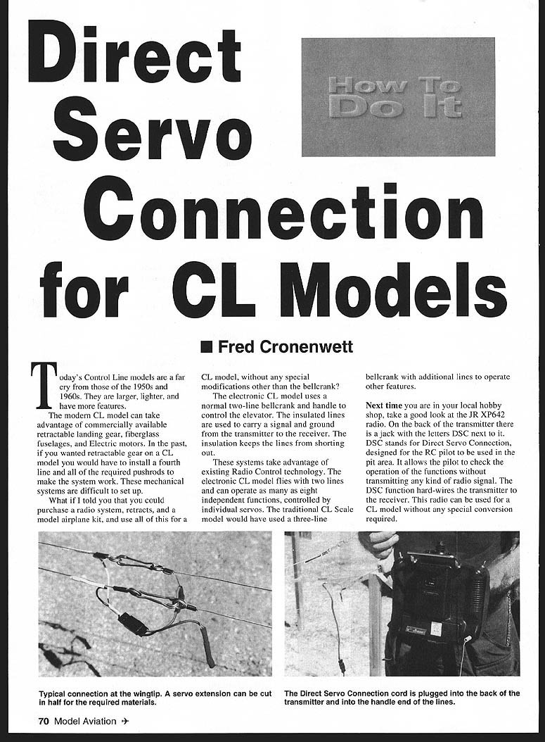
What if you could purchase a radio system, retracts, and a model kit and use them on a CL model with no special modifications other than the bellcrank? The electronic CL model uses a normal two-line bellcrank and handle to control the elevator while insulated flying lines carry signal and ground from the transmitter (TX) to the receiver (RX). The insulation keeps the lines from shorting when they touch.
These systems take advantage of existing radio-control technology. An electronic CL model flies with two lines and can operate as many as eight independent functions (servos). A traditional CL scale model would have used a three-line bellcrank with additional lines for other features. The electronic approach eliminates many pushrods, springs, and mechanical connections; servos can be placed next to the device they operate, with only short pushrods required.
Radio features and DSC setup
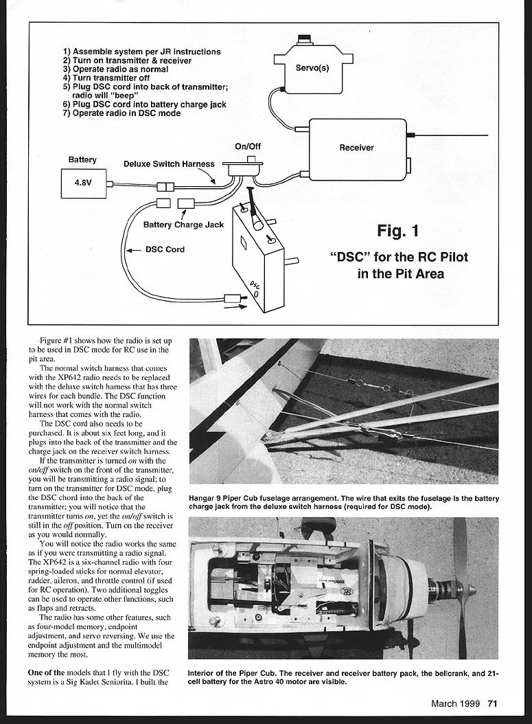
Next time you're in your hobby shop, look at the JR XP642 radio. On the back of the transmitter there is a jack marked DSC (Direct Servo Connection). DSC was designed to hard-wire the transmitter to the receiver so RC pilots can check functions in the pit area without transmitting RF. This same DSC function lets you use the radio for CL flight without special conversions.
Basic DSC setup:
- Assemble the system per JR instructions.
- Turn transmitter and receiver on.
- Operate the radio normally to confirm functions.
- Turn the transmitter off.
- Plug the DSC cord into the transmitter — the radio will beep and power up even though the front on/off switch remains off.
- Plug the other end of the DSC cord into the receiver switch harness charge jack.
- Operate the radio in DSC mode.
Important hardware notes:
- The normal switch harness that ships with the XP642 must be replaced with the deluxe switch harness; the deluxe harness has three wires per bundle and is required for DSC to function.
- The DSC cord (about six feet long) must be purchased separately. It plugs into the back of the transmitter and into the receiver switch harness charge jack.
- When the DSC cord is plugged in and the transmitter is in DSC mode, you will not be transmitting an RF signal. The radio will function as if transmitting, but it is hard-wired to the receiver.
The XP642 is a six-channel radio with four spring-loaded sticks (typically elevator, rudder, aileron, throttle in RC use) and two extra toggles for functions like flaps and retracts. Useful features include four-model memory, endpoint adjustment, and servo reversing.
Model example — Sig Kadet Seniorita build and servos
I fly a Sig Kadet Seniorita built per Sig's instructions but modified to be a taildragger with flaps and a changed nose section. The model uses six servos:
- Throttle (1)
- Rudder (1)
- Elevator (1)
- Camera shutter release (1)
- Flaps (2, one per wing panel)
I added an Ace Servo Master between the receiver and the flap servos to slow flap deployment. With a flap toggle, a normal servo moves very quickly and drops the flaps in less than a second, causing the nose to pitch up and trim to change abruptly. The Servo Master slows flap deployment to about five seconds, allowing the pilot to trim the elevator as the flaps come down. This looks more natural and adds realism for CL scale competition.
The Servo Master can also sequence landing-gear doors: one servo opens/closes the doors while another operates an air valve. Both servos can be sequenced from a single channel.
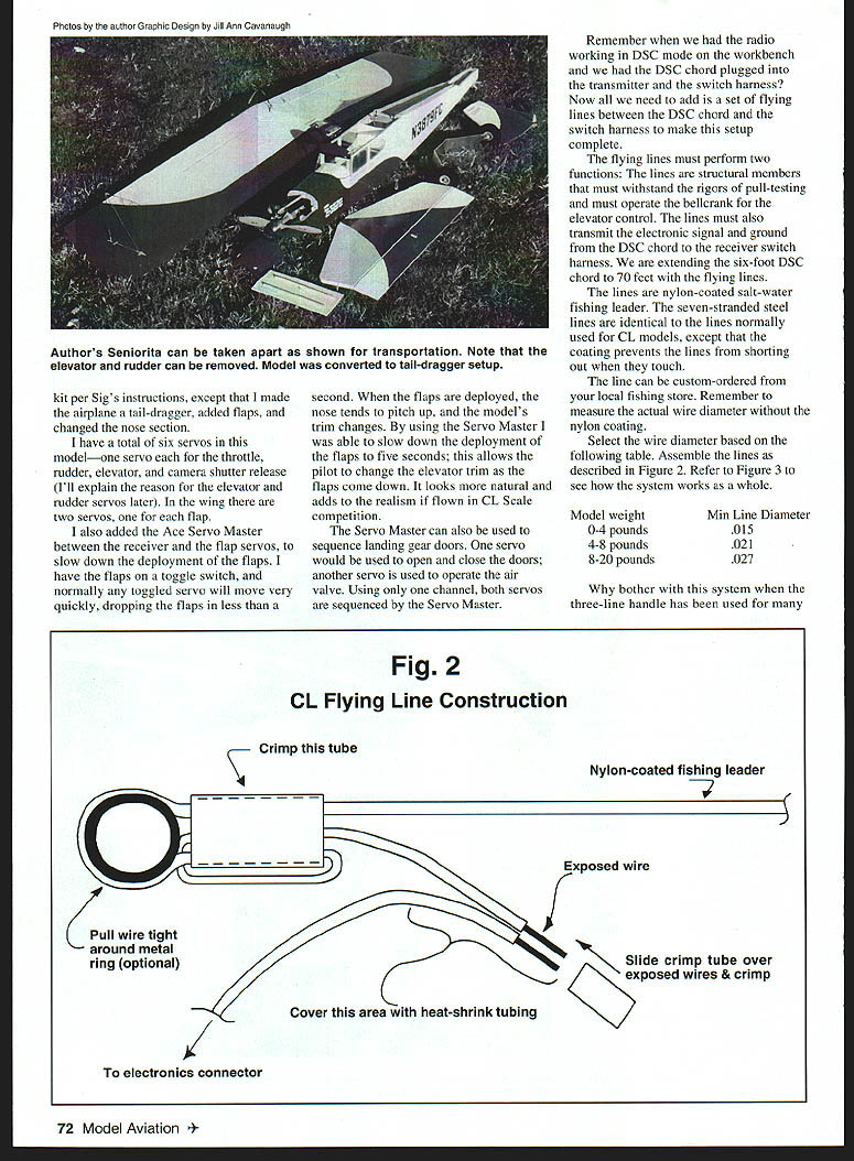
Flying lines — structure and signal
To use the DSC setup in flight you need flying lines between the DSC cord and the receiver switch harness. The flying lines must:
- Act as structural members (withstand pull-testing).
- Operate the bellcrank for elevator control.
- Transmit the electronic signal and ground from the DSC cord to the receiver.
In effect you are extending the six-foot DSC cord to about 70 feet using the flying lines. Use nylon-coated, salt-water fishing leader. The seven-stranded steel leaders are identical to lines normally used for CL models except for the nylon coating that prevents electrical shorts when lines touch.
Order the line from your local fishing store and measure the actual wire diameter without the nylon coating. Suggested line diameter by pull strength:
- 0–4 pounds: .015 in
- 4–8 pounds: .021 in
- 8–20 pounds: .027 in
Advantages over three-line systems
Ask yourself:
- How many functions can a three-line handle operate?
- Can the three-line handle make neutral-elevator adjustments easily?
- If you add flaps, retracts, and bomb drop, are you prepared to add more lines and the additional drag?
Electronically controlled CL eliminates pushrods and complex mechanical linkages. All functions (flaps, retracts, doors, valves) can be servo-operated and controlled over two insulated lines, reducing drag and simplifying setup. Endpoint adjustment and servo reversing on the radio make installation and trimming fast at the field.
Endpoint adjustment, servo reversing, and notes
- Servo reversing lets you flip servo rotation direction to match any orientation.
- Endpoint adjustment limits servo travel and is useful for fine-tuning flaps, air valves, and retracts. You can limit throw from 0–150% (radio-dependent).
- One caveat: I tested a retract servo that did not respond to endpoint adjustments — it always rotated the same amount regardless of endpoint settings. Retract servos may not always obey endpoint adjustments.
- For setting flaps on the Seniorita I used endpoint adjustments to align the flap trailing edge with the wing and to set the deployed flap amount. Changes can be made at the field in minutes without adjusting servo arms or clevises.
The radio's four-model memory lets you store up to four different setups for quick switching.
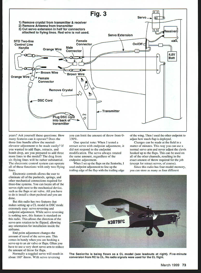
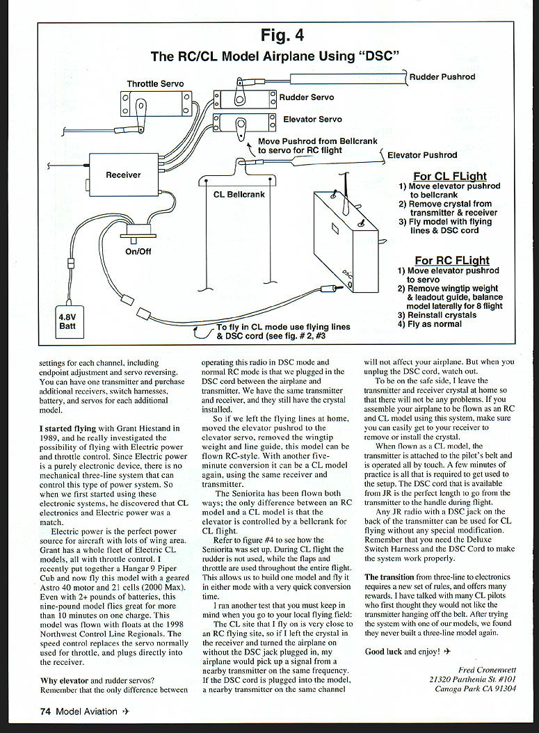
Why elevator and rudder servos?
The only difference between operating the radio in DSC mode and normal RC mode is the DSC cord plugged between the airplane and transmitter. The same transmitter and receiver (with crystal) are used. If you remove the flying lines and connect the elevator pushrod to an elevator servo, remove wingtip weight and line guide, the model can be flown RC-style. With a five-minute conversion it can be a CL model again using the same transmitter and receiver.
The Seniorita has been flown both ways; during CL flight the rudder is not used while flaps and throttle are active. Building one model that can fly RC or CL with a quick conversion is practical and convenient.
Safety note about crystals and nearby transmitters:
- If the receiver crystal remains installed and you power the RX with the DSC jack plugged in, a nearby transmitter on the same frequency could affect your airplane. While the DSC cord is plugged into the model, a nearby transmitter on the same channel will not affect it. But when the DSC cord is unplugged, the receiver could pick up other transmitters.
- To be safe, I leave the transmitter and receiver crystal at home when that risk exists, and I design the model so the receiver crystal can be removed/installed easily.
Operation tips
- During CL flight the transmitter is attached to the pilot's belt and operated by touch; a few minutes practice is all that is required.
- The JR DSC cord is a convenient length to reach from the transmitter to the handle during flight.
- Any JR radio with a DSC jack can be used for CL flying without special modification, but you must have the Deluxe Switch Harness and the DSC Cord.
The transition from three-line to electronic CL requires a new set of rules but offers many rewards. Many CL pilots who tried the transmitter-on-belt method never built another three-line model.
Good luck and enjoy!
Fred Cronenwett 21320 Parthenia St. #101 Canoga Park, CA 91304
Transcribed from original scans by AI. Minor OCR errors may remain.

