
Diva - 2005/02
by Phil Granderson
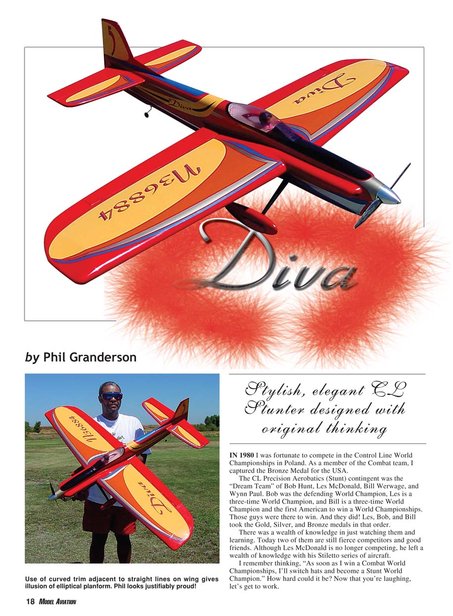
Stylish, elegant CL Stunter designed with original thinking
In 1980 I was fortunate to compete in the Control Line World Championships in Poland. As a member of the Combat team, I captured the bronze medal for the USA.
The CL Precision Aerobatics (Stunt) contingent was the "Dream Team" of Bob Hunt, Les McDonald, Bill Werwage, and Wynn Paul. Bob was the defending World Champion, Les is a three-time World Champion, and Bill is a three-time World Champion and the first American to win a World Championship. Those guys were there to win. And they did! Les, Bob, and Bill took the gold, silver, and bronze medals in that order.
There was a wealth of knowledge in just watching them and learning. Today two of them are still fierce competitors and good friends. Although Les McDonald is no longer competing, he left a wealth of knowledge with his Stiletto series of aircraft.
I remember thinking, "As soon as I win a Combat World Championship, I'll switch hats and become a Stunt World Champion." How hard could it be? Now that you're laughing, let's get to work.
Many people are looking for simplicity in a complex world. That was exactly my thinking when I began the Diva odyssey six years ago: just build a distinctive box around a proven formula. After exploring and observing a variety of proven formulas, it became apparent that this approach simply would not produce the airplane I envisioned. So what is Diva? It is the culmination of a few ideas and experiments that worked well and the exclusion of many ideas and experiments that either did not work at all or worked poorly. It is an original work. From the high cheek cowls to the canopy to the rudder, it is different. Top, front, and side views reveal that it is unique. The thinking and application of power is different. The airfoil is original. You might ask the question, Why reinvent the wheel? That was never my intention, but if you look closely you will see that the wheel was tweaked in some unique ways.
Beginning in the late 1960s there were experiments with extremely long tail moments, gapless hinge lines, variations on rudder offset, engine side thrust and downthrust, numerous airfoils, and far too many ideas and experiments with engines. Through all of that, somehow I still have old sketches, templates, and garbled notes tucked away in boxes and files that have been moved countless times. In November 1998 construction began on the first Diva. Rather than wading into the whole thing blindly, I applied a process that had proved successful for me and countless others: formulate a plan, make modifications when and where required, but, most important, never lose sight of the original goal. This had worked quite nicely in my Combat endeavors and in business.
So here's the plan: first, set a goal. You've probably heard the question, How will you get there if you don't know where you're going? The goal was to design and refine a world-class CL Aerobatics airplane. The model would someday win a World Championship—preferably with me as the pilot. Today I'm much closer and having so much fun that the only slightly painful chore so far is writing this article; I'd rather be building or flying!
The first Diva was promptly renamed "Ante" when my wife Kathleen observed that the paint scheme I planned did not look like a Diva. Ante was the first airplane to emerge from my clean-slate approach to design. Its maiden flight was eight months after I cut the first piece of wood.
This was the watershed project. I was going for the whole package: distinctive looks, front-row finish, piped engine, and world-class performance. The results fell somewhat short of the goal.
A summary of the results was that the finishing system worked well and was relatively easy to apply. Ante was a front-row airplane. The piped PA .65 engine performed well. The wing with the unique airfoil that was developed and implemented on the Triumph model built in 1969 worked exactly as I remembered it, generating a great deal of lift with no real side effects.
There were also some primary things that didn't work. I was completely baffled about why the tried-and-true combination of long tail moment and relatively small stabilizer/elevator size suddenly didn't work as it did on so many of my previous designs. Ante had no problem turning, but once the turn started it was difficult to get it stopped. I also noticed that it required more force on the handle to turn outside.
The design had an assortment of inherent problems that could not be corrected by adjusting, tweaking, and trimming. And finally, the line tension was way beyond my tolerance level.
I knew after roughly 20 flights with this airplane that the next model would have major modifications. Ante was left in its "best flight condition" and would serve as a measurement for changes and improvements to subsequent airplanes. To this day, it is still the control for all my experiments.
The second airplane—appropriately painted and approved for the name Diva—had four significant changes: equal-span panels, less wing area, the elevator and stabilizer were moved down closer to the thrustline, and the stabilizer/elevator area was increased to 26% of the wing area.
There were other changes too. The tail moment was shortened 1/2 inch to compensate for the larger stabilizer's additional weight. The wingtip shape was changed slightly. The flap area was reduced by 5%, and the fuel-tank compartment was expanded to allow the tank to be moved backward and forward an additional 2 inches. I also took much more care in the alignment and setup of the entire airplane.
Ultimately I installed the faithful PA .65. It was apparent from the first flights that these changes made significant improvements in the overall performance. The whole package seemed to come together. Most noticeable was the marked improvement in tracking. There was no more hunting, and the overturning problem was completely gone. Additionally, control pressure for outside and inside maneuvers was the same. Line tension was reduced slightly.
The Diva's finish was even slicker and shinier than the one applied to Ante. The horizontally adjustable tank proved to be golden for finding the perfect CG. I could move the CG aft or forward by 1 inch without adding weight.
Another bonus from the tank arrangement was that the CG did not shift as much from the beginning of the flight to the end. This was indeed a marked improvement over Ante. Flight scores immediately rose and were continuing to improve. It even captured my first Concours d'Elegance award.
I was just beginning to appreciate and enjoy the fruits of my labor when disaster struck. In what could only be called the dumbest thing I've ever done, my brain died and I hooked up the handle upside down and never did a preflight check! It's been said that few people have ever saved an airplane from crashing with the controls reversed. I was not one of the few!
The Diva's 36th flight is now memorialized by its unique dent in the blacktop at Whittier Narrows in Southern California. I still chuckle when I visualize Keith Trostle chasing it around the circle as the nose was firmly planted and the PA .65 chewed up the carbon propeller just before performing its brief fatal maneuver. No one ever imagined Keith could move that fast!
Within minutes of the disaster, the model's remains were loaded into the van and I started the six-hour drive home. I spent the first three hours of the drive chewing myself out and the next three planning my recovery.
I arrived home at 4:24 p.m., unloaded the van, got a sandwich, and began cutting balsa. By 7 p.m., I had the fuselage sides cut and the doublers clamped and laminated.
Construction of "Diva 2 Quick"
Construction of "Diva 2 Quick" progressed at breakneck speed. It was ready for the maiden flight August 28—just seven weeks after cutting the first piece of wood.
There were no big changes from its predecessor. I did make the stabilizer slightly bigger and added ribs to make it lighter. I lengthened the tail back to the original 21 inches used on the Ante. I also used thinner balsa for the rudder (3/16) and left it flat. It flew virtually the same as its forerunner and was easier to trim.
By all accounts and observations, everything worked very well. The model looked good, it flew really well, I looked comfortable flying it, and flight scores were on the rise again. It was fairly easy to "practice myself" into this airplane, but I wanted an airplane to practice with rather than one to practice for.
Wow, the truth can hurt! I had invested serious time, effort, wood, and money in creating a great airplane, and I wasn't happy. What would I have rather been flying? How about an airplane that was as positive as the Diva and as refined and nimble as a finely tuned Classic aircraft? As I sat in my shop, the Classic models began talking to me.
"Hey Phil, over here. I'm your Vulcan; I'll be nice to you. You can relax; fly me!"
"Me too! I'm your Lark; ditto what the Vulcan said."
The task was clear: tame and refine the 60-size airplane's edginess and brute force. I would have to break the mold that I painstakingly crafted in the first three airplanes. I would have to redesign, re-engineer, and reinvent a major portion of an excellent airplane.
Was there a smaller, lighter engine that would make the right kind and amount of power? What size should the new Diva be to score well when big airplanes generally score better? It was impractical to simply downsize Diva by a specific percentage.
The toughest task would be to find a readily available engine with the right kind and amount of power. It would also have to be light and manufactured to consistently high standards. If such an engine could be found and possessed good Stunt fundamentals, I was confident in my ability to identify and make modifications if necessary.
Believing that most modern .40-size engines had plenty of power, the quest began to find the best one for the refined Diva. I started collecting every 25- to 40-size engine I could find. Since I had conducted no tests, my only requirement was that it could not weigh more than 9½ ounces.
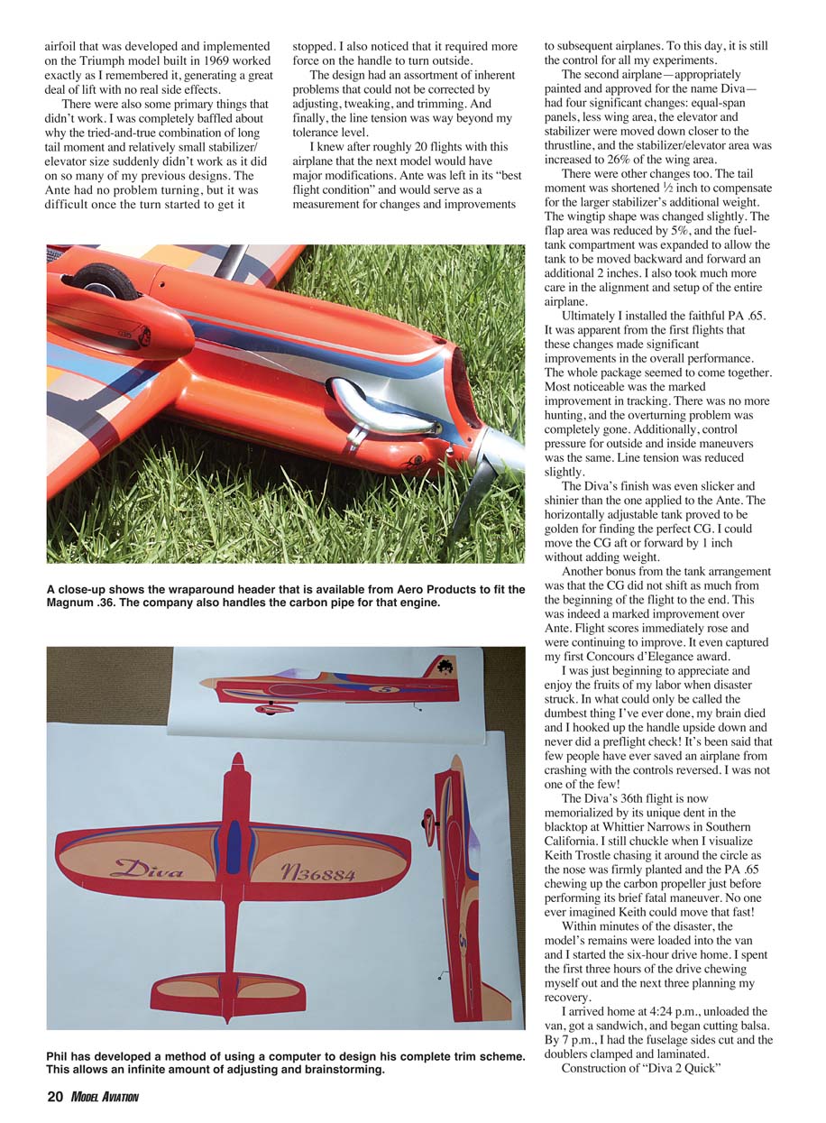
In December 2001 I began testing and evaluating eight engines. In the end, the Magnum .36 was clearly the top contender. It weighed only 8¼ ounces and easily turned an 11-inch propeller more than 11,000 rpm. The next step was to install a pipe and put the engine in a model to see if the power could be controlled.
The only airplane I was willing to sacrifice with all the modifications necessary was my 15-year-old El at, which had a 21-inch tail moment, 600 square inches of wing area, and weighed 54 ounces with the engine and pipe installed and ready to fly.
The first 20 flights were interesting in that most were spent finding the right pipe and length. I used a Bolly 12 x 4 narrow-blade propeller cut to 11 inches.
My suspicions about usable power were confirmed. There was definitely a great deal of power, and it seemed quite usable. Most of those flights were with the engine not running "on the pipe" and revealed a flat power curve and the smooth delivery of more power exactly when and where it was necessary.
At this point the pipe was just a muffler. The engine was happy being launched at a soft two-cycle and would break into a controlled faster speed the moment the nose was pointed up and then back into its soft phase as soon as the model returned to level. There was also no tendency to wind up or charge at any point. It seemed to "come on" in all the right places.
The first flight with the pipe in the range (on the pipe) produced a noticeably stronger feel everywhere in the pattern, and lap times went from 5.0 to 5.4. When the needle was turned in slightly to get to 5.2 lap times, the engine and airplane were ecstatic, and I couldn't keep myself from joining in the celebration by pushing that old model to previously unobtainable performance levels.
Since I felt comfortable with the engine, I was able to turn my focus to the new aircraft. It would have to be smaller and lighter but still have that "big airplane" presence. Deciding that it would probably be a series of design modifications, I decided to build the first version only slightly smaller than the previous .65-powered Divas.
The Ante has 750 square inches of wing area, and the two larger Divas have 710-square-inch wings. The wing area presented here is only 4% less; in fact, there is as much as in most modern .60-powered models that are flown today. The tail moment is 18.5 inches, which is slightly longer than most other airplanes. The fuselage is massive. The elevator/stabilizer area is medium to small compared to many models.
After the first flight, it was apparent that Diva IV was something special. My good friend Jim Aron remarked candidly, "I've seen the first flights of the previous airplanes, and this is the first time I've ever seen you smile!"
To date, there are two smaller Divas, each weighing 57 ounces. One has a foam-core wing with balsa sheeting, and the other uses the Lost Foam Wing Building System construction shown on the plans.
As an experiment, I used stick-on weights to increase the overall weight to 64 ounces, just to see what would happen. The only noticeable difference was more line tension. There was still plenty of power, and the Diva didn't hesitate anywhere in the pattern.
In general, the two primary components of any design are aerodynamics and power dynamics. Aerodynamics is the science of solid bodies moving through air. Diva was designed for competition from the beginning. It is an aerodynamic package that produces a stable solution for a set of complex and complicated variables.
Provisions have been made and tested that allow for the variety of adjustments necessary to bring the entire package into your personal comfort zone without adversely affecting visual presentation or limiting flight performance.
In our world, power dynamics consists of two primary components. For our purpose, the engine is a simple pump that converts fuel to energy and directs the energy to a specific output. Integral to this pump is a simple transmission system. It comprises the propeller and an adjustable exhaust timing device (tuned pipe).
The propeller acts as a gear and a final power converter. The pipe regulates the time, delivery, and consistency of power. It is a static throttle of sorts. The whole system is actually quite primitive because its components are overtly static, but it is elegant in its simplicity. When properly installed and adjusted, it delivers consistent, reliable, usable power.
So if that's all there is, why is it so difficult to get everything working the way you want?
How you attack a problem is the key. When you are on the flightline, how things work is far more important than why they work. These two factors should not be interchangeable, although frequently they are.
When you ask the question "How does it work?" the answer should be "good" or "bad." These answers ultimately quantify results because if you are honest, they confirm or deny the need for change.
When you ask "Why does it work?" the quest for an answer suddenly becomes complex. Ask those questions and see for yourself. An analogy would be that you don't have to know why a television works to be satisfied with how it works. This translates to our sport quite nicely. Ask how and make progress; ask why and ponder.
The preceding is not intended to be a brainteaser, but rather a systematic approach to problem solving and a foundation for performance building and enhancement.
Before beginning construction, let's look at the whole package
In the past six years of concentrated building and developing the Diva, I have come to understand and separate much fact from fiction. This process is not too different from my experiences in competitive Combat flying and business. Following are some facts I have learned.
- A good contest-caliber finish adds 7–10 ounces from bare wood.
- A light finish cannot save a heavy airplane.
- Good wood is 4–6 pounds per cubic foot. It is rare to find good wood that weighs less than 4.5 pounds, and, for our purposes, it should never exceed 6 pounds stock.
- In an aerodynamically well-designed airplane, weight distribution is far more important than weight conservation.
- The three most significant trim adjustments are CG, propeller, and control system. You can only use as much power as you need. Excess power will probably find a way to work against you.
Look closely at the plans and you will see some things that are out of the norm. These differences are what make the whole package work. Everything on the plans is there for a reason.
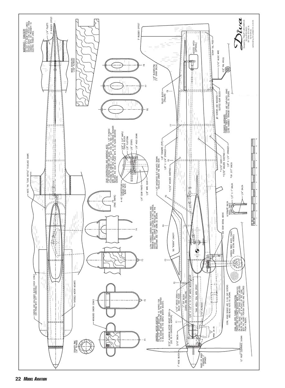
The majority of details relate to function. If you build the airplane per the plans—at a finished weight of 62 ounces or less—and build it accurately and straight, you will be pleased. Actually, the only frill is the little faux air scoop on the bottom of the cowl. Following are details of note.
- The fuselage gets wider at the midpoint and remains fairly wide where the stabilizer is mounted.
- The tank compartment is slightly wider than most, at 2 3/32 inches.
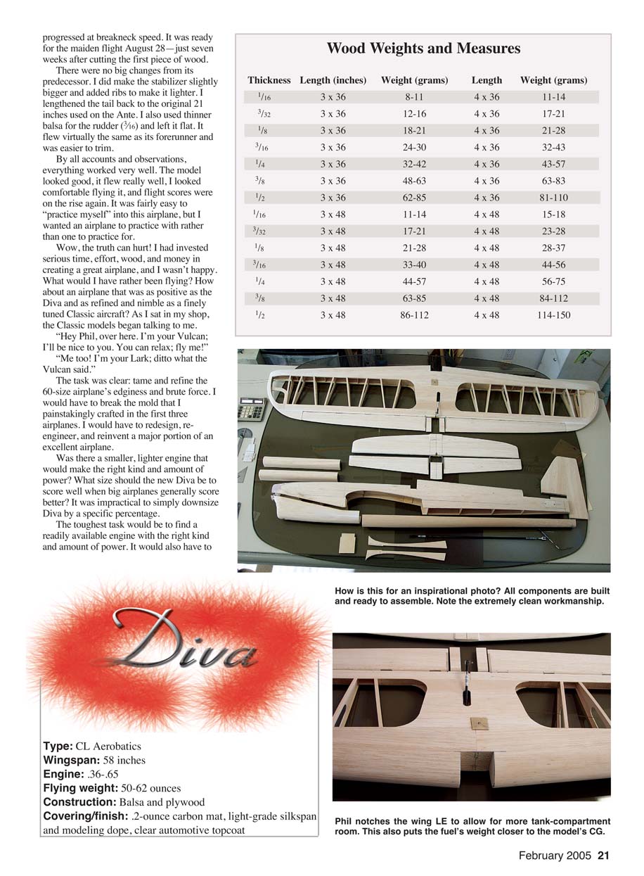
- The wing LE at the root inside the fuselage has a recessed cavity for tank adjustment.
- Cheek cowls terminate on the wing top at the high point of the root airfoil.
- The fuselage is deep at the dorsal fin. The rudder is 1/8 balsa.
- There is 3° of permanent rudder offset.
- There is no engine offset.
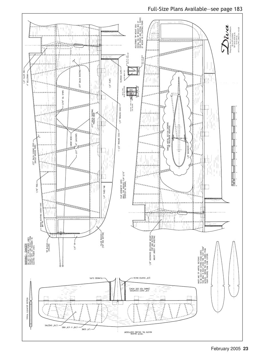
- The airfoil is completely different at the root than at the tip.
- The wing panels have equal spans.
- The outboard flap is 1/4 inch longer than the inboard flap.
- The control system is completely adjustable.
- There is a large air inlet in the cowl.
- The air outlet in the fuselage around the pipe is roughly three times that of the cowl inlet.
- Control horns are made from 7/32-inch-diameter wire.
Construction is probably not for a beginner, but an accomplished advanced competitor or builder should have no problem. Diva makes extensive use of molded-balsa components. The cheek cowls, aft fuselage top block, bottom fuselage block, most of the cowl, and LE sheeting are molded balsa.
Having built several wings using the Lost Foam Wing Building System, I do not hesitate to recommend it. The Diva IV has a traditional foam-core, balsa-sheathed wing that performs equal to the built-up wing.
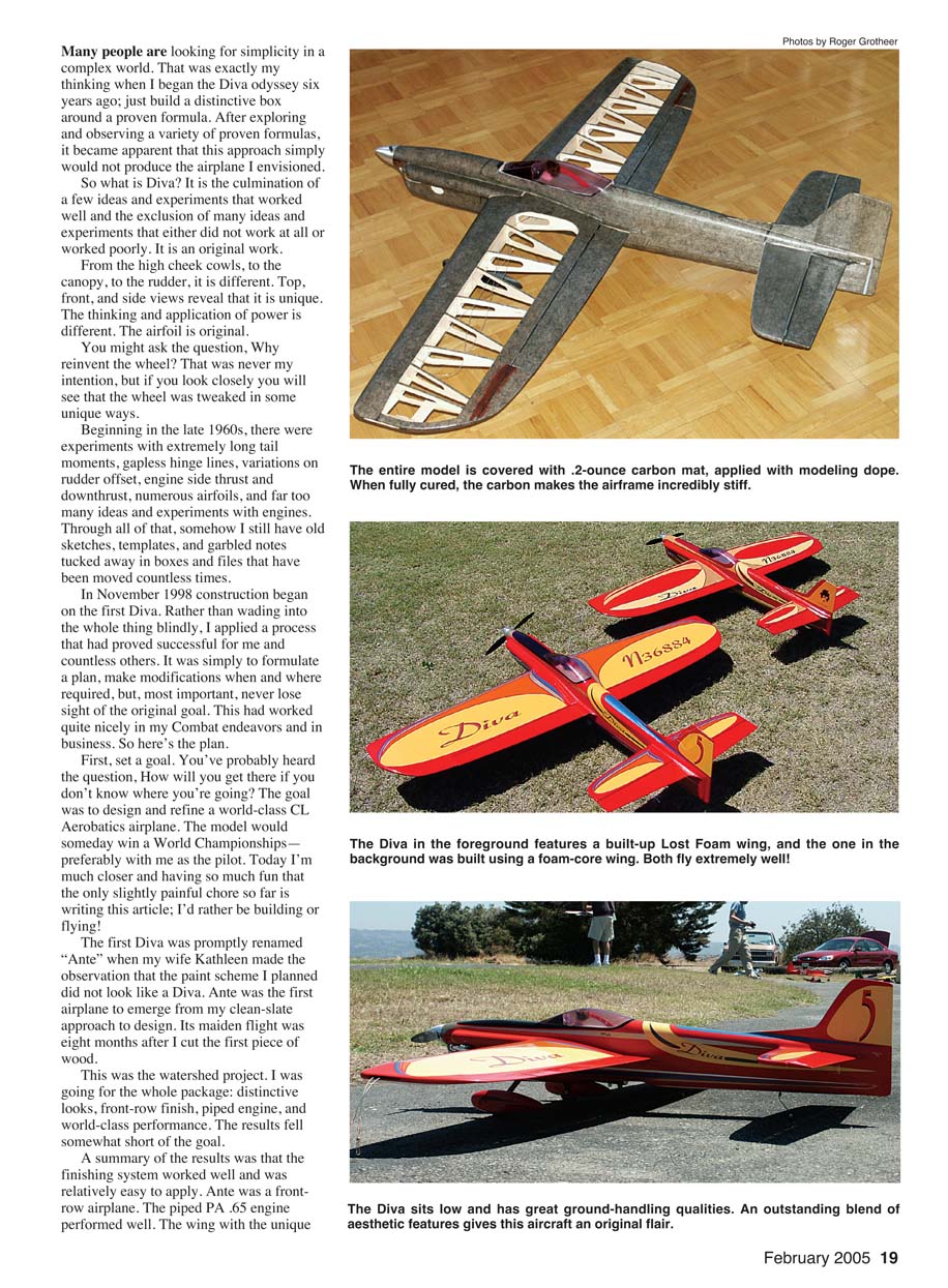
The entire model is covered with .02-ounce carbon veil before finishing. In a built-up wing, cover the entire structure—including open bays and rib capstrips—with the veil and cut the openings before final covering. Final wing covering of open bays is done with silkspan.
Wood selection is crucial for strength and weight. To a degree, type is less critical with the use of carbon veil before the final finish. The accompanying wood-weight chart refers to common balsa lengths and thicknesses, but the plans call for extensive use of .077-inch-thick wood. The weights for 1/16 wood in the chart should be close to those for the .077 wood.
Most custom-cut, contest-grade wood suppliers will cut the thicker wood when requested. As a general rule, it is preferable for thicker pieces to bias to the lighter side of the chart. You will also find exceptional wood that is actually lighter and obviously usable. The chart is only a gauge.
My favorite method of building is to complete entire components. I finish the wing with controls installed and tips and flaps shaped and fitted. Hinge slots and hinges are fitted.
I complete the fuselage with the cowl and front hold downs installed and all top blocks and 1/32-inch cross-grain sheeting on the bottom permanently glued, leaving only the opening for the wing. This is critical for final assembly because the fuselage can twist if it's not stabilized by permanent installation of major components.
The landing-gear mount and rear cowl hold down are integrated and can only be installed after the wing is permanently glued in. The elevator/stabilizer assembly is completely built, with all hinges aligned and test fitted. The control horn is permanently attached to the stabilizer. The rudder is completed with the dorsal fin.
Volumes have been written about construction methods. If you want to know more about two-stroke engines, Larry Scarrini's "Blitz" article from the mid-1960s is a must read. Bob Galdini's "Olympic" article from 1963 is the definitive work for CL Stunt aircraft-design considerations.
Robin's View Productions, Windy Urtnowski, and a host of other sources have produced videotapes chronicling everything from wood selection to finishing to installing tail wheels. Get your hands on as much information as you can and digest it. Your building will improve measurably and quickly as you gain knowledge.
As with any successful venture, countless people have made contributions. My grandmother helped me with words as I struggled to read model-airplane magazines when I was 7 years old. My mother was my lone defender when the house was filled with modeling-dope fumes and the rest of the family voted to disown me.
Mrs. Norton, who owned the local hobby shop, extended credit to me at the age of 16 and introduced me to Ed Southwick and Dick McCoy. This publication's aeromodeling editor has been a great friend for the past 30 years, and with him I have debated and shared thoughts on almost everything.
I must mention Brett Buck; in my humble opinion, he is the ultimate guru when it comes to trimming and adjusting just about anything on a Stunt model. There is also Jim Aron—one of very few who would ask for and actually get a piece of my best wood. And I can't leave out Ted Fancher and Dave Fitzgerald, who are my protagonists.
Then there is Larry "Mack" Mack, who actually designed and built the engine many years ago. He has been instrumental in the development of what I run today. Without his help this would not be possible.
I hope you've enjoyed the preceding and found it informative. As you persist in your quest for the perfect Stunt pattern, I leave you with one simple thought: rely on the fact that something is working to validate the fact that it does work.
Phil Granderson 13250 Campus Dr. Oakland, CA 94619
Wood Weights and Measures
- Thickness — Length — Weight (grams)
- 1/16
- 3 x 36: 8–11 g
- 4 x 36: 11–14 g
- 3 x 48: 11–14 g
- 4 x 48: 15–18 g
- 3/32
- 3 x 36: 12–16 g
- 4 x 36: 17–21 g
- 3 x 48: 17–21 g
- 4 x 48: 23–28 g
- 1/8
- 3 x 36: 18–21 g
- 4 x 36: 21–28 g
- 3 x 48: 21–28 g
- 4 x 48: 28–37 g
- 3/16
- 3 x 36: 24–30 g
- 4 x 36: 32–43 g
- 3 x 48: 33–40 g
- 4 x 48: 44–56 g
- 1/4
- 3 x 36: 32–42 g
- 4 x 36: 43–57 g
- 3 x 48: 44–57 g
- 4 x 48: 56–75 g
- 3/8
- 3 x 36: 48–63 g
- 4 x 36: 63–83 g
- 3 x 48: 63–85 g
- 4 x 48: 84–112 g
- 1/2
- 3 x 36: 62–85 g
- 4 x 36: 81–110 g
- 3 x 48: 86–112 g
- 4 x 48: 114–150 g
Specifications
- Type: CL Aerobatics
- Wingspan: 58 inches
- Engine: .36–.65
- Flying weight: 50–62 ounces
- Construction: Balsa and plywood
- Covering/finish: .02-ounce carbon veil, light-grade silkspan and modeling dope, clear automotive topcoat
Transcribed from original scans by AI. Minor OCR errors may remain.

