
Douglas XB-42 Mixmaster
Experimental "bug-eyed" bomber makes unique electric-powered model
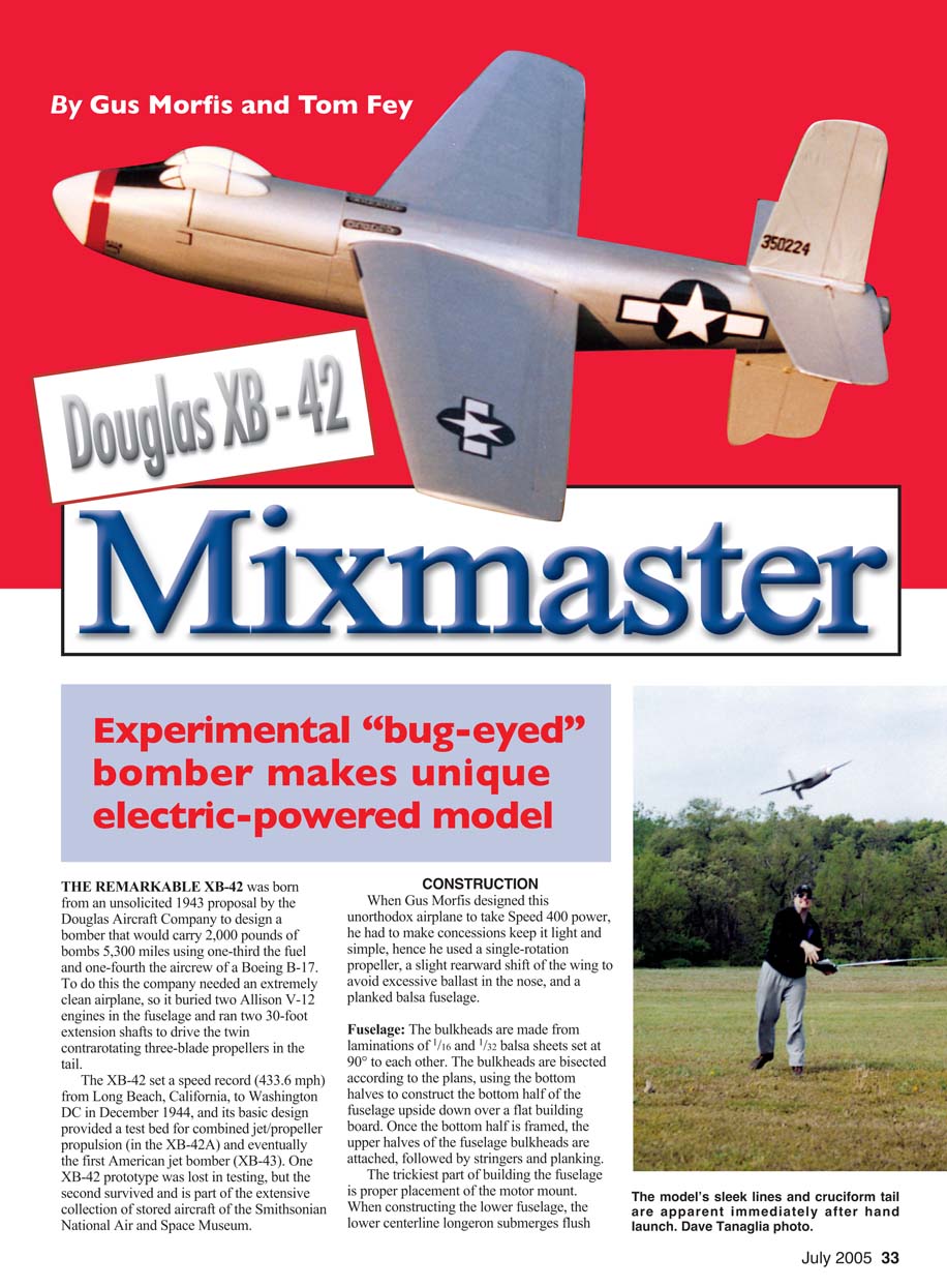
THE REMARKABLE XB-42 was born from an unsolicited 1943 proposal by the Douglas Aircraft Company to design a bomber that would carry 2,000 pounds of bombs 5,300 miles using one-third the fuel and one-fourth the aircrew of a Boeing B-17. To do this the company needed an extremely clean airplane, so it buried two Allison V-12 engines in the fuselage and ran two 30-foot extension shafts to drive the twin contrarotating three-blade propellers in the tail.
The XB-42 set a speed record (433.6 mph) from Long Beach, California, to Washington DC in December 1944, and its basic design provided a test bed for combined jet/propeller propulsion (in the XB-42A) and eventually the first American jet bomber (XB-43). One XB-42 prototype was lost in testing, but the second survived and is part of the extensive collection of stored aircraft of the Smithsonian National Air and Space Museum.
CONSTRUCTION
When Gus Morfis designed this unorthodox airplane to take Speed 400 power, he had to make concessions: keep it light and simple, hence he used a single-rotation propeller, a slight rearward shift of the wing to avoid excessive ballast in the nose, and a planked balsa fuselage.
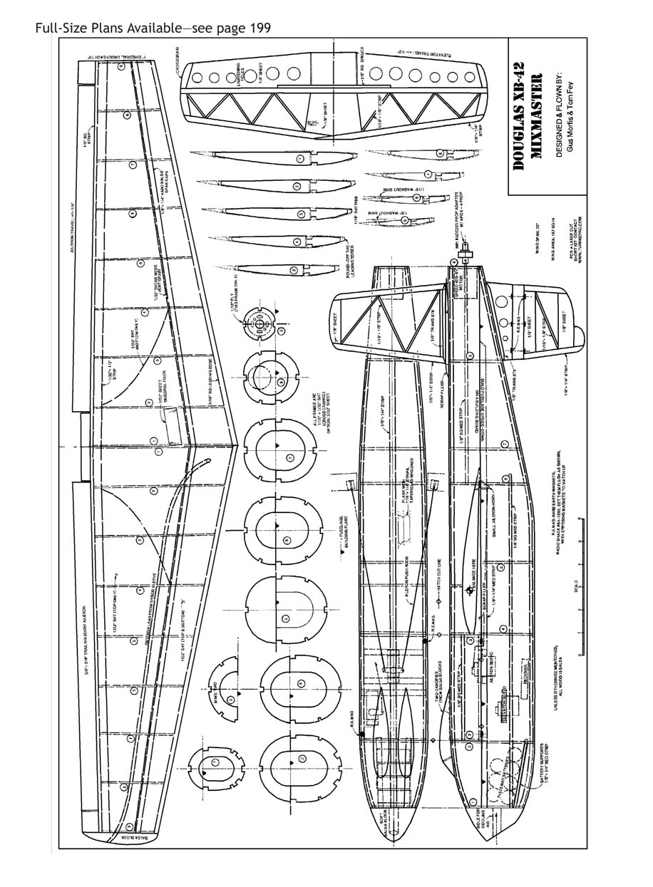
Fuselage: The bulkheads are made from laminations of 1/16 and 1/32 balsa sheets set at 90° to each other. The bulkheads are bisected according to the plans, using the bottom halves to construct the bottom half of the fuselage upside down over a flat building board. Once the bottom half is framed, the upper halves of the fuselage bulkheads are attached, followed by stringers and planking.
The trickiest part of building the fuselage is proper placement of the motor mount. When constructing the lower fuselage, the lower centerline longeron submerges flush with the formers so the motor plate can be installed later. The motor is placed well aft to keep the nose short and to allow proper balance with the pusher propeller at the tail. Mark two parallel lines on the longeron to show where the motor will be attached.
Once the lower fuselage is completely framed, align the framework upside down over the plans with the centerline of the fuselage 90° to the edge of a table. Using the marks on the longeron, place the motor mount on these marks, flush up against the edge of the table, and glue it in place.
When that's dry, flip the fuselage upright, attach the upper bulkheads, and glue the upper longerons and stringers in place everywhere except to the motor mount. Before final gluing, check the motor mount's alignment. Pin the framework keel flat over the plans, and then use a 90°-angle block to confirm that the mount is perpendicular to the building surface, thus set squarely in the framework with zero offset.
Once you have confirmed proper alignment, glue the longerons and stringers permanently to the motor mount.
Because the fuselage curves in more than one geometric plane, it has to be planked. The first step toward a smooth planking job is to carefully and gently sand the completed framework with a long bar sander to smooth the bulkheads and the framework. I tacked 1/8 square balsa across bulkheads 2, 4, 5, and 6 to rigidify the structure while sanding and planking, but I removed them as planking was nearing completion.
Make the 3/8-inch-wide, 1/16-inch-thick planks by shimming one side of a Master Airscrew Balsa Stripper with a piece of 1/4 square hardwood. Then draw the stripper across the balsa sheet to cut strips with the proper bevel in the edges as shown on the plans.
To prevent distorting the fuselage while planking, I planked three or four strips on one side of the fuselage, three or four on the other side, etc. Starting at the nose and working your way aft, tack a strip to each bulkhead using thin cyanoacrylate. Tuck the next plank closely into the glued pieces, glue it to the bulkheads, and then use a micro tip to apply small amounts of cyanoacrylate to the seam at 1/2-inch intervals.
Continue planking a strip at a time, alternating their up-and-down edges, and when the planking is complete, sand the planks flush with the bulkheads. Fit and glue the upper turtledeck sheeting, and sand the entire fuselage smooth. Install elevator control rods prior to closing with planking.
orientation to achieve a snug fit to each other as they wrap the fuselage exterior. Remember to insert the elevator pushrod guide (I used Kavan item HLFK0623) through the bulkheads and exiting the side before you finish planking the fuselage's top.
The ends of the new planks will eventually have to be custom-fit to mate with the existing planking. Test-fit the new strips in place, and mark the ends with a ruler using the seam line as a guide. Trim in length, angle, and bevel to make a tight fit with the existing planks, and then glue the plank in place. Careful work will yield a smooth exterior and a strong, lightweight fuselage. Do not plank the upper fuselage between bulkheads 2 and 4. That will become the access hatch.
To strengthen the lower fuselage after I finished sanding, I wrapped my gloved index finger with plastic food wrap and applied liberal amounts of thin cyanoacrylate to the fuselage, using my finger to rapidly spread the adhesive around. Beware of the heat and fumes that this technique generates!
Wing: Construct the wing over the plans, canting each rib 1 3.5° to give the desired 7° total dihedral. Shim the TE of rib 8 with a piece of 1/16 balsa and the TE of rib 9 with 1/8 balsa to add washout to the wing.
To keep the antenna out of the propeller arc, snake an antenna guide tube made from the yellow inner portion of a Sullivan Nyrod (item 503) through the right wing from root to tip.
To operate the ailerons, I ran the aileron pushrod sleeves internally through the wing and exiting the LE, but you can also run them under the wing and out the fuselage sides if you want. Although the prototype had an open framework, the plans have been changed to show that the top of the wing is completely sheeted with 1/32 balsa. The lower surface is sheeted only near the centerline, and aileron horns can be made from 1/32 plywood.
Glue triangular wedges made from 1/4 balsa sheet in place over the longerons behind bulkhead 4 to provide a wing saddle with the proper wing incidence. The wing should be covered, and the ailerons should be hinged, covered, and hung before the wing is epoxied permanently into the fuselage.
Remove the covering where the wing is glued to the fuselage so that wood is bonded to wood. Once the wing is glued in place, the top portion of bulkhead 5 can be trimmed to fit on top of the wing over the spars to support the upper longeron between bulkheads 4 and 6. Then the fuselage over the wing can be planked with 1/16 balsa and covered.
To frame up the removable hatch, place plastic food wrap over the fuselage between bulkheads 2 and 4. Pin the bulkhead 3 formers in place, and then glue in the upper 1/8 x 1/4-inch upper longeron and 1/8-inch square balsa stringers.
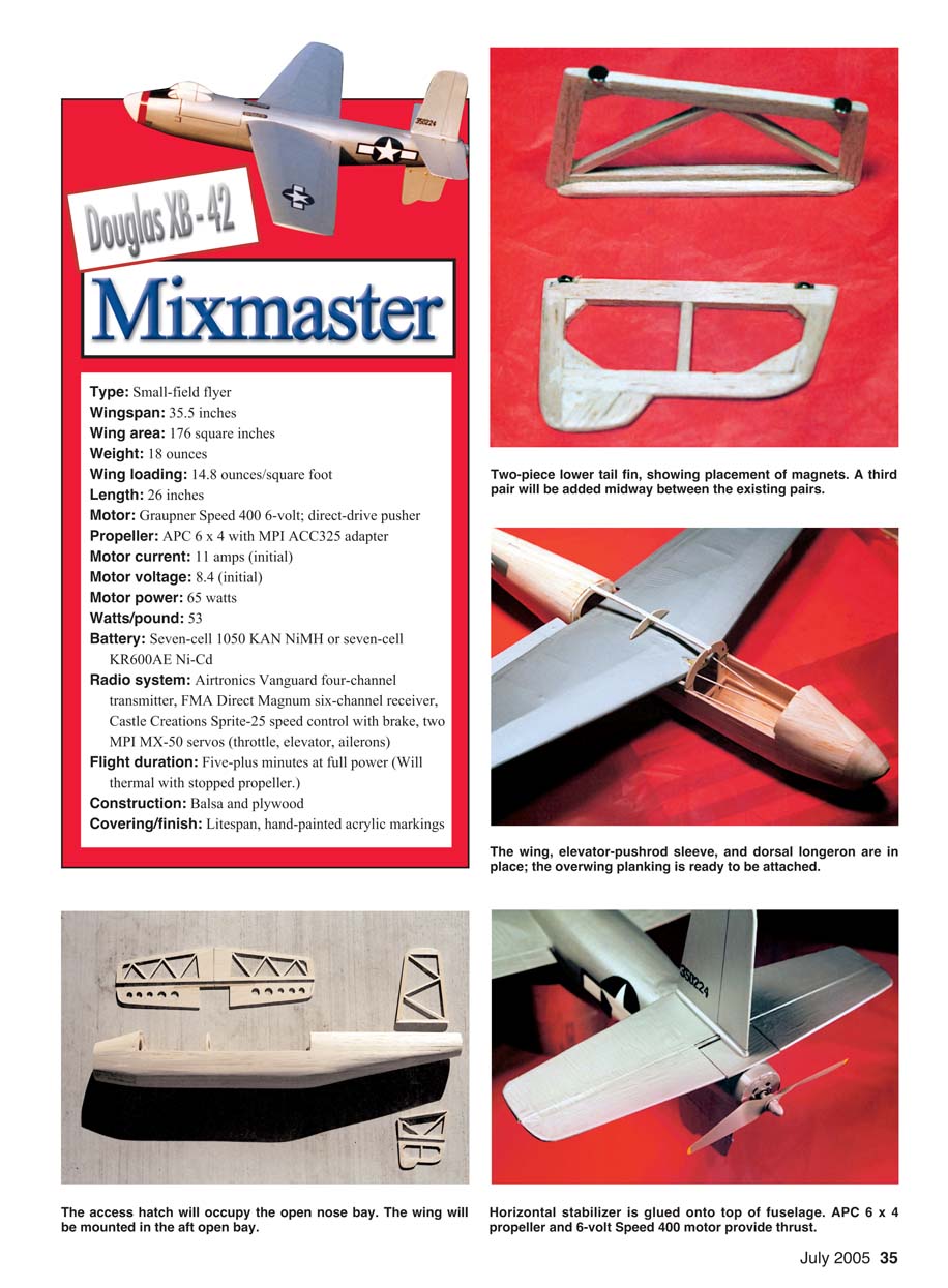
When this framework is dry, you can remove it from the fuselage and cover it with a piece of 1/16 balsa sheet. As the plans show, I used opposing sets of RadioShack rare earth magnets (catalog number 64-1895) set in balsa scrap to hold the hatch in place.
The nose is built up from lightweight balsa strips or a soft balsa block, and then sanded to conform to the outline on the plans. I bored a 3/8-inch-diameter hole, modified with a Dremel tool, to approximate the shape of the bombardier's window, through the nose to admit cooling air over the batteries and through the motor in the tail. The flight batteries rest in the nose on a carpet of hook-and-loop fastener glued to the floor of the nose compartment.
Tail Surfaces: The tail surfaces are built up flat over the plans from 1/8 balsa sticks and sheet stock. The lower fin is built in two sections to allow the lower portion to dislodge when landing.
After you have built and covered the lower fin, cut the three notches into each half of the fin. Glue the magnets into a half of the fin with gap-filling polyurethane glue, making sure that the fin is perpendicular to the building surface and the magnets are flat and flush with the edge of the fin while the glue dries.
When it's dry, cover the completed half of the fin with plastic food wrap and place the opposing pair of magnets over the magnets that are already fixed in place. Put a drop of glue on each magnet, place the other part of the fin in position, and repeat for the remaining half.
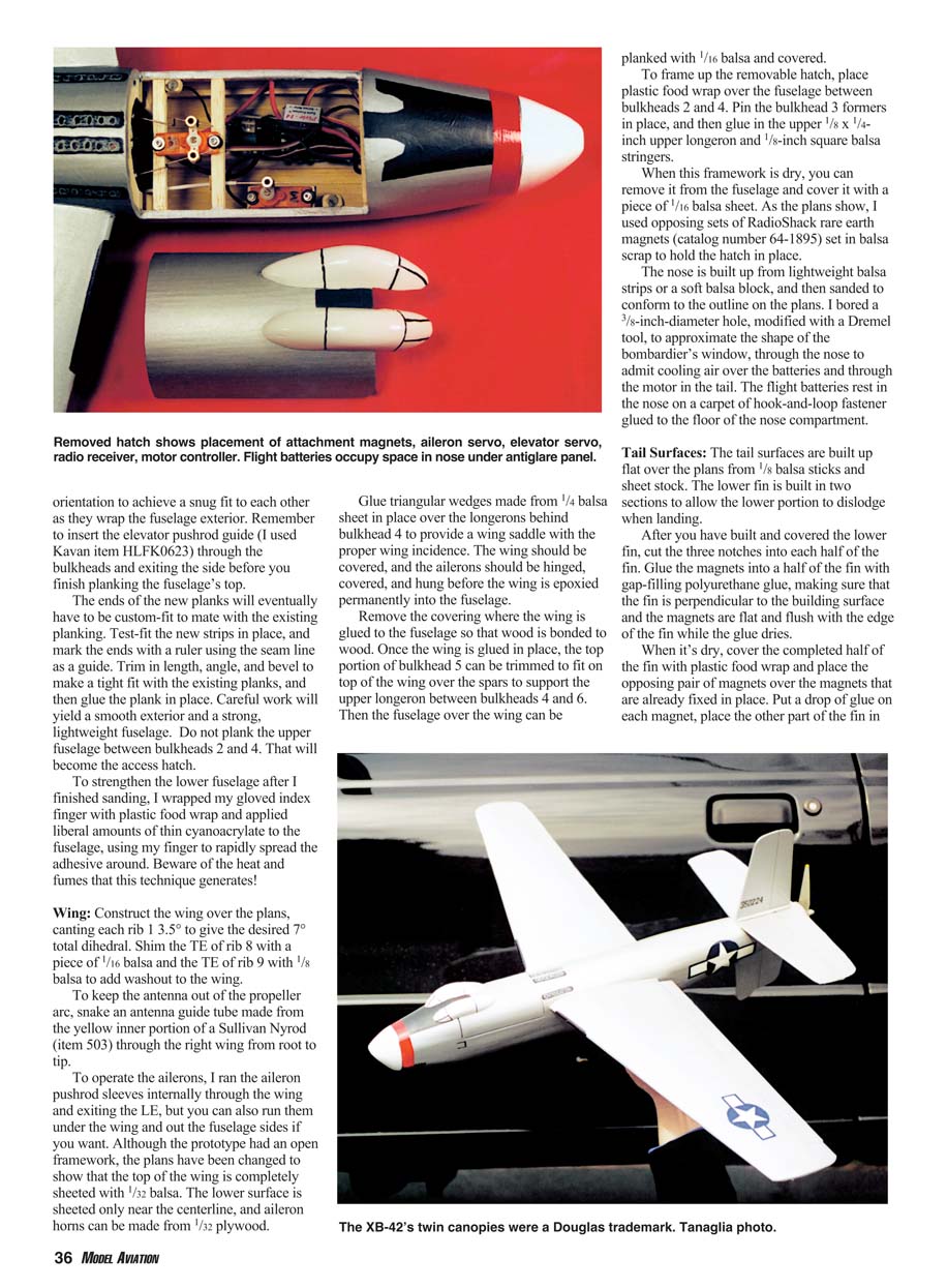
The XB-42's twin canopies were a Douglas trademark. Tanaglia photo.
Power System:
The flight components consisted of two MPI MX-50 servos, an FMA Direct Magnum receiver, a Castle Creations Sprite-25 speed controller with brake, 18-gauge wires for the extension back to the 6-volt Speed 400 motor, seven-cell KR600AE flight batteries, and an APC 6 x 4 propeller with MPI prop adapter (item ACC235).
Because of the pusher configuration, the motor should be connected with reverse polarity (+ wire from controller to - post on motor), and the standard tractor propeller should be mounted backward on the prop adapter.
Flying:
The XB-42 weighed 18.1 ounces (513 grams) ready to fly, which included a much-despised ounce of lead ballast in the nose. Adding an eighth flight battery or using a lighter-weight, brushless .02 motor would dispense with the need for ballast.
With a wing area of 178 square inches, the wing loading is a mild 14.6 ounces per square foot. The CG was adjusted so that the model balanced right on the lower wing spars where they exit the fuselage, control throws were set as noted on the plans, and I put two clicks of up-trim on the elevator for the first flight.
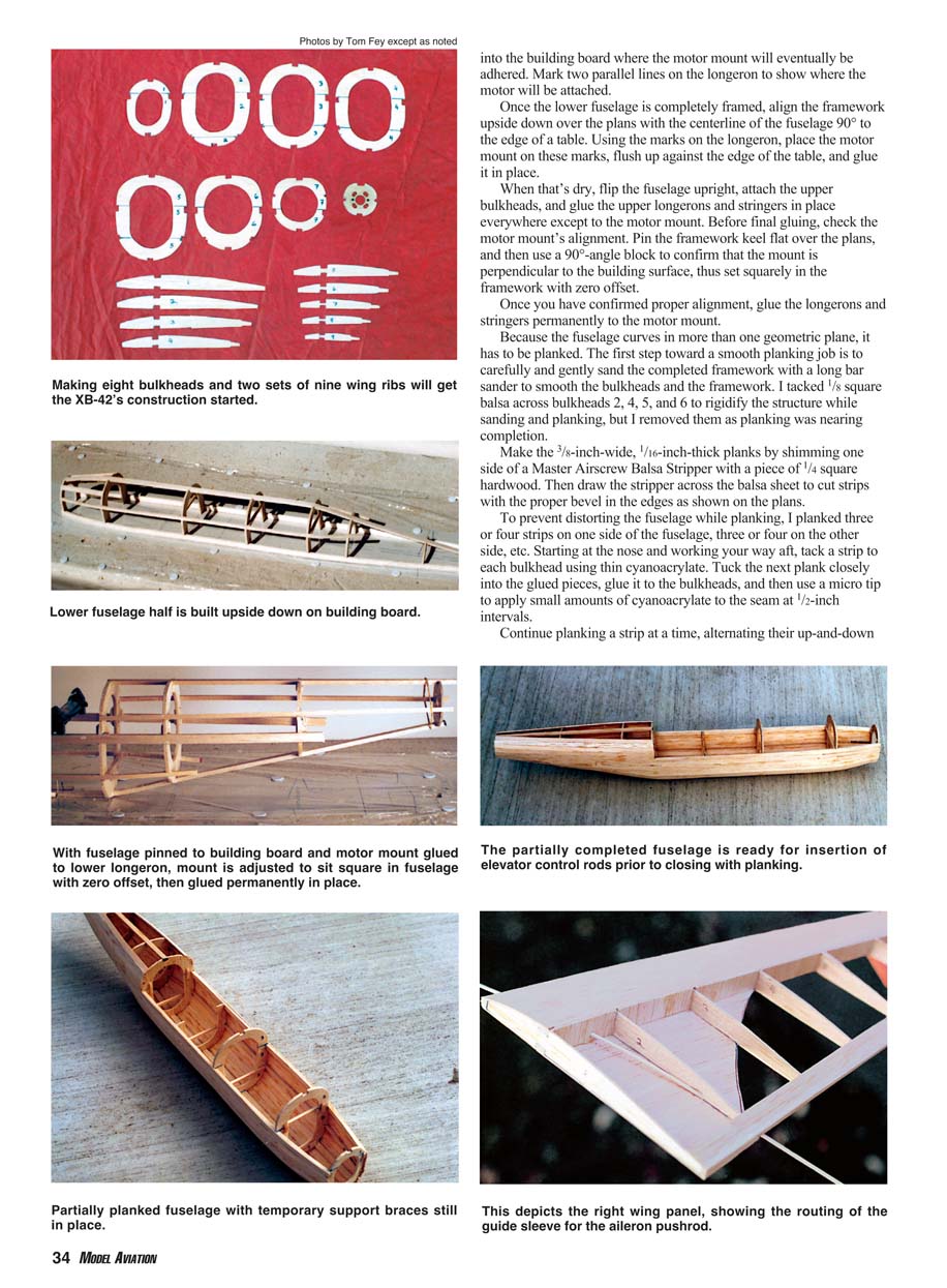
The XB-42 takes off briskly from a power-on, moderate-strength, flat-footed hand launch. I had no problem with the lower fin or propeller striking my launch hand. The airplane climbs exceptionally well, is surprisingly fast and stable, and cruises efficiently at approximately 35% throttle.
It loops and rolls nicely, and the stall is predictable with the nose falling straight forward. The lower fin can depart the aircraft on extremely gusty days, but the model flies perfectly well without it. The fin departs out of the propeller arc, so no damage is done.
Landing the XB is without surprises, but land it flat to avoid full-stall, tail-low landings that can damage the lower tail surfaces. It is best to have a prop brake on the motor controller to prevent damage to the lower fin or the motor mount from popping out when landing.
The XB-42 is a nice-flying, unique-looking model. Sure, it takes a little more work to build, but seeing it race around the sky like an aerial torpedo makes the handiwork well worth it. MA
Gus Morfis 4709 Green Meadows Ave. Torrance CA 90505 [email protected]
Tom Fey 918 E. Olive St. Arlington Heights IL 60004 [email protected] Full-Size Plans Available—see page 199
DOUGLAS XB-42 MIXMASTER
DESIGNED & FLOWN BY: Gus Morfis & Tom Fey
Transcribed from original scans by AI. Minor OCR errors may remain.

