
Drip Dry
Henry Smith The Oakland Cloud Dusters decided to renew Rise Off Water (ROW) events at the 1997 NorCal Free Flight Championships. In an effort to promote ROW Mulvihill, Carl Rambo donated the perpetual California State Fair Hydroplane trophy he won in 1941. The cup was to honor the memory of Joe Bilgri, a deceased OCD member who held Cat. I, II, and III ROW Mulvihill national records.
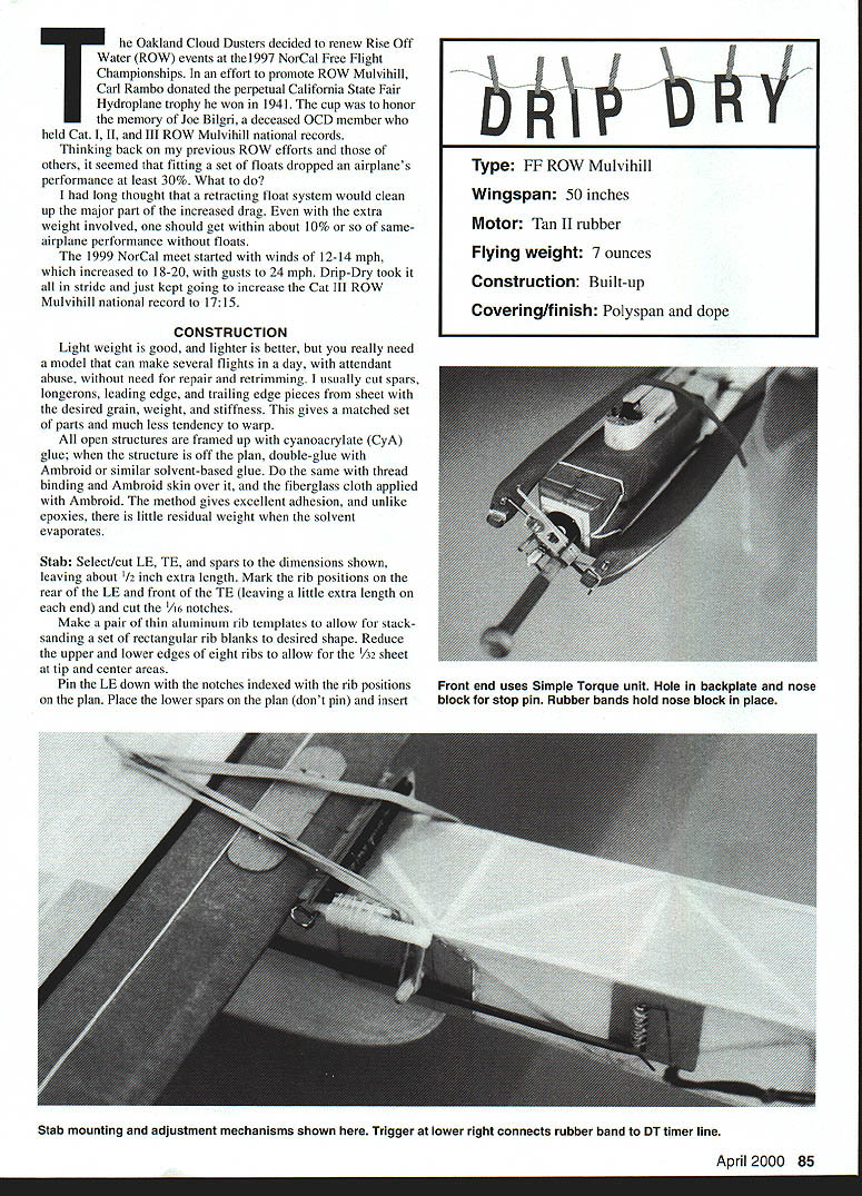
Thinking back on my previous ROW efforts and those of others, it seemed that fitting a set of floats dropped an airplane's performance at least 30%. What to do?
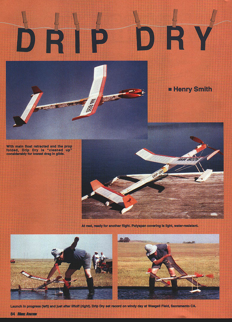
I had long thought that a retracting float system would clean up the major part of the increased drag. Even with the extra weight involved, one should get within about 10% or so of same-airplane performance without floats.
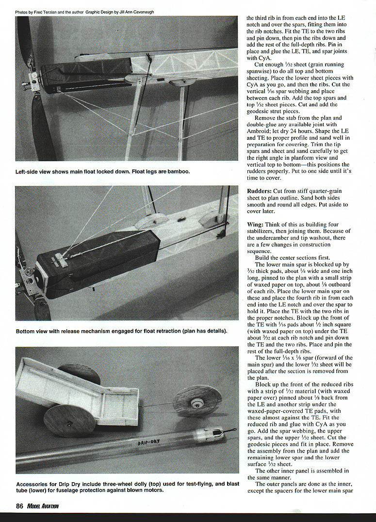
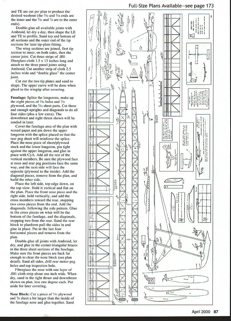
The 1999 NorCal meet started with winds of 12-14 mph, which increased to 18-20, with gusts to 24 mph. Drip-Dry took it all in stride and just kept going to increase the Cat III ROW Mulvihill national record to 17:15.
CONSTRUCTION
Light weight is good, and lighter is better, but you really need a model that can make several flights in a day, with attendant abuse, without need for repair and retrimming. I usually cut spars, longerons, leading edge, and trailing edge pieces from sheet with the desired grain, weight, and stiffness. This gives a matched set of parts and much less tendency to warp.
All open structures are framed up with cyanoacrylate (CyA) glue; when the structure is off the plan, double-glue with Ambroid or similar solvent-based glue. Do the same with thread binding and Ambroid skin over it, and the fiberglass cloth applied with Ambroid. The method gives excellent adhesion, and unlike epoxies, there is little residual weight when the solvent evaporates.
Stab: Select/cut LE, TE, and spars to the dimensions shown, leaving about 1/2 inch extra length. Mark the rib positions on the rear of the LE and front of the TE (leaving a little extra length on each end) and cut the 1/16 notches.
Make a pair of thin aluminum rib templates to allow for stacking a set of rectangular rib blanks to desired shape. Reduce the upper and lower edges of eight ribs to allow for the 1/32 sheet at tip and center areas.
Pin the LE down with the notches indexed with the rib positions on the plan. Place the lower spars on the plan (don't pin) and insert the third rib in from each end into the LE notch and over the spars, fitting them into the rib notches. Fit the TE to the two ribs and pin down, then pin the ribs down and add the rest of the full-depth ribs. Pin in place and glue the LE, TE, and spar joints with CyA.
Cut enough 1/32 sheet (grain running spanwise) to do all top and bottom sheeting. Place the lower sheet pieces with CyA as you go, and then the ribs. Cut the vertical 1/16 spar webbing and place between each rib. Add the top spars and top 1/32 sheet pieces. Cut and add the geodesic strut pieces.
Remove the stab from the plan and double-glue any available joint with Ambroid; let dry 24 hours. Shape the LE and TE to proper profile and sand well in preparation for covering. Trim the tip spars and sheet and sand carefully to get the right angle in planform view and vertical top to bottom—this positions the rudders properly. Put to one side until it's time to cover.
Rudders: Cut from stiff quarter-grain sheet to plan outline. Sand both sides smooth and round all edges. Put aside to cover later.
Wing: Think of this as building four stabilizers, then joining them. Because of the undercamber and tip washout, there are a few changes in construction sequence.
Build the center sections first.
The lower main spar is blocked up by 3/32 thick pads, about 1/4 wide and one inch long, pinned to the plan with a small strip of waxed paper on top, about 1/8 outboard of each rib. Place the lower main spar on these and place the fourth rib in from each end into the LE notch and over the spar to hold it. Place the TE with the two ribs in the proper notches. Block up the front of the TE with 1/16 pads about 1/2 inch square (with waxed paper on top) under the TE about 3/32 at each rib notch and pin down the TE and the two ribs. Place and pin the rest of the full-depth ribs.
The lower 1/16 x 1/8 spar (forward of the main spar) and the lower 1/32 sheet will be placed after the section is removed from the plan.
Block up the front of the reduced ribs with a strip of 1/32 material (with waxed paper over) pinned about 1/8 back from the LE and another strip under the waxed-paper-covered TE pads, with these almost against the TE. Fit the reduced rib and glue with CyA as you go. Add the spar webbing, the upper spars, and the upper 1/32 sheet. Cut the geodesic pieces and fit in place. Remove the assembly from the plan and add the remaining lower spar and the lower surface 1/32 sheet.
The other inner panel is assembled in the same manner.
The outer panels are done as the inner, except the spacers for the lower main spar are located inboard to obtain the required outboard washout at the tips. When joining the four panels, assemble the two inner panels and pin their LEs together on the plan. Fit the two outer panels to each inner panel and pin. Set the dihedral/washout by lifting the outer panels until the proper tip angle is obtained—use the plan view to get the correct angle. When satisfied, glue the joints with Ambroid and CyA. Add the wing-mounting dowels and plywood plate per plan. Shape the wing tips and sand smooth.
Covering and rigging follow the fuselage procedures. Cover the wing with lightweight tissue, seal with thinned nitrate dope, and finish with a final coat of clear dope.
Fuselage:
Splice the longerons, make up the eight pieces of 1/16 balsa and 1/32 plywood, and the 7/32 sheet parts. Cut these and enough uprights and diagonals to do all four sides (plus a few extras). The downthrust and right thrust shown will be sanded in later.
Cover the fuselage area of the plan with waxed paper and pin down the upper longeron with the splice placed so that the rear peg sheet will reinforce the splice. Place the nose piece of sheet-plywood stock and the lower longeron, pin tight against the upper longeron, and glue in place with CyA. Add all the rest of the vertical members. Be sure the plywood face at nose and rear peg positions face the same way, and the next side will face the opposite (plywood to the inside). Add the diagonal pieces, remove from the plan, and build the other side.
Place the left side, top edge down, on the top view. Hold it vertical and flat on the plan. Place the front nose piece and the right side, held vertically, and add the cross members toward the rear, stopping two cross pieces from the end. Add the diagonals, following the side pattern. Glue in the cross pieces on what will be the bottom of the fuselage, and the diagonals, stopping two from the rear. Sand the rear block to planform, pull the sides in and glue in place. Put in the last four horizontal pieces and remove from the plan.
Double-glue all joints with Ambroid, let dry, and glue in the corner triangular braces in the three sheet sections of the fuselage. Make sure the front pieces are back far enough to clear the nose block (see plan detail). Sand all sides, drill rear motor peg holes and top inspection hole.
Fiberglass the nose with one layer of .001 cloth strip about one inch wide. When dry, sand in the right thrust and downthrust shown on plan, less one degree each. Put aside for later covering.
Nose Block: Cut a piece of 1/32 plywood and 1/8 sheet a bit larger than the inside of the fuselage nose and glue together. Sand Cut a 1/8 x 1/4 notch in the center of the top surface and glue in the spruce key (see plan top view). Shape to match the nose profile and cut a matching notch in the top of the fuselage nose. Drill the center for a Simplex Torque front end and put aside for covering.
Prop Blades: Select the balsa blocks for either (or both) size(s) shown. Draw the side and top profiles as on the plan. Mark and drill the pivot hole. Cut the side profile, then the top.
I'm sure everyone has their own way to carve a prop, so that's up to you. Sand for covering and put aside.
Floats: These are essentially balsa boxes. Build the stab tip floats first, then the larger center rear float (just adding a center rib). The main float is built upside down on the flat top.
The Rest: Follow the plan specs for the various small plywood parts and the float/fuselage bearing blocks, DT timer/tracker block, bamboo support legs, and wire parts.
The DT trigger assembly is straightforward, but please drill a few holes on either side of the aluminum tube, through the plywood piece, and sew this on as well as gluing it in place. The triangular star hinge piece is cut as shown. Cut the 1/16 aluminum tube about 3/8 too long, to keep glue out of the ends. Likewise the spruce piece and the three carbon-fiber pieces are cut a little long to allow later fitting to the nylon fittings with no extra play.
Drill a few holes along the length of the spruce piece, through the plywood, lace all these pieces together, and glue with epoxy (see plan and photos). The threaded tubes for the 10-32 nylon screws are laced and epoxied into their plywood carriers in lace fashion with a small triangular balsa shim along each side.
Covering: All parts are given three coats of thinned nitrate dope, sanded lightly between coats. Think of Polyester (covering material for wing, fuselage, and stab) as silk or tissue, except that you use heat, not water, to go around corners.
Cover the rudders, prop blades, and wingtip plates with tissue (your choice of color). Give these pieces three coats of thinned nitrate, and lightly sand after the last coat. Add any tissue trim you want for decoration and tissue cover the noseblock if desired. The trim is placed with thinner, then dope. Add one more coat of dope on everything you covered.
ASSEMBLY
Wing: Add the turbulator (.012 thread) along the top of the first spar, using a small brush and nitrate dope. This doesn't seem to improve the glide angle, but it markedly improves the pitch recovery.
Prop blades: Insert 1/2 long 1/8 OD aluminum tubes in pivot holes and glue in place. Put the blades on the prop hangers, mark the position of the blade stop pins, drill or groove the prop end, and install using thread binding and Ambroid. Bend and fit the hooks for the prop-fold rubber bands.
Nose block: Drill for the Simplex unit and install per their instructions. Drill the stop hole in the backplate through the nose block for later use of a stop pin. Add hooks (see plan) for rubber bands to hold the unit on; assemble blades with retainers, front end with shaft, and this part is ready.
Fuselage: Add the forward pod for DT timer and tracker unit, the 1/16 plywood pieces for retract rubber band hooks, and the wing mount pieces. Drill a hole through the rear fuselage block to fit the threaded tube for stab incidence adjustment and glue in place. Add all hooks, DT trigger unit, float timer, and stab fittings.
Drill and add the 1/8 bamboo piece through the fittings and fuselage and glue in place. Do not add float pivot units or floats yet.
Drill and glue two 1/16 x 3/8 bamboo pegs at a rearward 45° angle through the 3/32 sheet (at the float timer station), being careful not to go into the longerons. There should be about 3/32 of peg exposed for later float line placement. Add the 3/32 sheet reinforcement piece for later float pivot block placement. Place and glue the 1/8 float release pin fittings, making sure the 1/2 dowel piece is bound through the underlying balsa/plywood nose piece for extra security.
Stab: Fit the triangular hinge piece by sanding each end to fit between the nylon bolt pivots so there is no end play, but it pivots easily with the pivot pin in place. Glue this to the bottom of the stab, making sure it is centered. Add the lower 1/64 plywood TE piece and the upper forward piece, drilling through it and the lower hinge piece and binding the pieces together. The 1/8 bamboo peg for DT bands is drilled at an angle through the center top sheet just behind the top main spar and emerges just in front of the lower main spar. Add the TE wire pigtail DT fitting and the turbulator slot.
Rudders: Block up the stab on 1/8 sheet pieces near each tip and butt-glue in place.
Rear floats: Glue on rear fuselage float and stab tip floats, positioned per plan and photos.
Main float: Assemble both bamboo float legs with all wire parts bound and glued. Put a 1/2 length of 1/16 aluminum tubing in all four float pivot blocks, per plan detail. Glue on the left (forward) fuselage pivot block and both main float pieces. Install the lower end of the front (shorter) and rear (longer) legs through float blocks with washers and solder. Attach the upper end of the front leg to the forward pivot block and add the loose block for later attachment. Put the float in retracted position, legs parallel along the fuselage sides, and glue the last pivot block in place. The main float should now swing freely up and down and lie flat on fuselage bottom when up, and have the proper positive angle when down.
DT: The rear line length allows a 45° pop-up on DT. With the button timer I use about 12 inches of 1/16 square, with the rest light braided fishing line. Adjust the tension to get about 60 seconds per 35–45° of rotation.
Main Float: Tie a one-inch loop in the middle of a six-foot length of 25-pound braided nylon fishing line. This is the forward stay loop.
Place the model on its side over the plan with the float in the extended position. Hold the loop with the release pin. Take one line from the loop and wrap it (two turns) around the forward leg four inches down from the pivot. Pull just snug and glue in place with Ambroid (CyA will "wick" too far). Do the same with the other line on the rear leg. Pull just snug and make sure the float is not pulled off center or into a twisted configuration, then glue.
Run the lines back and around the bamboo pegs near the float timer, pull tight, and tie. If the alignment is okay, glue the knot and around the pegs. Tie two loops about 3/8 long in six-inch lengths of the fishline, and tie these on each side where the stay lines are wrapped and glued (trim off the excess). If the strip of V ribbon under the front of the release pin has been glued into its job, it's still in place. Make up the four loops of 1/16 rubber to retract the float and install same.
Holding the fuselage behind the float retracted position, pull the pin; the float should retract smartly! Make the pin release line with about 1/2 inch of slack between the fully installed release pin and the timer arm loop when it is pulled against the timer stop. The length of line behind the timer depends on the rubber band used to drive the system. You need 2.5 inches or more line retraction and five to eight ounces of pull on the timer (see plan inset).
The takeoff dolly is recommended for practice.
Flight Adjustments: Make up a five-ounce motor of 1/4 Tan II and load in the fuselage. Put the fuselage in the stooge, mount the stab with the forward screw and adjust giving you rudder and no stab tilt and the bottom of stab parallel to the
Continued on page 92
Transcribed from original scans by AI. Minor OCR errors may remain.

