

Dump'r - 2003/10
Bob Kopski
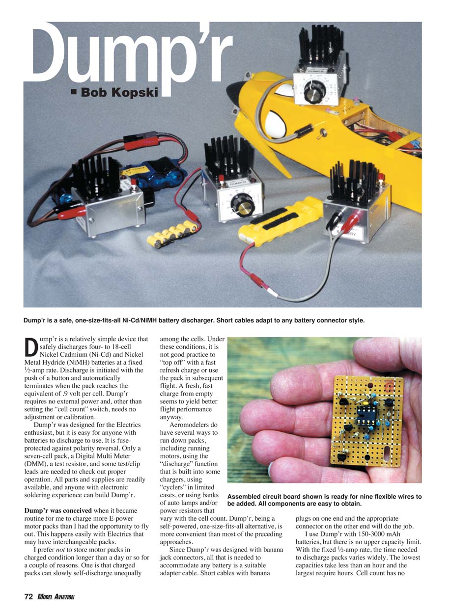
Dump'r is a relatively simple device that safely discharges four- to 18-cell Nickel Cadmium (Ni‑Cd) and Nickel Metal Hydride (NiMH) battery packs at a fixed 1/2‑amp rate. Discharge is initiated with the push of a button and automatically terminates when the pack reaches the equivalent of 0.9 volt per cell. Dump'r requires no external power and, other than setting the "cell count" switch, needs no adjustment or calibration. It is fuse‑protected against polarity reversal. Only a seven‑cell pack, a digital multimeter (DMM), a test resistor, and some test/clip leads are needed to verify proper operation. All parts and supplies are readily available, and anyone with electronic soldering experience can build Dump'r.
I conceived Dump'r because I often charged more E‑power motor packs than I could use immediately. I prefer not to store motor packs in a charged condition for long because cells can self‑discharge unequally; topping off such packs with a fast refresh charge is poor practice and can reduce flight performance. A fresh, fast charge from empty generally yields better results. Aeromodelers currently discharge packs by running motors, using charger discharge functions, cyclers, or banked lamps/resistors. Dump'r is a self‑powered, one‑size‑fits‑all alternative that is more convenient in many cases.
Because Dump'r uses banana jack connectors, any battery can be accommodated via a short adapter cable with banana plugs on one end and the appropriate battery connector on the other. I use Dump'r with 150–3000 mAh batteries, but there is no upper capacity limit. At the fixed 1/2‑amp rate, discharge time varies widely by capacity: small packs take under an hour, large packs may require several hours. Cell count does not affect discharge time.
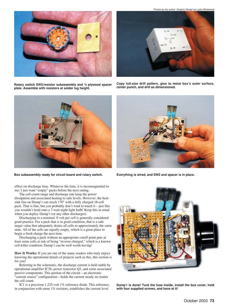
The cell‑count range and discharge rate keep power dissipation and heating to safe levels; however, the heatsink fins can reach about 170°F (about 77°C) with a fully charged 18‑cell pack. That is acceptable but you should avoid touching the heatsink during operation. Discharging to a nominal 0.9 volt per cell is considered good practice: for a healthy pack, this safely drains all cells to approximately the same state and prevents reverse charging, which kills cells. Dump'r is a useful tool to ensure uniformly emptied packs before a fresh charge.
How It Works
If you enjoy operational details, here's how Dump'r works:
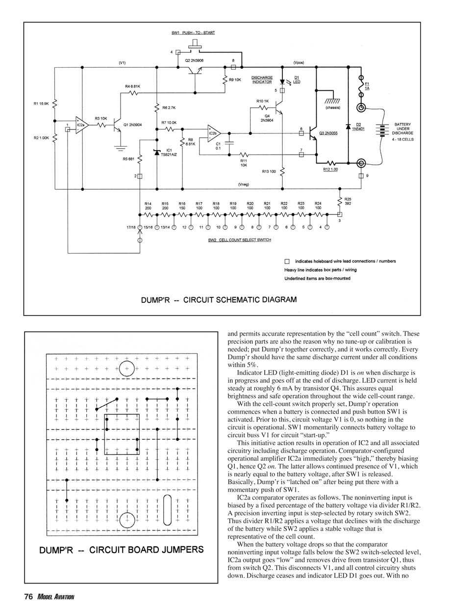
- The discharge current is held stable by op amp IC2b, power transistor Q3, and associated passive components. This section of the circuit is an electronic current source that maintains the current steady regardless of cell count.
- IC1 is a precision 1.225‑volt, 1% reference diode. With precision 1% resistors this reference establishes the current level for the current‑source portion of the circuit. Because the reference and resistors are precision parts, no calibration is needed; correctly built units should have the same discharge current within about 5%.
- Indicator LED D1 is on while discharge is in progress and goes off at the end of discharge. LED current is held at roughly 6 mA by transistor Q4 to assure consistent brightness and safe operation across the full cell‑count range.
- With the cell‑count switch (SW2) properly set, Dump'r operation starts when a battery is connected and pushbutton SW1 is momentarily pressed. Before SW1 is pressed circuit buss V1 is at 0 V and the circuit is off. Pressing SW1 connects battery voltage to V1 for circuit startup.
- On startup, IC2 and associated circuitry power up and discharge begins. Comparator IC2a immediately goes high, biasing Q1 and therefore turning on Q2. Q2 latches V1 on after SW1 is released so Dump'r remains running after the momentary press.
- IC2a comparator operation: the noninverting input is biased by a fixed percentage of battery voltage via divider R1/R2. The inverting input is a precision reference stepped by rotary switch SW2 (the cell‑count selector). As the battery discharges, the noninverting input voltage declines. When it falls below the SW2‑selected reference, IC2a output goes low, cutting drive to Q1 and Q2. This removes V1 and the control circuitry shuts down. Discharge stops and LED D1 goes out. With no battery voltage present the circuit must be restarted with SW1.
- With the switch set and a discharge in progress, there is negligible standby drain when the circuit is latched off, so it is safe to leave Dump'r connected until you can attend to the pack.
Cell‑count selection:
- The cell‑count switch selects cells individually from 4 through 12. Above that the switch advances by twos up to 18. The last three switch steps are electrically equivalent to 13½, 15½ and 17½ cells respectively. This representation is acceptable because available voltage resolution per cell diminishes at higher total voltages; the worst "volts per cell" error is about 0.035 V, which is acceptable.
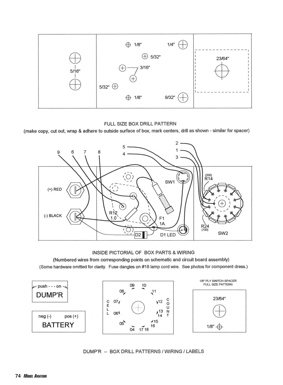
Full‑size Box Drill Pattern
- Make a copy of the drill pattern, cut it out, wrap and adhere it to the outside surface of the metal box, mark centers and drill as shown.
- Similar pattern applies to the spacer.
Inside Pictorial of Box Parts & Wiring
- Numbered wires correspond to points on the schematic and circuit board assembly.
- Some hardware omitted for clarity. The fuse is mounted on #18 lamp cord wire and dangles inside the box.
- Component layout summary (labels reproduced for reference):
- (+) RED, (-) BLACK
- R12 1.0
- D2
- F1 1A
- D1 LED
- SW1
- R14 (200)
- R24 (100)
- SW2
- Push button labeled "push - - - on"
- Front labels: DUMP'R, neg (-) pos (+), BATTERY
- Cell count positions shown with numbers 04–18 around switch
- 1/8" PLY SWITCH SPACER (full size pattern given)
- Spacer thickness: 1/8", drill size 23/64"
(Use the assembly drawings for exact hole locations and component placement. The pictorial is intended to aid wiring and component dressing.)
Building Dump'r
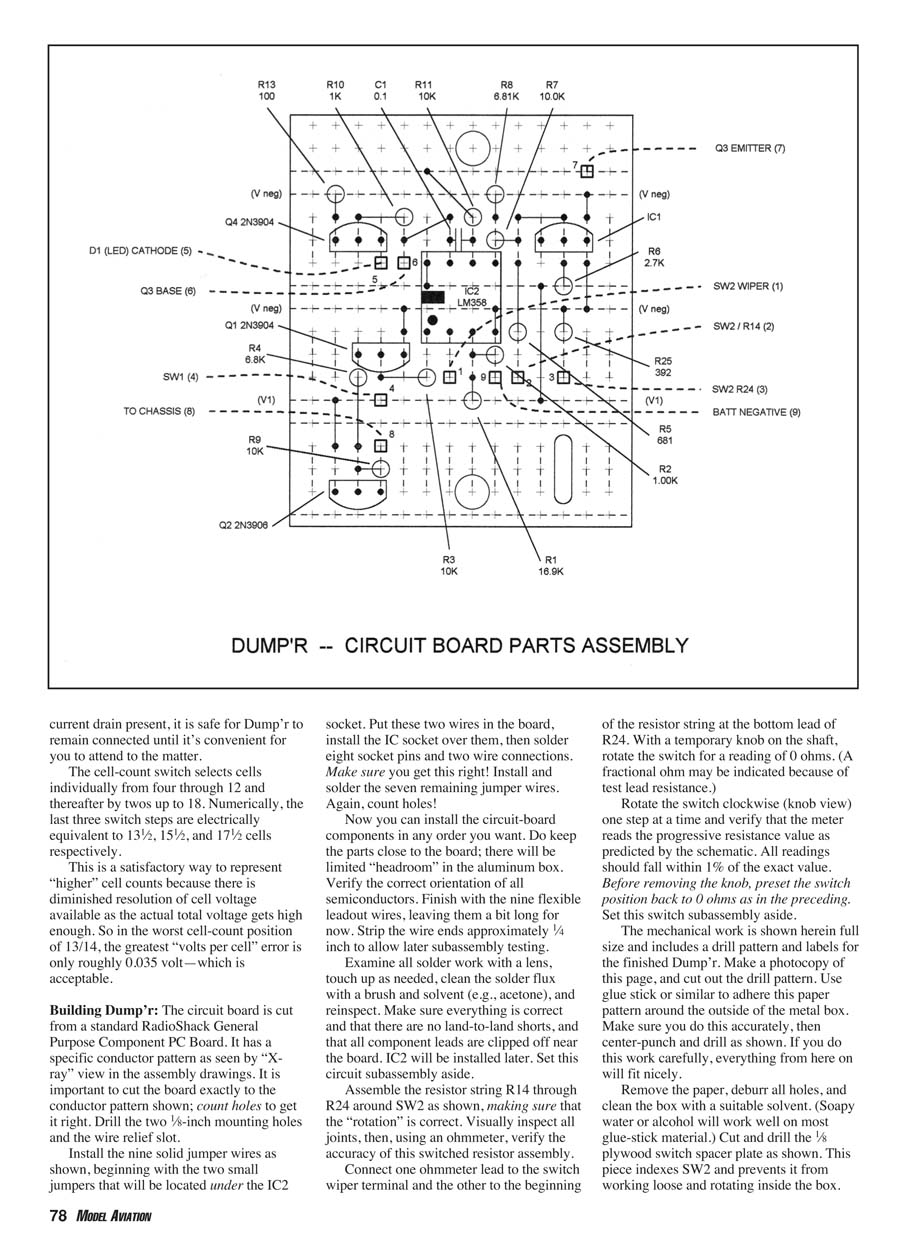
Circuit board:
- The circuit board is cut from a standard RadioShack general‑purpose component PC board. Cut the board exactly to the conductor pattern shown in the assembly drawings; count holes to get it right. Drill the two 1/8‑inch mounting holes and the wire relief slot.
- Install the nine solid jumper wires as shown. Begin with the two small jumpers that sit under the IC2 socket: place these two wires, install the IC socket over them, then solder eight socket pins and the two wire connections. Verify correctness, then install and solder the remaining seven jumpers. Count holes carefully.
- Install circuit‑board components in any practical order. Keep parts close to the board — there will be limited headroom in the aluminum box. Verify orientation of all semiconductors. Finish with the nine flexible leadout wires, leaving them a bit long. Strip approximately 1/4 inch of insulation for later subassembly testing.
- Inspect all solder joints with a lens, touch up as needed, clean flux with a brush and solvent (e.g., acetone), and reinspect. Ensure there are no land‑to‑land shorts and clip component leads near the board. Do not install IC2 yet; it will be installed later. Set the circuit assembly aside.
Resistor string around SW2:
- Assemble resistor string R14 through R24 around SW2, ensuring correct rotation. Visually inspect joints, then verify accuracy with an ohmmeter.
- Connect one ohmmeter lead to the switch wiper terminal and the other to the beginning of the resistor string at the bottom lead of R24. With a temporary knob on the shaft, rotate the switch to read 0 ohms (a fractional ohm may appear due to test lead resistance).
- Rotate the switch one step at a time and verify progressive resistance values match the schematic. All readings should be within 1% of the exact values. Reset the switch to 0 ohms and set the subassembly aside.
Mechanical work:
- Make a photocopy of the drill pattern and adhere it accurately to the metal box. Center‑punch and drill holes as shown. Deburr holes and clean off paper and adhesive with soapy water or alcohol.
- Cut and drill the 1/8‑inch plywood switch spacer plate as shown. This plate indexes SW2 and prevents it from loosening or rotating inside the box.
- Trial‑fit the spacer and SW2 in the box, then remove them for final assembly.
Box subassembly:
- Install the 1‑inch nylon standoffs using 4‑40 x 1/4‑inch pan‑head machine screws with inside star washers between the standoffs and the box.
- Install Q3 and the heat sink with 6‑32 x 1/2‑inch screws through the transistor mounting holes, the heat sink, 1/8‑inch spacers, then the box. The spacers are made from 6‑32 hex nuts drilled out to 5/32 inch to space the heat sink approximately 1/8 inch off the box.
- Inside the box, install one #6 inside star washer and the specified solder lug over the protruding screws followed by hex nuts.
- Install banana jacks, SW1, LED D1 and holder, diode D2 (observe polarity), resistor R25, and associated wires. Delay soldering the negative banana jack and the solder lug until later.
- Make fuse connectors using the specified clip leads of 18‑gauge lamp cord. Sweat‑solder the wire to the flat of the fuse clip and fully cover the clip with heat‑shrink tubing. Ensure thorough insulation.
- Glue labels to the box and protect them with clear tape or similar.
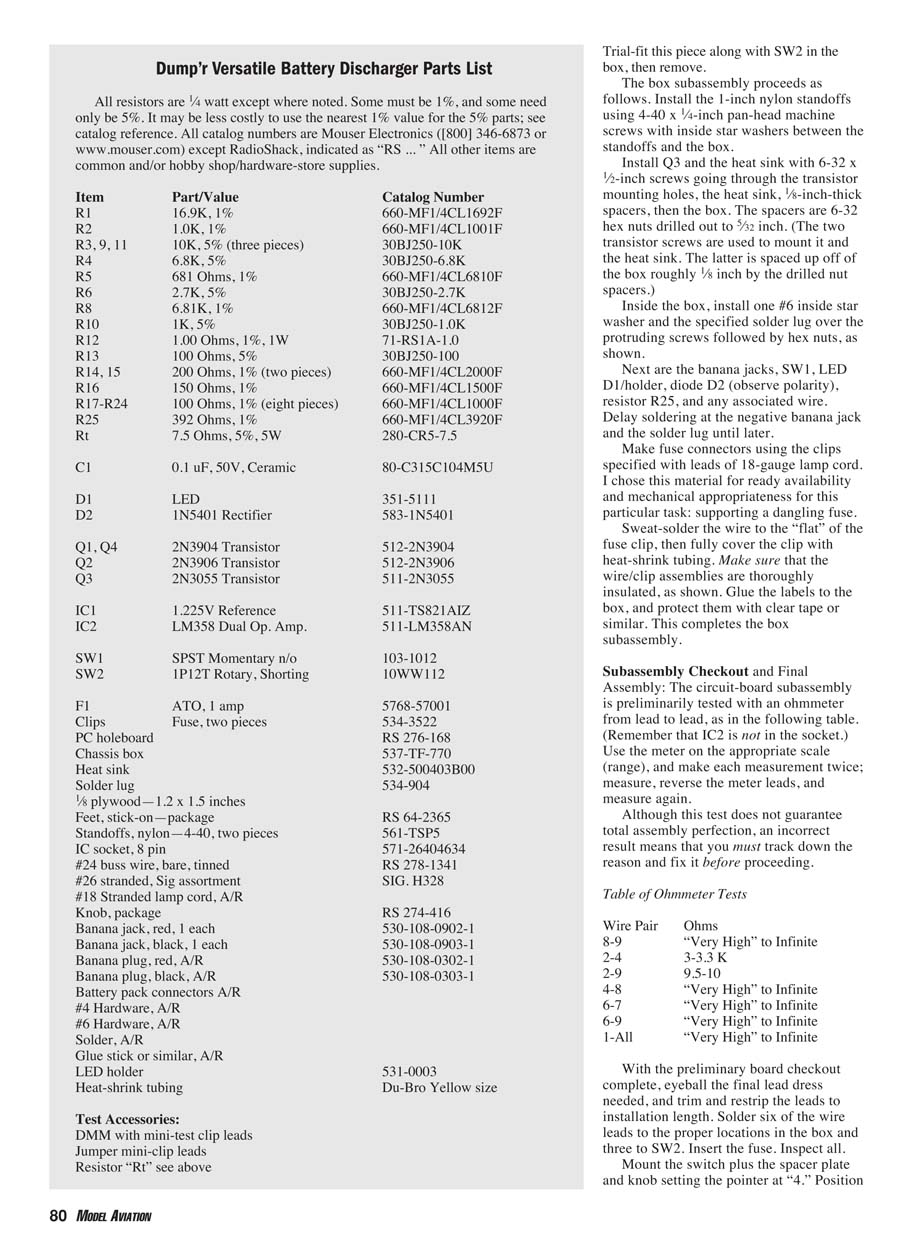
Dump'r Versatile Battery Discharger Parts List
All resistors are 1/4 watt except where noted. Some must be 1% tolerance; others may be 5%. It may be economical to use the nearest 1% values for some 5% parts. Catalog numbers are Mouser Electronics unless noted as RadioShack (RS).
- R1 — 16.9K, 1% — 660‑MF1/4CL1692F
- R2 — 1.0K, 1% — 660‑MF1/4CL1001F
- R3, R9, R11 — 10K, 5% (three pieces) — 30BJ250‑10K
- R4 — 6.8K, 5% — 30BJ250‑6.8K
- R5 — 681 Ω, 1% — 660‑MF1/4CL6810F
- R6 — 2.7K, 5% — 30BJ250‑2.7K
- R8 — 6.8K, 1% — 660‑MF1/4CL6812F
- R10 — 1K, 5% — 30BJ250‑1.0K
- R12 — 1.00 Ω, 1%, 1W — 71‑RS1A‑1.0
- R13 — 100 Ω, 5% — 30BJ250‑100
- R14, R15 — 200 Ω, 1% (two pieces) — 660‑MF1/4CL2000F
- R16 — 150 Ω, 1% — 660‑MF1/4CL1500F
- R17–R24 — 100 Ω, 1% (eight pieces) — 660‑MF1/4CL1000F
- R25 — 392 Ω, 1% — 660‑MF1/4CL3920F
- Rt — 7.5 Ω, 5%, 5W — 280‑CR5‑7.5
- C1 — 0.1 µF, 50 V, ceramic — 80‑C315C104M5U
- D1 — LED — 351‑5111
- D2 — 1N5401 rectifier — 583‑1N5401
- Q1, Q4 — 2N3904 transistors — 512‑2N3904
- Q2 — 2N3906 transistor — 512‑2N3906
- Q3 — 2N3055 transistor — 511‑2N3055
- IC1 — 1.225 V reference — 511‑TS821AIZ
- IC2 — LM358 dual op amp — 511‑LM358AN
- SW1 — SPST momentary normally open — 103‑1012
- SW2 — 1P12T rotary, shorting — 10WW112
- F1 — ATO, 1 amp — 5768‑57001
- Clips — Fuse clips, two pieces — 534‑3522
- PC holeboard — RS 276‑168
- Chassis box — 537‑FT‑770
- Heat sink — 532‑500403B00
- Solder lug — 534‑904
- 1/8" plywood — 1.2 x 1.5 inches — RS 64‑2365
- Feet, stick‑on (package) — RS 64‑2365
- Standoffs, nylon — 4‑40, two pieces — 561‑TSP5
- IC socket, 8‑pin — 571‑26404634
- #24 buss wire, bare, tinned — RS 278‑1341
- #26 stranded, signal assortment — SIG. H328
- #18 stranded lamp cord — as required
- Knob, package — RS 274‑416
- Banana jack, red — 530‑108‑0902‑1
- Banana jack, black — 530‑108‑0903‑1
- Banana plug, red — 530‑108‑0302‑1
- Banana plug, black — 530‑108‑0303‑1
- Battery pack connectors — as required
- #4 hardware — as required
- #6 hardware — as required
- Solder — as required
- Glue stick or similar — as required
- LED holder — 531‑0003
- Heat‑shrink tubing — Du‑Bro yellow size
Test accessories:
- DMM with mini‑test clip leads
- Jumper mini‑clip leads
- Resistor Rt (7.5 Ω, 5 W) as above
Box Subassembly and Mounting Details
- Trial‑fit the plywood spacer and SW2, then remove them.
- Install the nylon standoffs with 4‑40 x 1/4‑inch screws and inside star washers.
- Mount Q3 and heat sink with 6‑32 x 1/2‑inch screws through transistor, heat sink, drilled hex‑nut spacers, then the box. Inside the box, add an inside star washer and solder lug over each protruding screw, then hex nuts.
- Install banana jacks, SW1, LED D1 with holder, diode D2 (observe polarity), resistor R25 and wiring. Delay soldering at the negative banana jack and the solder lug until wiring is finalized.
- Make fused leads using 18‑gauge lamp cord and the specified fuse clips; sweat‑solder the wire to the flat of the clip and cover with heat‑shrink. Ensure clips are thoroughly insulated.
- Glue and protect labels with clear tape.
Subassembly Checkout and Final Assembly
Preliminary circuit‑board checks (IC2 not installed):
- Use an ohmmeter on the appropriate range. Make each measurement twice: measure, reverse meter leads, and measure again. Incorrect results must be fixed before proceeding.
Ohmmeter tests:
- Wire 8–9: Very high to infinite
- Wire 2–4: 3.0–3.3 KΩ
- Wire 9–5: 9.5–10 KΩ
- Wire 4–8: Very high to infinite
- Wire 6–7: Very high to infinite
- Wire 1–All: Very high to infinite
Final lead dress:
- Trim and restring leads to final installation length.
- Solder six wire leads to the proper box locations and three to SW2.
- Insert the fuse and inspect the assembly.
- Mount the switch with spacer plate and knob, setting the pointer at "4".
- Position the circuit board on the nylon standoffs and secure with 4‑40 x 1/4‑inch screws.
- Install IC2 into its socket (observe orientation).
- Connect an ohmmeter to the banana jacks: reading should be very high to infinite depending on lead polarity and meter scale. Press SW1 and verify a reading of about 3.5–4.0 KΩ; the reading should be the same with the meter leads reversed.
Preliminary Power‑Up Test
Required items:
- Charged seven‑cell Ni‑Cd or NiMH pack
- 7.5‑ohm test resistor Rt
- Assorted test clip/meter leads
- Digital voltmeter (DVM)
Test procedure:
- Connect Rt in series with the battery and Dump'r so Rt is in one lead from the battery to Dump'r. Connect the DVM across Rt.
- With LED off and no button pressed there should be no voltage across Rt.
- Press SW1. LED should light and DVM should read ~3.75 V (0.5 A × 7.5 Ω).
- Advance the cell‑count switch one step at a time. The LED should go out at switch position 5 or maybe 6 depending on exact pack voltage. When LED goes out voltmeter across Rt should drop to 0 V.
- If OK, remove Rt and DVM and connect the battery directly to Dump'r. Set SW2 to 7 and press SW1: LED should come on. Move switch to 8 (or 9 depending on pack voltage) and LED should go out.
- Reset SW2 to 7, press SW1 and allow the pack to discharge. LED should eventually go out. Use a voltmeter across the battery to watch progress; discharge should stop near 0.9 × 7 = 6.3 V.
- For deeper analysis, a lab variable power supply and ammeter can be used to observe steady current while varying cell‑count or supply voltage.
When testing is finished, remove the dangling fuse inside the box, install the box cover and cover screws, and optionally fit stick‑on rubber feet to the box bottom.
Troubleshooting and Support
- If you experience trouble building or operating Dump'r, the author offers assistance including troubleshooting and repair (free except for postage). Contact:
- Bob Kopski
- 25 West End Dr.
- Lansdale, PA 19446
Happy dumping! MA Bob Kopski
Transcribed from original scans by AI. Minor OCR errors may remain.

