
Duster
Bill Winter & John Hunton
Editor's note: As this article was being prepared, we learned of the passing of Bill Winter on December 11, 1998. Our sympathies to his family and his many friends and associates in modeling.
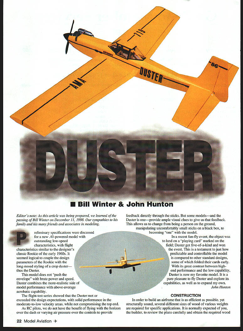
Preliminary specifications were discussed for a new .40-powered model with outstanding low-speed characteristics, with flight characteristics similar to the designer's classic Rookie of the early 1960s. It seemed logical to couple the design parameters of the Rookie with the long-nosed styling of a crop duster—thus the Duster.
This model does not "push the envelope" with brute power and speed. Duster combines the more-realistic side of model performance with above-average aerobatic capability.
The flight-test series showed that the Duster met or exceeded the design expectations, with solid performance in the moderate-to-low velocity areas, while not compromising the top end.
As RC pilots, we do not have the benefit of flying with the horizon over the dash or varying air pressure over the controls to provide feedback directly through the sticks. But some models—and the Duster is one—provide ample visual clues to give us that feedback. This allows us to change from being a person on the ground, manipulating uncomfortably small sticks on a black box, to becoming "one" with the model.
In a recent fun-fly event, the object was to land on a "playing card" marked on the field; Duster got five-of-a-kind and won the event. This is a testament to just how predictable and controllable the model is compared to other standard designs, some of which folded their cards early. With its great contrast between high-end performance and low-speed capability, Duster is now my favorite model. It is a pure pleasure to fly Duster and explore its capabilities, as well as to expand my own.
John Hunton
Design Overview
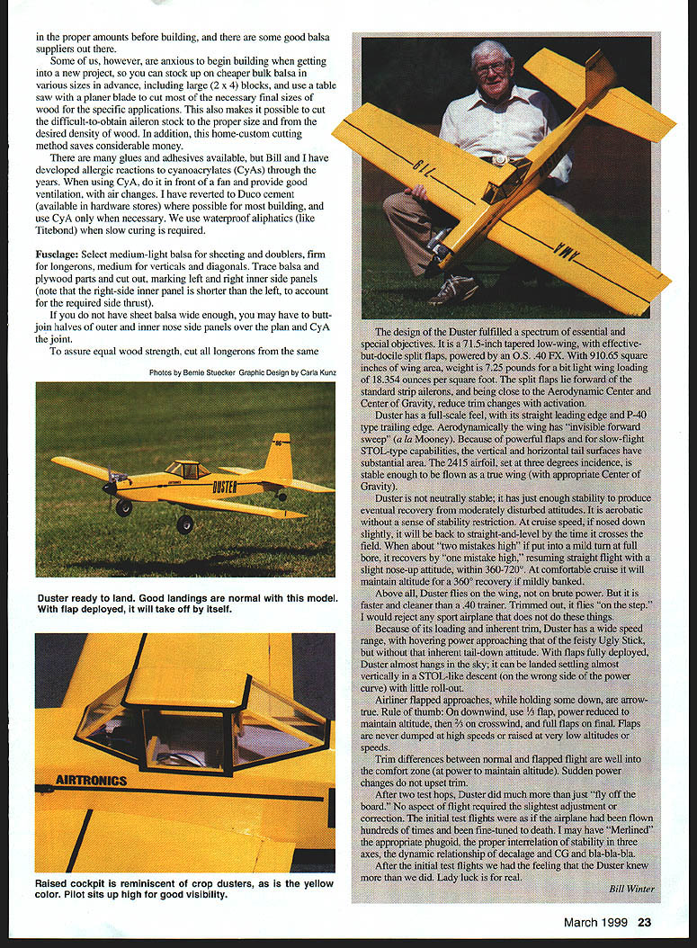
The Duster fulfilled a spectrum of essential and special objectives. It is a 71.5-inch tapered low-wing with effective but docile split flaps, powered by an O.S. .40 FX. With 910.65 square inches of wing area, weight is 7.25 pounds for a light wing loading of 18.354 ounces per square foot. The split flaps lie forward of the standard strip ailerons and, being close to the aerodynamic center and center of gravity, reduce trim changes with activation.
Duster has a full-scale feel, with its straight leading edge and P-40–type trailing edge. Aerodynamically the wing has "invisible forward sweep" (a la Mooney). Because of powerful flaps and STOL-type capabilities, the vertical and horizontal tail surfaces have substantial area. The 2415 airfoil, set at three degrees incidence, is stable enough to be flown as a true wing with the appropriate center of gravity.
Duster is not neutrally stable; it has just enough stability to produce eventual recovery from moderately disturbed attitudes. It is acrobatic without a sense of stability restriction. At cruise speed, if nosed down slightly, it will be back to straight-and-level by the time it crosses the field. When about "two mistakes high," if put into a mild turn with full bore, it recovers by "one mistake high," resuming straight flight with a slight nose-up attitude. At comfortable cruise it will maintain altitude for a 360° recovery if mildly banked.
Above all, Duster flies on the wing, not on brute power. But it is faster and cleaner than a .40 trainer. Trimmed out, it flies "on the step." Because of its loading and inherent trim, Duster has a wide speed range, with hovering power approaching that of the feisty Ugly Stick, but without that inherent tail-down attitude. With flaps fully deployed, Duster almost hangs in the sky; it can be landed settling almost vertically in a STOL-like descent (on the wrong side of the power curve) with little roll-out.
Airliner-flapped approaches, while holding some down, are arrow-true. Rule of thumb: on downwind use 1/2 flap and reduce power to maintain altitude; 3/4 flap on crosswind; full flaps on final. Flaps are never used at high speeds or raised at very low altitudes or speeds. Trim differences between normal and flapped flight are well within the comfort zone (at power to maintain altitude). Sudden power changes do not upset trim.
After two test hops, Duster did much more than just "fly off the board." No aspect of flight required the slightest adjustment or correction. The initial test flights felt as if the airplane had been flown hundreds of times and been fine-tuned to death. After the initial test flights we had the feeling that the Duster knew more than we did. Lady luck is for real.
Bill Winter
Construction
In order to build an airframe as efficient as possible, yet structurally sound, several different sizes of wood of various weights are required for specific applications. It is normally expected of the builder to review the plans carefully and obtain the required wood.
Some builders prefer to stock up on cheaper bulk balsa in various sizes in advance (including large 2 × 4 blocks) and use a table saw with a planer blade to cut most of the necessary final sizes for specific applications. This also makes it possible to cut difficult-to-obtain aileron stock to the proper size and density of wood and saves considerable money.
Glues and adhesives
- Cyanoacrylates (CyA) are common but can cause allergic reactions. If using CyA, work in front of a fan and provide good ventilation.
- Duco cement (hardware-store type) is used where possible for most building; CyA is used only when necessary.
- Use waterproof aliphatic glues (like Titebond) when slow curing is required.
- For hinge installation and other high-stress joints, epoxy is recommended.
Fuselage
Materials
- Medium-light balsa for sheeting and doublers
- Firm longerons
- Medium balsa for verticals and diagonals
- Aircraft plywood for firewall and selected formers
Procedure
- Trace balsa and plywood parts and cut out parts. Mark left and right inner side panels (note: the right-side inner panel is shorter than the left to account for required side thrust).
- If sheet balsa is not wide enough, butt-join halves of outer and inner nose side panels over the plan and CyA the joint.
- To assure equal wood strength, cut all longerons from the same stock.
- Pin longerons down on the plan, seat, and glue outer side panels. Cut crosspieces from long blocks to final length to ensure accurate fit. Install crosspieces and diagonals.
- After the side subassembly is dry, remove pins and block-sand both sides smooth.
- Mask off the nose area, spray adhesive (3M Super 77 or equivalent) lightly on one panel and the inner panel, wait until tacky, then join panels carefully, applying pressure for good adhesion.
- Mark locations of elements attached to the side plates. Cut and install triangular side corner reinforcement, tank floor rails, cockpit side rails, and cabin reinforcement.
- Build the opposite side similarly.
- Cut balsa and plywood formers. Use aircraft-type plywood for the firewall and former C from Lite Ply. Glue counter-grain reinforcing formers B and F. Cut the tank floor/servo mounting plate. Install blind nuts and firewall motor mount. Cut cockpit formers from Lite Ply.
- Begin fuselage assembly by dry-fitting formers on both sides to ensure good fit. Install formers C through F and the bottom plate at station F on the side fuselage. Add the opposite side using slow-curing glue, being certain all formers seat in their slots.
- Install tank floor to make assembly rigid. Lay the assembly top down over the plan (block up the rear 3/4 inch) to check alignment and let dry. Install all fuselage crosspieces and check the tailpost carefully for verticality during this operation.
- Install the firewall and its balsa cross-supports, noting that down-thrust and right-offset are as designed. Install the side plates at the pushrod exits.
- Seal all openings in the motor area with tissue/tape and install the motor with its mount to the firewall.
- Install all servos and linkages while access is good. Install the rear turtledeck, top nose sheeting, and cabin parts.
- Install the top and bottom nose plates, but check-fit the fuel tank first. The top may have to be hollowed slightly for the tank to be located near the centerline of the needle valve.
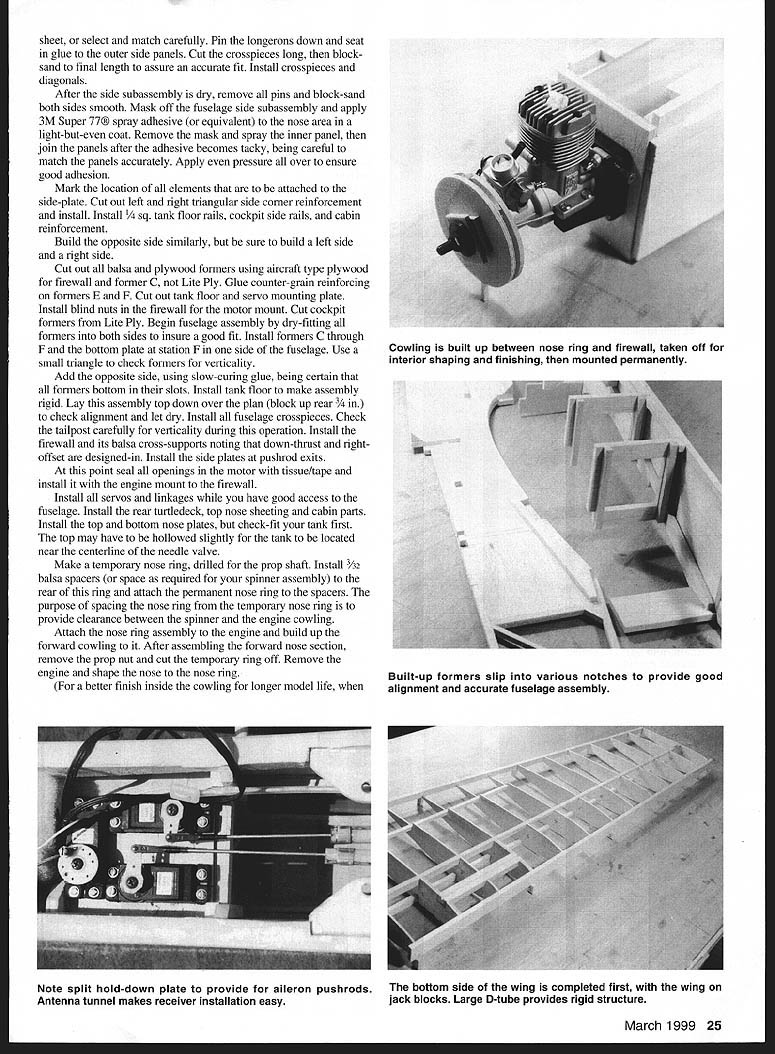
- Make a temporary nose ring drilled for the prop shaft. Install 3/32 balsa spacers (or space as required for your spinner assembly) to the rear of this ring and attach the permanent nose ring to the spacers. Spacing provides clearance between the spinner and the engine cowling.
- Attach the nose ring assembly to the engine and build up the forward cowling to it. After assembling the forward nose section, remove the prop nut and cut the temporary ring off. Remove the engine and shape the nose to the nose ring.
- For a better finish inside the cowling and longer model life: when building the nose up, apply waxed paper to the firewall area, remove the cowling to finish the interior, then reattach after hooking up fuel lines, linkages, etc.
Wing
Materials
- Medium/light wood for ailerons
- Medium wood for ribs and leading edges
- Firm, straight-grained wood (spruce or similar) for spars
- Pliable balsa sheeting for the leading-edge D-tube
- Aircraft plywood half-ribs for root area
Procedure
- Select the straightest pieces you can find for spars. If spars have any bow, place bows in opposition at the top and bottom.
- Cut spars and sub-spars to length. Taper the sub-spars and glue to the full-length spars.
- Build wing panels top-side-down to provide access to flap wells and landing gear blocks.
- Trace rib outlines and cut out all ribs including plywood half-ribs (two per side). A recommended method:
- Spray a light coat of adhesive on traced rib outlines and apply to medium 3/32 balsa.
- Lightly spray the back of the balsa sheet and apply another matched sheet.
- Cut out ribs, peel off the outline, block-sand paired ribs lightly, separate before adhesive sets, and identify ribs.
- Stack ribs in proper order on a stub spar and sand the leading edge of the stack smooth.
- Pin an assembled spar over the plan and install ribs onto it top-down (no glue yet), noting the wing is upside-down. Slip the other spar into its notches.
- Glue in a 1/16 balsa tip web member to ensure spars remain parallel during assembly. Pin top-side leading and trailing edge support blocks at every fourth rib station.
- Pin the aileron spar onto its support blocks and the inner leading edge on its support blocks. Pin each rib to the aileron spar and leading edge.
- Using the provided gauge, align each rib vertically, except for the root rib, which is aligned and tilted with the dihedral gauge. Anchor all rib joints with CyA and pin ribs to the main spar as necessary.
- Install plywood half-ribs and landing gear mounting blocks. Add wing hold-down bolt reinforcement block, flap well sheeting, 1/4 balsa cap, and end cap. Install flap leading-edge outer spar. Trim/sand leading edge and aileron spar to rough shape.
- Lightly sand over several ribs with a block until the wing surface is smooth rib-to-rib; do not oversand and lose the airfoil shape.
- Install top leading edge sheeting using slow-drying glue on the ribs. Add trailing edge sheet, flap well trim, center-section sheeting, and capstrips. When dry, pull up the wing panel and invert it.
- On the top surface, pin down the bottom spar and block up the trailing edge with proper supports. Install joiner guides, servo mounting rails, and hinge reinforcement blocks.
- Drill 5/32 through the vertical landing gear block to receive the torque rod of the landing gear (landing gear installed after wing completion). Mark ribs and block-sand as before. Complete the D-tube, trailing edge, and capstrips. Install all spar webs.
- Sand front of wing panel flush and install outer leading edge. Glue on wingtip blocks; shape and sand to profile.
- Mark a line on the leading edge to represent the chord line (farthest-forward point on the airfoil). Trim and sand the leading edge to an accurate profile using a template if necessary; keep the chord line mark intact. Fine-sand the entire wing panel.
- Build the second wing panel similarly but opposite-hand.
- Cut rib #1 away for the plywood joiners. Block-sand the wing butts until the joint is accurate at the proper dihedral angle, minimizing gaps.
- Drill the spar joiners for the wing dowel. Cut the roots from the leading edge to the spar group on both sides for the wing dowel.
- Epoxy plywood joiners and the wing dowel in one side. Trial-fit the opposite-side wing panel, mate the other side, apply epoxy, push together, and block up for the proper dihedral angle.
- Locate the landing gear slot by applying the outside portion of the rib template and marking it. Cut the slot to the required length.
- Trace around the landing gear hold-down brackets and cut to inset them into the sheeting to the pine block. Cut away the trailing edge to clear the aileron actuation system and install.
- Cover the center section with a two-inch-wide strip of fine glass cloth and soak in CyA.
- Mate the wing to the fuselage by running strips of masking tape along the wing at the contact area. Coat the tape with lipstick and fit it to the fuselage. Remove the wing and cut away areas of the fuselage that show lipstick. Repeat until the fit is clean and snug. Build up the bottom wing fairing.
- Mate the wing to the fuselage again, check alignment, mark hold-down bolt locations, and drill and tap for them. Open the hole through the wing to 1/4 inch.
- With the wing dowel hole already in the leading edge, pull the wing forward and install the wing dowel, then put the wing in final position and pin in place. Cut top and bottom wing fairings to fit and glue in place.
A note on locating the wing dowel: clean the dowel hole if necessary, place a small piece of modeling clay on the fuselage former at the leading edge of the wing cutout, install the wing, then remove it. The clay will mark where to drill for the wing dowel. Install the dowel in the wing and recheck the fit.
Ailerons
- Cut aileron strips to length, taper the inner edge to allow proper deflection, and smooth them with a sanding block.
- Cut out and drill for aileron links.
- The wing and ailerons are ready to cover after final sanding.
Empennage
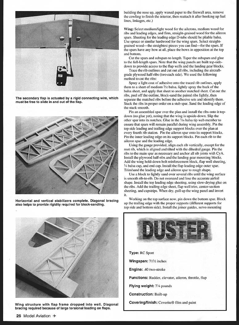
The end-to-end triangulation normally used in lightweight built-up tail surfaces does little to enhance torsional strength. The truss system used on this model provides good resistance to torsional forces because it consists of bilateral triangulation.
#### Vertical stabilizer
- Use very stiff wood for the main fin spar; other wood may be medium/light.
- Pin down the main spar and the forward spar, which are equidistant. Note the forward spar and the leading edge extend through the horizontal stabilizer.
- Install horizontal members and all lower truss diagonals, alternating direction. Install upper truss diagonals, the leading edge, and all ribs.
- Build the rudder abutting the fin and taper edges and tip to profile.
#### Horizontal stabilizer
- This member can be built one side at a time but the two main spars must be continuous.
- Select very firm wood for the rear stabilizer spar and its joiner. Cut both spars to full tip-to-tip length and pin down.
- Add fore and aft members. Notch center members to receive the fin spars before pinning.
- Add the lower level of truss diagonals, alternating direction, then install the upper level, leading edge, and ribs.
- Build the elevator, including the joiner, against the stabilizer. Epoxy the joiner in place. Raise the trailing edge 1/16 inch with shims to match the main spar during assembly.
- After drying/cure, pull up assemblies and block-sand each side smooth. Round edges and tips and taper the rudder and elevator to proper profiles.
Preassembly and Covering
- With the wing mounted and the fuselage sitting on the bench with the tail propped up so that the bottom nose sheeting is in full contact with the bench, fit the horizontal stabilizer to the fuselage and trim/block-sand the seat until the stab sits parallel to the bench. Prefit the fin, using a triangle to check verticality.
- Install all hinges and horns. For a model of this size, Klett-type hinges installed with epoxy are recommended.
- We used Coverite’s 21st Century films with BalsaRite for good adhesion of the film. Coverite spray paints were used for inside the cowling. Follow the manufacturer's directions closely.
- The main ingredient for success and long-lasting film application is to install the film under tension by pulling it and tacking it at many places around a panel. After a panel is covered, do not soften the edges — this will relax the built-in tension.
- Install servos, linkages, and check for free and proper movement of all control surfaces.
- Check the balance point carefully, moving the battery or adding ballast if necessary.
Recommended equipment and components
- Engine: O.S. .40 FX (or similar .40 two-stroke)
- Tank: Great Planes 10-ounce recommended
- Engine mount: Ernst Super Mount 40 (#118) recommended
- Servos: Standard Airtronics servos #94102 recommended
- Radio: Airtronics Module transmitter (configured for flap actuation)
- Covering: Coverite film and paint
Specifications
- Type: RC Sport
- Wingspan: 71.5 inches
- Engine: .40 two-stroke
- Functions: Rudder, elevator, aileron, throttle, flap
- Flying weight: 7.25 pounds
- Construction: Built-up
- Covering/finish: Coverite film and paint
Flying
The basic flight regime of the Duster is comparable to any .40 trainer; transition should present no problem. There is one unusual flight area Duster is capable of: the very low-speed area, where most trainers cannot go.
As flight speed diminishes, aileron authority decreases and rudder becomes more important. Overuse of ailerons in slow turns can lead to undesirable tip-stall; the slower you fly, the more you should use rudder to keep the wings level. If you are not used to using rudder, use coupled aileron-and-rudder for low-speed flight.
Duster has the capability to do standard maneuvers well and it flies inverted. With flaps fully deployed, the Duster will fly very slowly; in a light breeze the model will seem to hover. Because the flaps are positioned ahead of the strip ailerons and close to the aerodynamic center and CG, there is little ballooning with application of flaps. While the flaps add desirable drag to steepen the landing approach and a little extra lift for slower flight, there is no drastic trim change to worry about and stall stability is improved.
If Duster is properly trimmed at cruise and the flaps are deployed, the model will balloon somewhat because of the additional lift. Let the model settle into its new trimmed speed, which will be much slower than cruise. There is no need to retrim when changing speed to compensate for the flaps.
Takeoffs are a bit unusual in that Duster will lift its tail; this is due to the incidence setup. As with any taildragger, use some up elevator for the initial run but let off to avoid taking off prematurely. When you have speed, lift Duster off with a little elevator, or it will take off by itself quickly with flaps half-deployed.
Duster can land shorter than any trainer-type model. With full flaps the approach can be much steeper than normal; the flap does not allow the model to pick up excess speed. While most modern models can take off and climb at a steep angle, Duster can land out of a steep angle. This is a truly balanced STOL-type model.
Aileron and rudder for low-speed flight
- Use more rudder and less aileron as speed decreases to avoid tip-stall.
- Consider coupled aileron-and-rudder for low-speed operations if not comfortable with left-stick rudder.
- Practice slow flight with flaps to learn the model's response; Duster will maintain stability and recover from mild disturbances without abrupt control inputs.
Bill Winter 1912–1998
John Hunton 9154 Rixeyville Rd. Rixeyville, VA 22737
Transcribed from original scans by AI. Minor OCR errors may remain.

