
e-Cobra
Dan Grotzinger
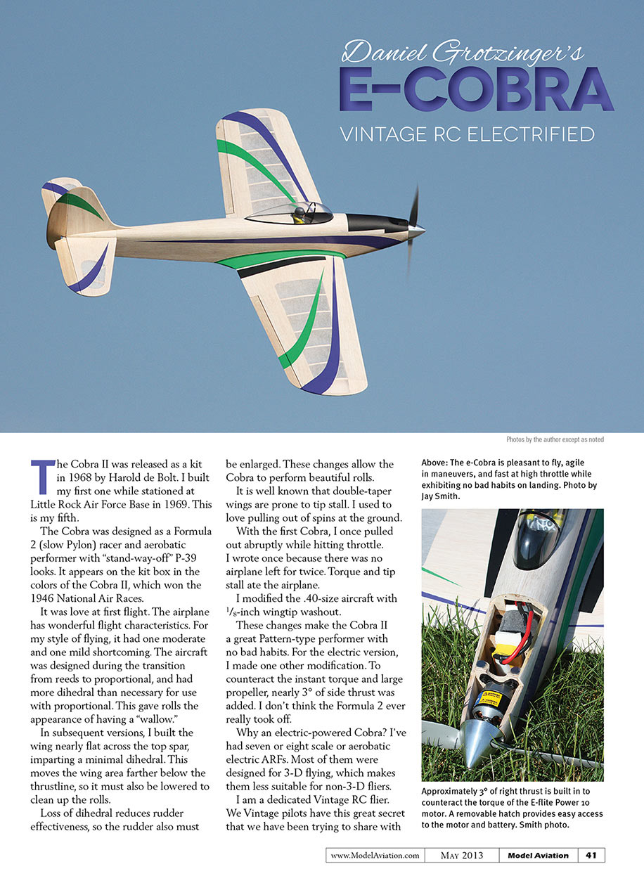
The Cobra II was released as a kit in 1968 by Harold de Bolt. I built my first one while stationed at Little Rock Air Force Base in 1969. This is my fifth.
The Cobra was designed as a Formula 2 (slow Pylon) racer and aerobatic performer with "stand‑way‑off" P-39 looks. It appears on the kit box in the colors of the Cobra II, which won the 1946 National Air Races.
It was love at first flight. The airplane has wonderful flight characteristics. For my style of flying, it had one moderate and one mild shortcoming. The aircraft was designed during the transition from reeds to proportional, and had more dihedral than necessary for use with proportional. This gave rolls the appearance of having a "wallow."
In subsequent versions, I built the wing nearly flat across the top spar, imparting a minimal dihedral. This moves the wing area farther below the thrustline, so it must also be lowered to clean up the rolls.
Loss of dihedral reduces rudder effectiveness, so the rudder also must be enlarged. These changes allow the Cobra to perform beautiful rolls.
It is well known that double‑taper wings are prone to tip stall. I used to love pulling out of spins at the ground. With the first Cobra, I once pulled out abruptly while hitting throttle. I wrote once because there was no airplane left for twice. Torque and tip stall ate the airplane.
I modified the .40‑size aircraft with 1/8‑inch wingtip washout.
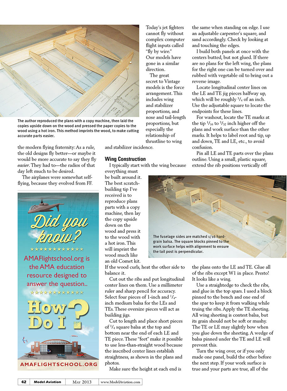
These changes make the Cobra II a great Pattern‑type performer with no bad habits. For the electric version, I made one other modification. To counteract the instant torque and large propeller, nearly 3° of side thrust was added. I don't think the Formula 2 ever really took off.
Why an electric‑powered Cobra? I've had seven or eight scale or aerobatic electric ARFs. Most of them were designed for 3‑D flying, which makes them less suitable for non‑3‑D fliers.
I am a dedicated Vintage RC flier. We Vintage pilots have this great secret that we have been trying to share with the modern flying fraternity: As a rule, the old designs fly better—or maybe it would be more accurate to say they fly easier. They had to—the radios of that day left much to be desired.
The airplanes were somewhat self‑flying, because they evolved from FF.
Today's jet fighters cannot fly without complex computer flight inputs called "fly by wire."
Our models have gone in a similar direction.
The great secret to Vintage models is the force arrangement. This includes wing and stabilizer proportions, and nose and tail‑length proportions, but especially the relationship of thrustline to wing and stabilizer incidence.
Wing Construction
I typically start with the wing because everything must be built around it. The best scratch‑building tip I've received is to reproduce plans parts with a copy machine, then lay the copy upside down on the wood and press it to the wood with a hot iron. This will imprint the wood much like an old Comet kit. If the wood curls, heat the other side to balance it.
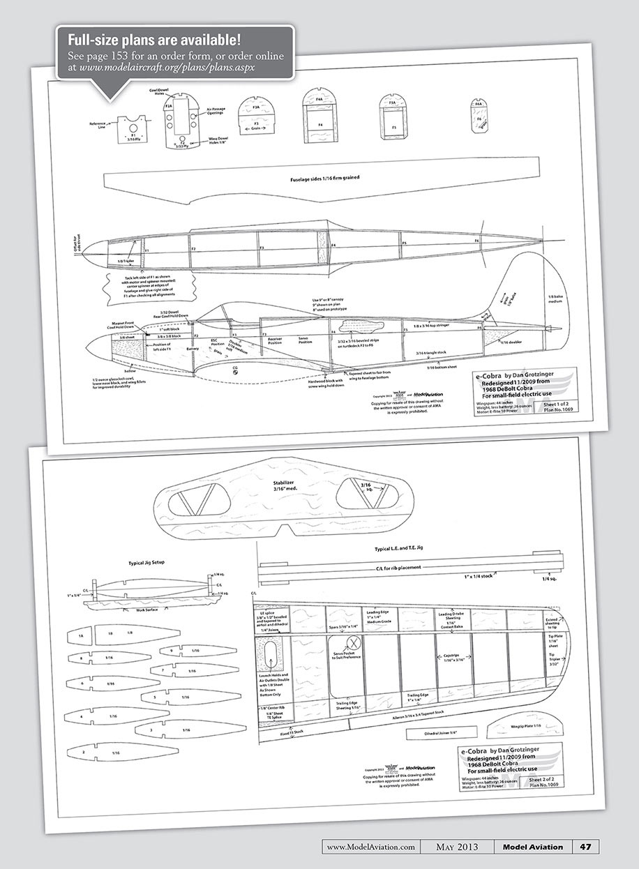
Cut out the ribs and put longitudinal center lines on them. Use a millimeter ruler and sharp pencil for accuracy. Select four pieces of 1‑inch and 1/4‑inch medium balsa for the LEs and TEs. These oversize pieces will act as building jigs.
Cut to length and place short pieces of 1/4 square balsa at the top and bottom near the end of each LE and TE piece. These "feet" make it possible to use less‑than‑straight wood because the inscribed center lines establish straightness, as shown in the plans and photos.
Make sure the height at each end is the same when standing on edge. I use an adjustable carpenter's square, and sand accordingly. Check by looking at and touching the edges.
I build both panels at once with the centers butted, but not glued. If there are no plans for the left wing, the plans for the right one can be turned over and rubbed with vegetable oil to bring out a reverse image.
Locate longitudinal center lines on the LE and TE jig pieces halfway up, which will be roughly 3/4 of an inch. Use the adjustable square to locate the endpoints for these lines.
For washout, locate the TE marks at the tip 1/16 to 3/32 inch higher off the plans and work surface than the other marks. It helps to label root and tip, up and down, TE and LE, etc., to avoid confusion.
Pin all LE and TE parts over the plans outline. Using a small, plastic square, extend the rib positions vertically off the plans onto the LE and TE. Glue all of the ribs except W1 in place. Presto! It looks like a wing.
Use a straightedge to check the ribs, and glue in the top spars. I used a block pinned to the bench and one end of the spar to keep it from walking while truing the ribs. Apply the TE sheeting. All wing sheeting is contest balsa, but its grain should not be soft or mushy. The TE or LE may slightly bow when you glue down the sheeting. A wedge of balsa pinned under the TE and LE will prevent this.
Turn the wing over, or if you only made one panel, build the other before the next step. If your work surface is true and your parts are true, all of the 1/4 square balsa feet on the LE and TE jigs should touch the work surface with little or no pressure.
The sheeting may create a slight warping tension. This can be corrected with the remaining sheeting. If you release the pins and a foot comes up from tension, that same distortion should show up in reverse upside down. That can be built out. If your wing lays flat one way but not the other, there is a flaw in your parts or the work surface is not flat. Find the problem and correct it.
After pinning the wing upside down, add the bottom spars (now at the top), again truing the ribs and using a block to ensure the ribs are 90° upright. Add the TE sheeting, then the LE sheeting. I used one‑hour epoxy on the ribs.
The front edge of the LE sheeting is beveled to the LE so there will be no gap when you sand away material in the final shaping. A fine line of CA can be used. Too much glue makes shaping difficult. More glue can be added later to increase the bond.
The sheeting is glued to the spar with CA. I leave some spar exposed for a better bond for the capstrips. This makes it easy to run a line of CA under the sheeting. Add the capstrips, remove the panels from the plans, and trim the spars and sheeting flush so that the wingtip plates can be installed.
Tack a diagonal strip over the wing surface to prevent distortion and misalignment while you bevel the wing roots for dihedral and join them. Tape 80‑grit sandpaper to your workbench and tape the end of the bottom (true bottom) spar to avoid sanding material from it. (The bottom spar is the longest point in a wing with dihedral.)
Everything else must be shorter, if only slightly. Stand the wing on its end and move it back and forth, front to rear, to bevel the wing root. Your sanding block is stable and you should have two hands firmly on the wing for precise control. You can stand the wing on its root and see how much dihedral you have.
Do both panels the same way, but don’t lean too hard on a LE or TE or you may create wing sweep. If you do, place the short part off the sandpaper so that only the long part is being sanded, and you can make a correction. With some care you can make a perfectly fitting root joint.
Glue the wings together. CA should work because of the precise fit. Shape, fit, and install all dihedral joiners after the wing halves have been joined. This is easier and more accurate than gluing them into one panel and then trying to fit everything to the other side.
Upside down, my wing had enough dihedral to allow 1/8 inch between the wing center and work surface. Based on flight tests, I might be tempted to bring that measurement to 1/4 inch on the next Cobra.
Locate and create your servo pockets, then sheet the bottom center sections. Join all sheeting at the center—including the LE and TE sheeting—with fiberglass tape from the inside. Trim W1 as needed to clear the glass cloth splice, and glue into place.
Pin down either wing panel and install the LE sheeting, center sheeting, and capstrips. Allow for servo wire access and airflow outlets. Unpin this side, pin down the remaining panel, and repeat.
W1 may be relieved for short sheeting splices at the center line because it is now impossible to get access for glass cloth, or you can use glass cloth for the top on the outside.
Now complete the wingtip and beveled TE center section. The excess LE and TE material can be shaved off, and the entire wing can be sanded to the finished airfoil shape.
This will take time but is worth the extra effort. You may need to bevel your ailerons from larger stock. I couldn't find this size in the hobby shops.
Fuselage Construction
The fuselage sides are matched 1/16 hard‑grain balsa. Hard grain doesn't have to mean heavy! Some wood is firm without being heavy.
Cut one side using the hot‑iron imprint method and then pin it to the second piece, using it for a template. The doublers can be scrap material placed crossgrain at the angle shown on the plans, working forward from the line shown. It is then trimmed to the fuselage's side outline.
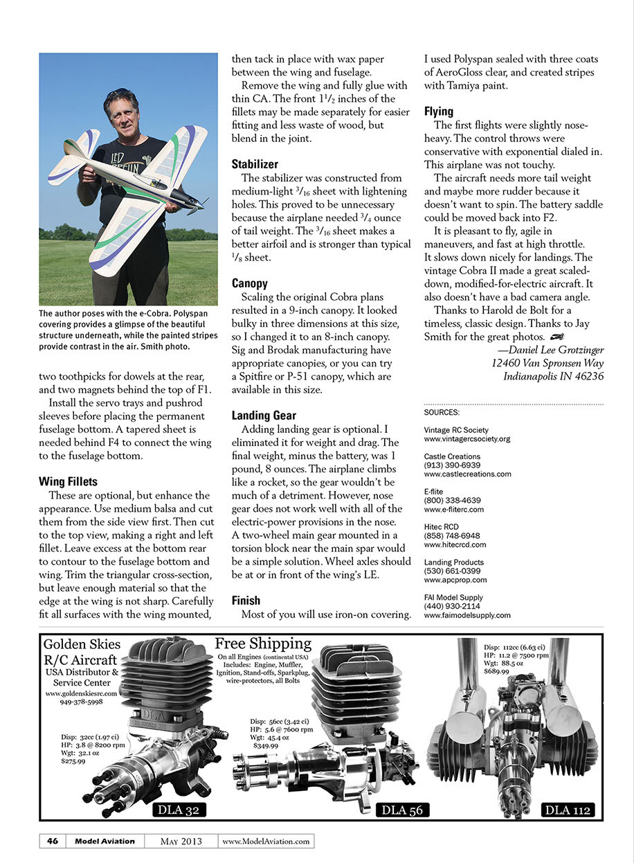
Transfer the bulkhead positions to the completed right and left sides as needed from the plans or from the imprinted side. Cut and fabricate all of the bulkheads. Pin all of the bulkheads except F1 upside down on the top view of the plans.
Carefully place one fuselage side upside down and pin it to the plans and bulkheads using the lines for positioning. Glue with CA while checking for the square and alignment. Repeat for the second side and join the tail last.
A square block pinned to the work surface will help with alignment and ensure that the tail post is perpendicular. Tack a temporary bottom on the fuselage, including some cross grain in the wing saddle area. This will ensure proper alignment while installing F1 and the turtledeck.
Add tops to all bulkheads and the center longeron or stringer. Attach the motor with spinner to F1, and tack F1 to the left fuselage side so that the spinner clears the front. The size of your motor will determine where F1 is positioned. Make sure it is perpendicular to the top of the fuselage side.
The sides are pulled together and the right side of F1 will be roughly 1/8 inch rearward so that the spinner is centered between the fuselage sides. (The right side must be shortened to clear the spinner.)
Review the plans to ensure that you have not pulled the sides off center. When everything is correct, tack the right side of F1. When you are satisfied, finish gluing with thin CA, followed by epoxy. The side thrust is now built in. If you wish to have a cockpit, place the floor now.
This fuselage has no lightening holes, but it has airflow passages through the cowl blocks, bulkheads, and wing sheeting. The airplane will not fall apart on a rough landing.
I sheeted the turtledeck with beveled 3/32 x 3/16‑inch strips. They are easy to cut from sheet with a metal straightedge, holding the knife at an angle for the bevel. Practice with a few pieces and you will see it is easy to find the bevel angle that yields a tight seam.
Toward the tail, the bevel must increase because of the smaller bulkhead radius. Sand in the correction. You can also taper the strips to accommodate the geometry. They may be 1/4‑inch wide at the front and 3/16‑inch wide at the tail. Place the strips alternately right and left—meeting at the top with a dovetail at the rear end.
I use Testors wood cement for the long seams, but CA to bond the strips to the bulkheads. Testors makes sanding easy. CA would make this work difficult.
This turtledeck is strong, light, and introduces no stresses or warping. When sanded, it will be approximately 3/64‑inch thick, yet strong. The original de Bolt kits used wetted balsa sheets. You may wish to use stringers and fabric covering, or even a solid block hollowed after shaping.
The nose gets 1/8‑inch triplers. Relieve the left side at the rear to clear the motor mount. Now is a good time to build the battery saddle. It is roughly 1 3/8 inches wide, which leaves much of the battery exposed to the air. F2 shows an opening that must be sized to your batteries.
The sides are 1/32 plywood glued inside the F2 opening. The floor is 3/16 hard balsa to create a gluing surface. Tie the front of the saddle to the fuselage sides with 1/4 balsa with air holes through it.
My saddle has thin, rubber padding. Install the Velcro straps before closing up the bottom block. Glue 3/8‑inch square blocks to the top of the sides between F1 and F2. This accommodates shaping the nose and is stronger than having the cowl down the sides.
Add the bottom nose block as soon as the wing is accurately positioned and holes are drilled through F2, from the front into the wing's LE, for the dowels. Tack this block, shape it, and then remove and hollow it for airflow before permanently gluing. This block will need a groove to get your Allen driver to the mounting bolts. I did not use the lower left mounting bolt because of poor access on that side.
A 3/8 sheet is placed over the motor for the front lower cowl. It will need to be trimmed to fit the motor. Pin it firmly in place. (The rear edge will follow the side‑thrust angle of F1.) Pin the larger cowl block over the 3/8‑inch nose sheet and 3/8‑inch square battery compartment blocks, gluing only to the front cowl sheet with Testors. Let it dry overnight, then remove it to check the fit.
If the fit is good, tack it down with four small dots of glue and sand the entire nose to the spinner. When satisfied, carefully release and hollow for airflow and shape the air inlet over the motor to suit. The cowl is attached with then tack in place with wax paper between the wing and fuselage.
Remove the wing and fully glue with thin CA. The front 1½ inches of the fillets may be made separately for easier fitting and less waste of wood, but blend in the joint.
Stabilizer
The stabilizer was constructed from medium‑light 3/16 sheet with lightening holes. This proved to be unnecessary because the airplane needed 3/4 ounce of tail weight. The 3/16 sheet makes a better airfoil and is stronger than typical 1/8 sheet.
Canopy
Scaling the original Cobra plans resulted in a 9‑inch canopy. It looked bulky in three dimensions at this size, so I changed it to an 8‑inch canopy. Sig and Brodak manufacturing have appropriate canopies, or you can try a Spitfire or P‑51 canopy, which are available in this size.
Landing Gear
Adding landing gear is optional. I eliminated it for weight and drag. The final weight, minus the battery, was 1 pound, 8 ounces. The airplane climbs like a rocket, so the gear wouldn’t be much of a detriment. However, nose gear does not work well with all of the electric‑power provisions in the nose. A two‑wheel main gear mounted in a torsion block near the main spar would be a simple solution. Wheel axles should be at or in front of the wing’s LE.
Finish
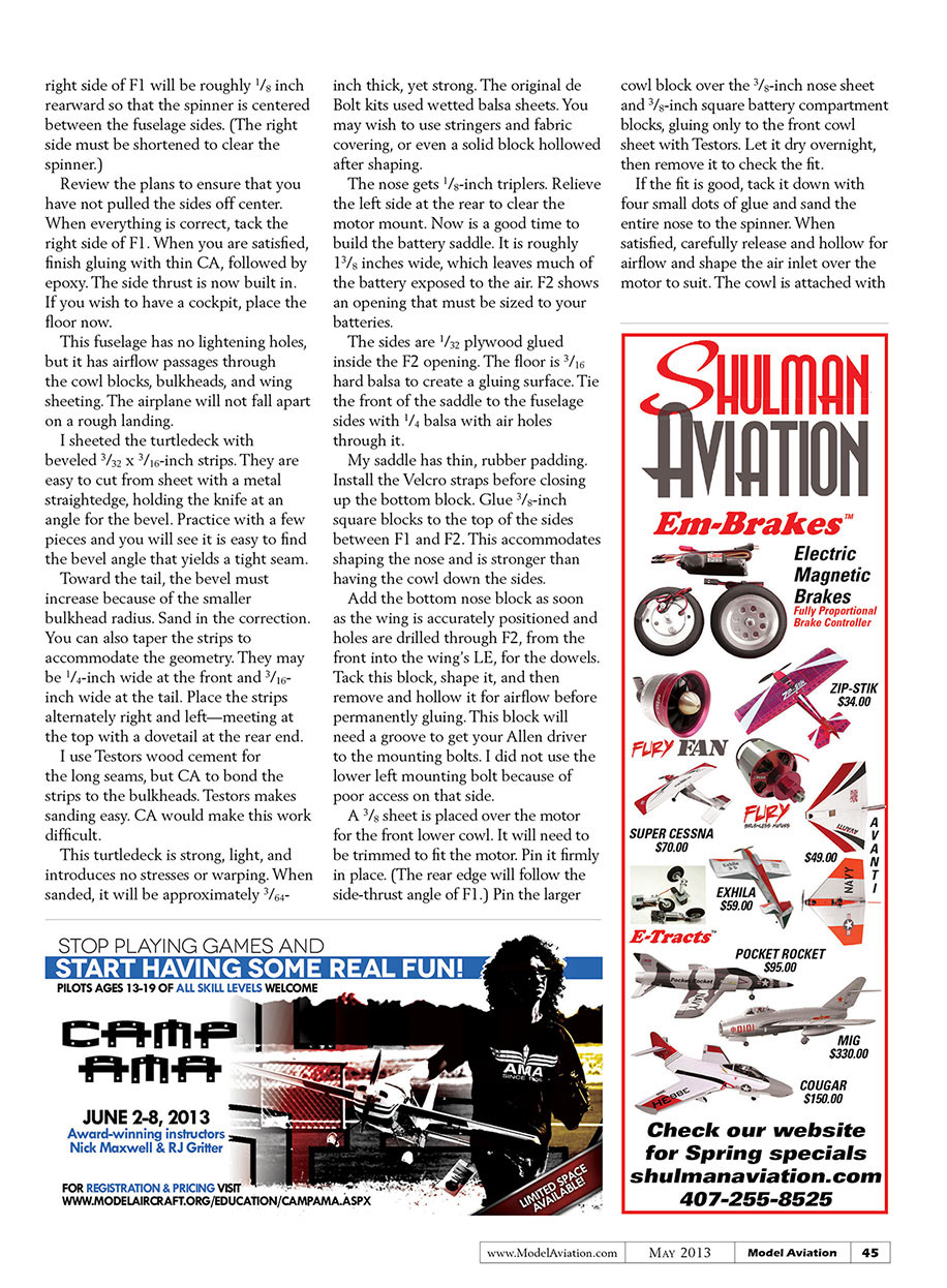
Most of you will use iron‑on covering. I used Polyspan sealed with three coats of AeroGloss clear, and created stripes with Tamiya paint.
Flying
The first flights were slightly nose‑heavy. The control throws were conservative with exponential dialed in. This airplane was not touchy.
The aircraft needs more tail weight and maybe more rudder because it doesn’t want to spin. The battery saddle could be moved back into F2.
It is pleasant to fly, agile in maneuvers, and fast at high throttle. It slows down nicely for landings. The vintage Cobra II made a great scaled‑down, modified‑for‑electric aircraft. It also doesn’t have a bad camera angle.
Thanks to Harold de Bolt for a timeless, classic design. Thanks to Jay Smith for the great photos.
—Daniel Lee Grotzinger 12460 Van Spronsen Way Indianapolis IN 46236
SOURCES:
Vintage RC Society www.vintagercsociety.org
Castle Creations (913) 390-6939 www.castlecreations.com
E-flite (800) 338-4639 www.e-flite.com
Hitec RCD (858) 748-6948 www.hitecrcd.com
Landing Products (530) 661-0399 www.apcprop.com
Fai Model Supply (440) 930-2114 www.faimodelsupply.com
e-Cobra
Dan Grotzinger
e-Cobra by Dan Grotzinger Redesigned 11/2009 from 1968 DeBolt Cobra For small-field electric use Wingspan: 44 inches Weight less battery: 26 ounces Sheet 1 of 2 Plan No. 1069
e-Cobra by Dan Grotzinger Redesigned 11/2009 from 1968 DeBolt Cobra For small-field electric use Wingspan: 44 inches Weight less battery: 26 ounces Sheet 2 of 2 Plan No. 1069
Transcribed from original scans by AI. Minor OCR errors may remain.

