
The E-Soaring Advantage
BY LEE ESTINGOY
The latest power systems make Soaring a breeze
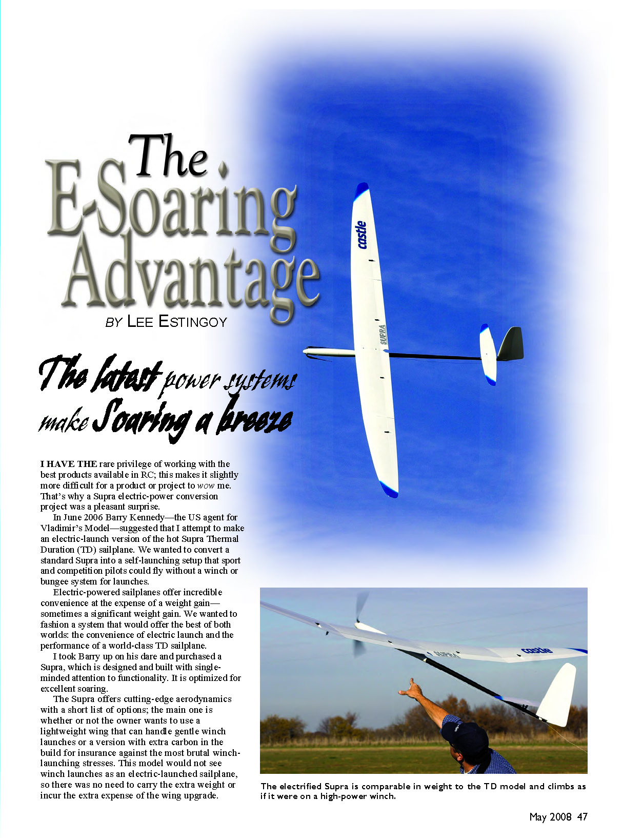
I have the rare privilege of working with the best products available in RC; this makes it slightly more difficult for a product or project to wow me. That's why a Supra electric-power conversion project was a pleasant surprise.
In June 2006 Barry Kennedy—the U.S. agent for Vladimir Model—suggested that I attempt to make an electric-launch version of the hot Supra Thermal Duration (TD) sailplane. We wanted to convert a standard Supra into a self-launching setup that sport and competition pilots could fly without a winch or bungee system for launches.
Electric-powered sailplanes offer incredible convenience at the expense of a weight gain—sometimes a significant weight gain. We wanted to fashion a system that would offer the best of both worlds: the convenience of electric launch and the performance of a world-class TD sailplane.
I took Barry up on his dare and purchased a Supra, which is designed and built with single-minded attention to functionality. It is optimized for excellent soaring.
The Supra offers cutting-edge aerodynamics with a short list of options; the main one is whether or not the owner wants a lightweight wing that can handle gentle winch launches or a version with extra carbon in the build for insurance against the most brutal winch-launching stresses. This model would not see winch launches as an electric-launched sailplane, so there was no need to carry the extra weight or incur the extra expense of the wing upgrade.
Where to Begin With Electric Power Systems?
I generally select components for a power system by determining the amount of power I need to achieve the performance I expect from the project. An electric system's power is expressed in terms of watts (746 watts = 1 horsepower). A total of 100 watts per pound is good for brisk climbs for sailplanes.
I estimated the airframe and equipment would weigh about 75 ounces, or roughly 4.5 pounds. That leads to a conclusion that more than 450 watts would be needed.
I wanted to use a two-cell pack to meet electric-competition rules; I knew I needed to achieve no less than a 65-amp draw (450 watts ÷ 7 volts ≈ 65 A). "Good climb" is never enough for sailplane fliers, so let's say I needed 70–100 amps on 2S. That meant finding two cells in the 2500–5000 mAh range. Given a C rating of approximately 20, I needed a baseline capacity of 3500–5000 mAh cells. If the C rating were higher, say 30C, the required capacity would shrink to about 2500 mAh.
Finding the cells was convenient because I have TanicPacks nearby and could try sizes until one fit. I settled on a 4200 mAh 2S pack. It is capable of putting out more than 80 amps for a sailplane.
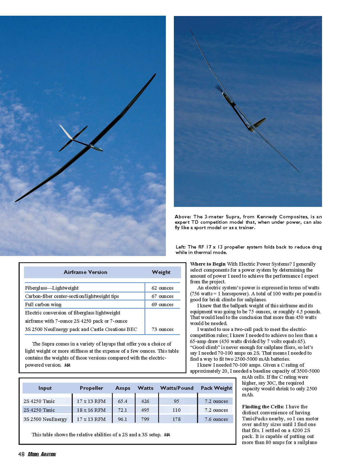
Airframe versions and weights
- Fiberglass — Lightweight: 62 ounces
- Carbon-fiber center-section / lightweight tips: 67 ounces
- Full carbon wing: 69 ounces
- Electric conversion of fiberglass lightweight airframe (with 7-ounce 2S 4250 pack or 7-ounce 3S 2500 NeuEnergy pack and Castle Creations BEC): 73 ounces
Input and performance comparisons
- 2S 4250 Tanic, 17 x 13 RFM prop: 65.4 A, 426 W, 95 W/lb, pack weight 7.2 oz
- 2S 4250 Tanic, 18 x 16 RFM prop: 72.1 A, 495 W, 110 W/lb, pack weight 7.2 oz
- 3S 2500 NeuEnergy, 17 x 13 RFM prop: 96.1 A, 799 W, 178 W/lb, pack weight 7.6 oz
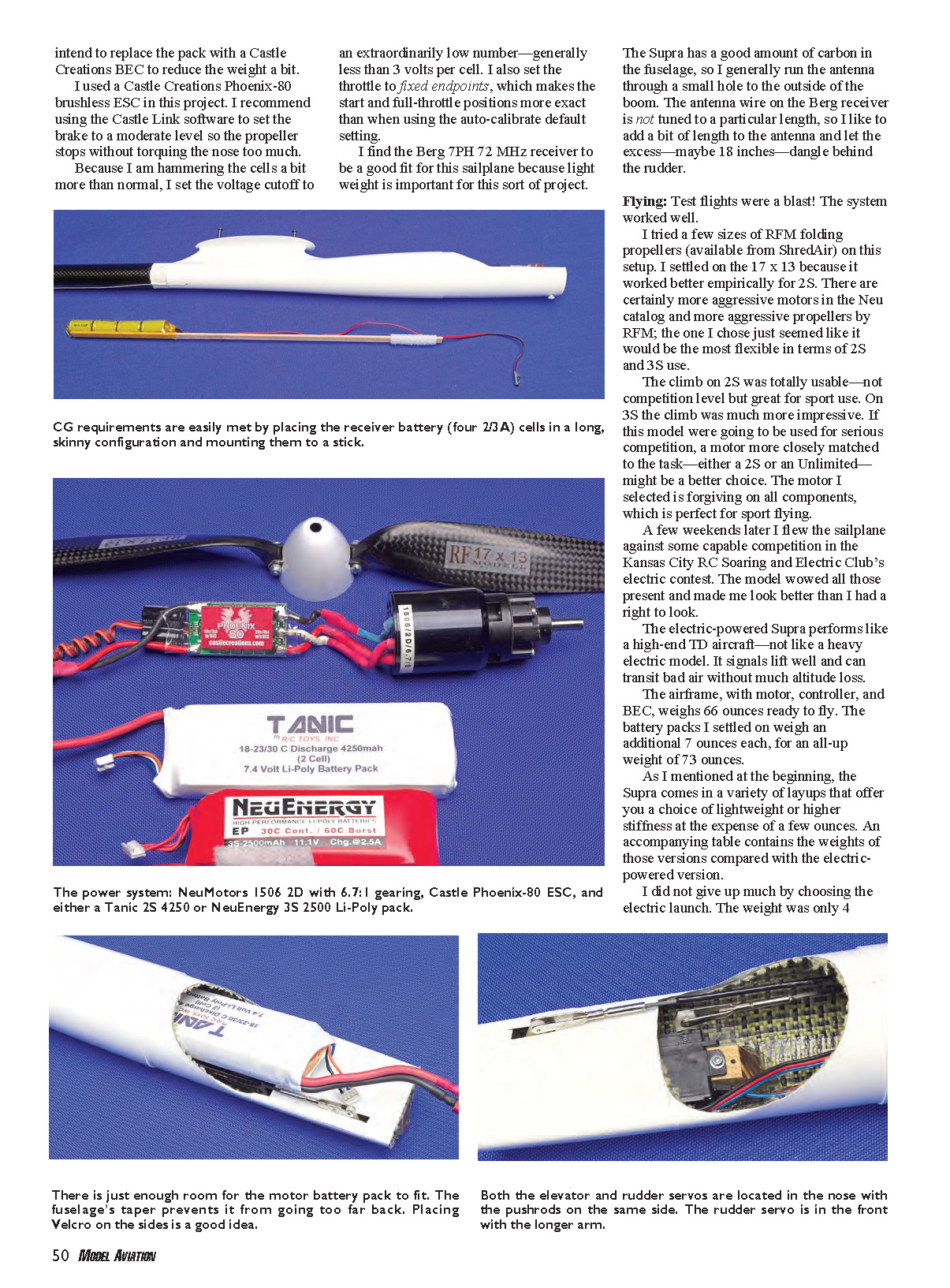
Spending time on Steve Neu's website revealed that I needed a 1406 2D motor with a 6.7:1 gear ratio to give the best performance for the given volts and amps. This motor also works well if stepping up to a 3S Li-Po pack.
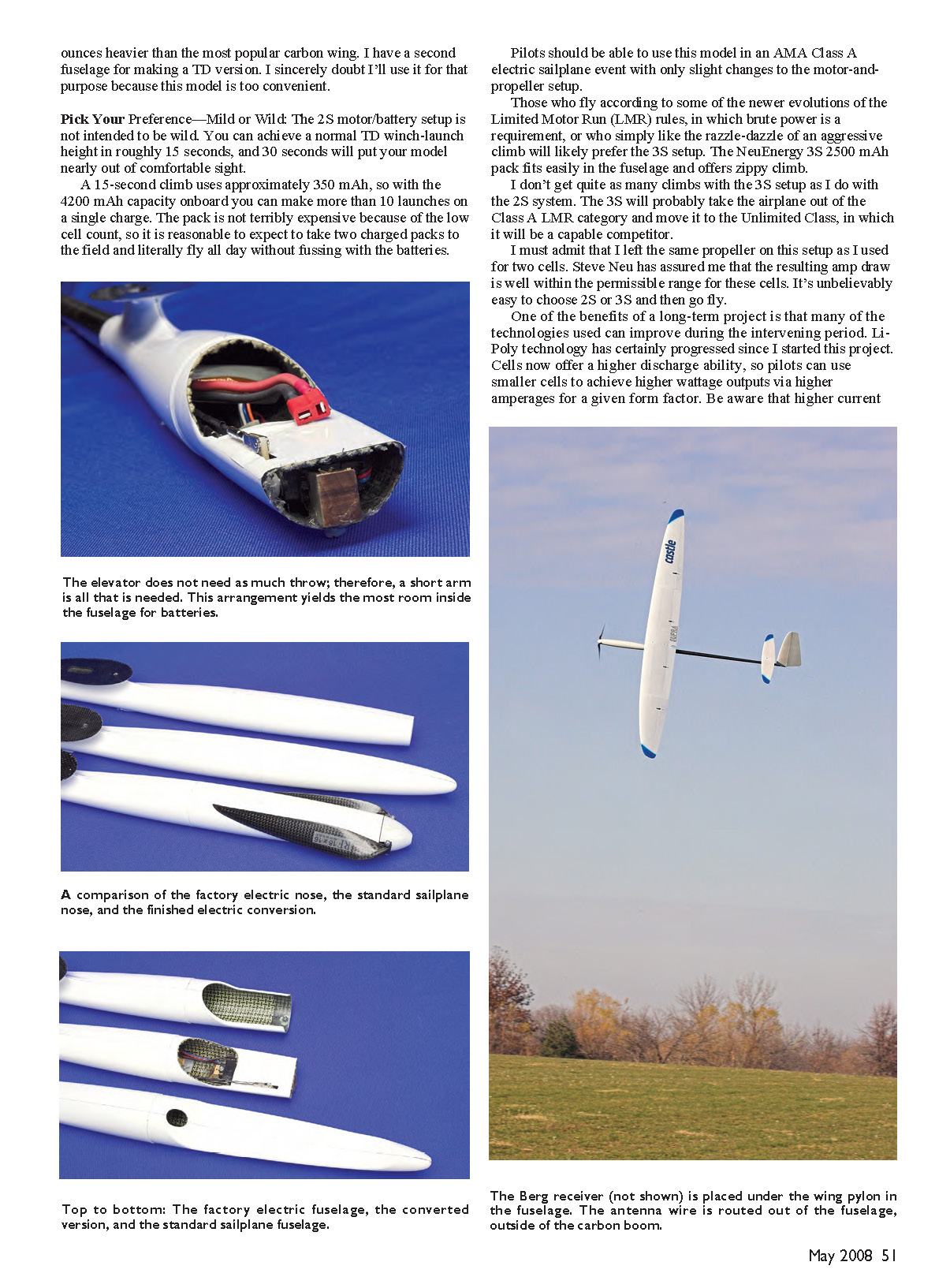
A bit of "basement flying" with the pieces taped to the airframe to check the CG convinced me that the usual layout of the elevator and/or rudder servos in the tail would result in an extremely tail-heavy airplane. The servos needed to be placed in the nose to maintain effective balance. I didn't want to cut up the vertical stabilizer or make a subfin for the servos, so this was good news.
I shortened the inner nose to allow clearance for the motor and spinner, which are mounted on the outer nose cone. The remaining stub section was still sturdy because it was a complete tube-in cross-section; I kept that deck intact to support the outer nose cone.
Although the standard method for mounting servos in this fuselage is in the top of the deck, I laid them on their sides and placed them under the small deck normally used for servo mounting to provide room for battery removal. Putting both servo pushrods on the same side of the sailplane gave the largest usable space for the cells inside the fuselage.
I used a longer servo arm on the rudder servo and placed it in the front position so the pushrod would clear the elevator servo arm by passing over the top of the other servo arm.
The airframe plans suggest affixing the pushrods to the outside of the tailboom. I chose to place them inside the fuselage; I couldn't bear for such a beautiful airplane to have its internals exposed.
The bulkhead at the front of the larger fuselage section needed to be opened to accommodate the batteries. I started small and ended up with as large an opening as possible. A 2.5-inch rotary sanding drum made this a tidy procedure.
I left as much of the front of the inner fuselage as possible because the nose cone is not designed to be a structural member and benefits from internal support. I used a small block of wood to support the front servo and accept the nose-cone support screw.
After assembly, I checked the CG. The Supra was a bit nose-heavy, but electric flight components offer a great deal of flexibility in these situations.
I elected to use 2/3A cells for the receiver pack. I mounted them on a stick and slid them into the proper position in the pod to achieve the balance I needed. I placed Velcro on the front of the stick and in the fuselage to secure the receiver pack. I intend to replace this pack with a Castle Creations BEC to reduce weight.
I used a Castle Creations Phoenix-80 brushless ESC in this project. I recommend using the Castle Link software to set the brake to a moderate level so the propeller stops without torquing the nose too much.
Because I am stressing the cells more than normal, I set the voltage cutoff low—generally less than 3 volts per cell. I also set the throttle to fixed endpoints, which makes the start and full-throttle positions more exact than when using the auto-calibrate default setting.
I find the Berg 7PH 72 MHz receiver is a good fit because light weight is important for this sort of project.
The Supra has a good amount of carbon in the fuselage, so I generally run the antenna through a small hole to the outside of the boom. The antenna wire on the Berg receiver is not tuned to a particular length, so I like to add a bit of length and let the excess (maybe 18 inches) dangle behind the rudder.
Flying
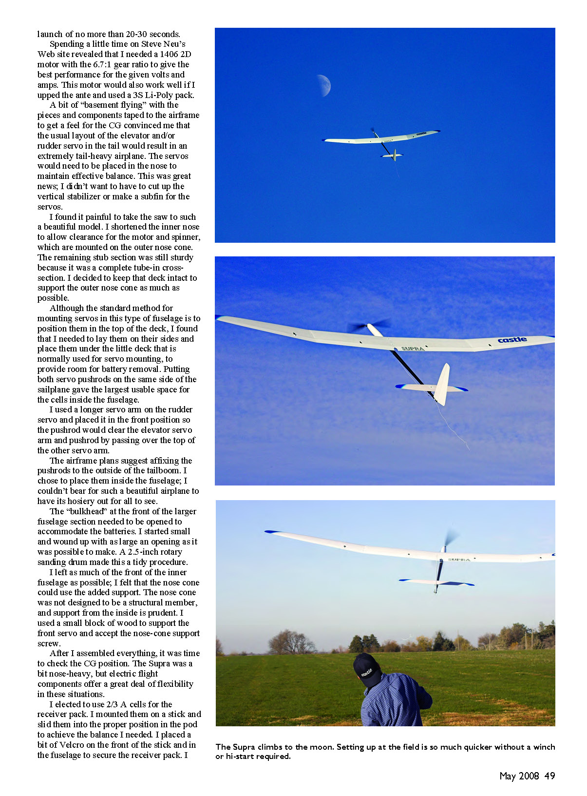
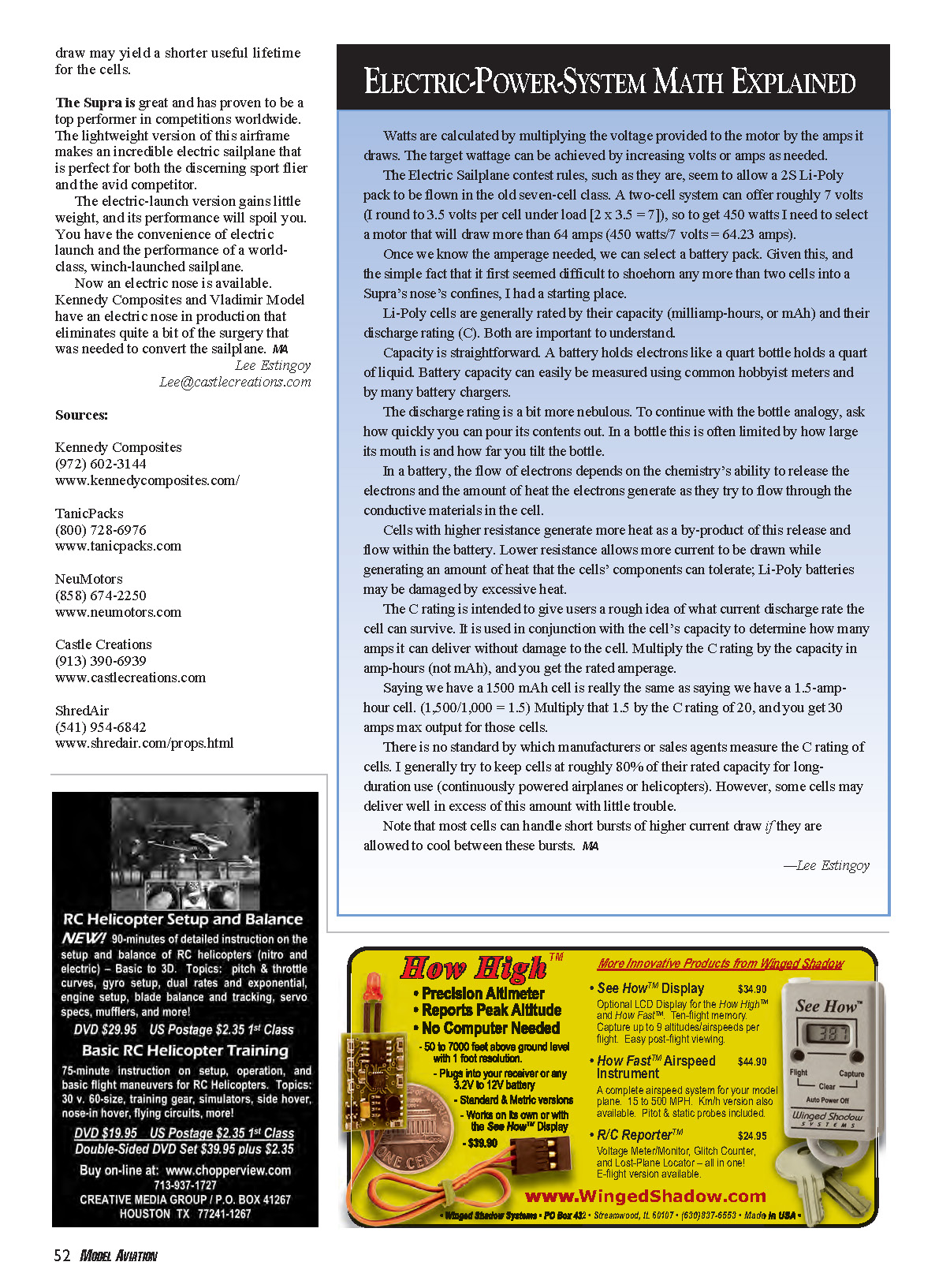
Test flights were a blast—the system worked well.
I tried a few sizes of RFM folding propellers (available from ShredAir). I settled on the 17 x 13 because it worked best empirically for 2S. There are certainly more aggressive motors in the Neu catalog and more aggressive props by RFM; the one I chose seemed the most flexible for both 2S and 3S use.
The climb on 2S was totally usable—not competition level but great for sport use. On 3S the climb was much more impressive. If this model were to be used for serious competition, a motor more closely matched to the task—either a specifically optimized 2S motor or an Unlimited setup—might be a better choice. The motor I selected is forgiving on all components, which is perfect for sport flying.
A few weekends later I flew the sailplane against capable competition in the Kansas City RC Soaring and Electric Club's electric contest. The model wowed those present and made me look better than I had a right to look.
The electric-powered Supra performs like a high-end TD aircraft—not like a heavy electric model. It signals lift well and can transit bad air without much altitude loss.
The airframe, with motor, controller, and BEC, weighs 66 ounces ready to fly. The battery packs I settled on weigh an additional 7 ounces each, for an all-up weight of 73 ounces.
I did not give up much by choosing the electric launch. The weight was only 4 ounces heavier than the most popular carbon-wing version. I have a second fuselage for making a TD version, but I sincerely doubt I'll use it for that purpose because this model is too convenient.
Pick Your Preference — Mild or Wild
- 2S setup:
- The 2S motor/battery setup is not intended to be wild. You can achieve a normal TD winch-launch height in roughly 15 seconds, and 30 seconds will put your model nearly out of comfortable sight.
- A 15-second climb uses approximately 350 mAh, so with a 4200 mAh pack you can make more than 10 launches on a single charge.
- The pack is not terribly expensive because of the low cell count; taking two charged packs to the field makes it reasonable to fly all day without fussing with batteries.
- Pilots should be able to use this model in an AMA Class A electric sailplane event with only slight changes to motor and prop.
- 3S setup:
- Those who fly under newer Limited Motor Run (LMR) rules that favor brute power, or who like an aggressive climb, will prefer the 3S setup.
- The NeuEnergy 3S 2500 mAh pack fits easily in the fuselage and offers a zippy climb, though you won't get as many climbs per charge as with the 2S system.
- The 3S probably moves the airplane from Class A/Limited into the Unlimited Class for competition, where it will be a capable competitor.
I left the same propeller on for both 2S and 3S. Steve Neu assured me the resulting amp draw is within the permissible range for the cells. It's unbelievably easy to choose 2S or 3S and then go fly.
Li-Poly technology has progressed since I started this project. Cells now offer higher discharge ability, so pilots can use smaller cells to achieve higher wattage outputs via higher amperages for a given form factor. Be aware that higher current draw may shorten cell lifetime.
The Supra is a top performer in competitions worldwide. The lightweight version of this airframe makes an incredible electric sailplane perfect for both the discerning sport flier and the avid competitor.
The electric-launch version gains little weight and its performance will spoil you. You get the convenience of electric launch and the performance of a world-class, winch-launched sailplane.
Now an electric nose is available. Kennedy Composites and Vladimir Model have an electric nose in production that eliminates quite a bit of the surgery that was needed to convert the sailplane.
Lee Estingoy [email protected]
Sources
- Kennedy Composites — (972) 602-3144 — www.kennedycomposites.com
- TanicPacks — (800) 728-6976 — www.tanicpacks.com
- NeuMotors — (858) 674-2250 — www.neumotors.com
- Castle Creations — (913) 390-6939 — www.castlecreations.com
- ShredAir — (541) 954-6842 — www.shredair.com/props.html
ELECTRIC-POWER-SYSTEM MATH EXPLAINED
Watts are calculated by multiplying the voltage provided to the motor by the amps it draws. The target wattage can be achieved by increasing volts or amps as needed.
Electric sailplane contest rules often allow a 2S Li-Poly pack to be flown in the old seven-cell class. A two-cell system offers roughly 7 volts (I round to 3.5 volts per cell under load: 2 × 3.5 = 7). To get 450 watts you need a motor that will draw more than about 64 amps (450 W ÷ 7 V ≈ 64.2 A).
Once we know the amperage needed, we can select a battery pack. Given the difficulty of shoehorning more than two cells into a Supra's nose, that provided a practical starting place.
Li-Poly cells are generally rated by capacity (milliamp-hours, or mAh) and discharge rating (C). Both matter.
- Capacity: Like a bottle's volume. A 1500 mAh cell = 1.5 amp-hours.
- C rating: Like how fast you can pour the bottle. Multiply the C rating by the capacity in amp-hours to get the rated amperage. For example, a 1500 mAh (1.5 Ah) cell at 20C can deliver 1.5 × 20 = 30 A.
C ratings are not standardized across manufacturers. I generally try to use cells at roughly 80% of their rated capacity for long-duration use (continuous power). Some cells can deliver more with little trouble, and most can handle short bursts of higher current if allowed to cool between bursts.
Be aware that higher current draw increases heat and may shorten cell life. —Lee Estingoy
Transcribed from original scans by AI. Minor OCR errors may remain.

