
Bob Gialdini's ECLIPSE
A ’60s thoroughbred revisited
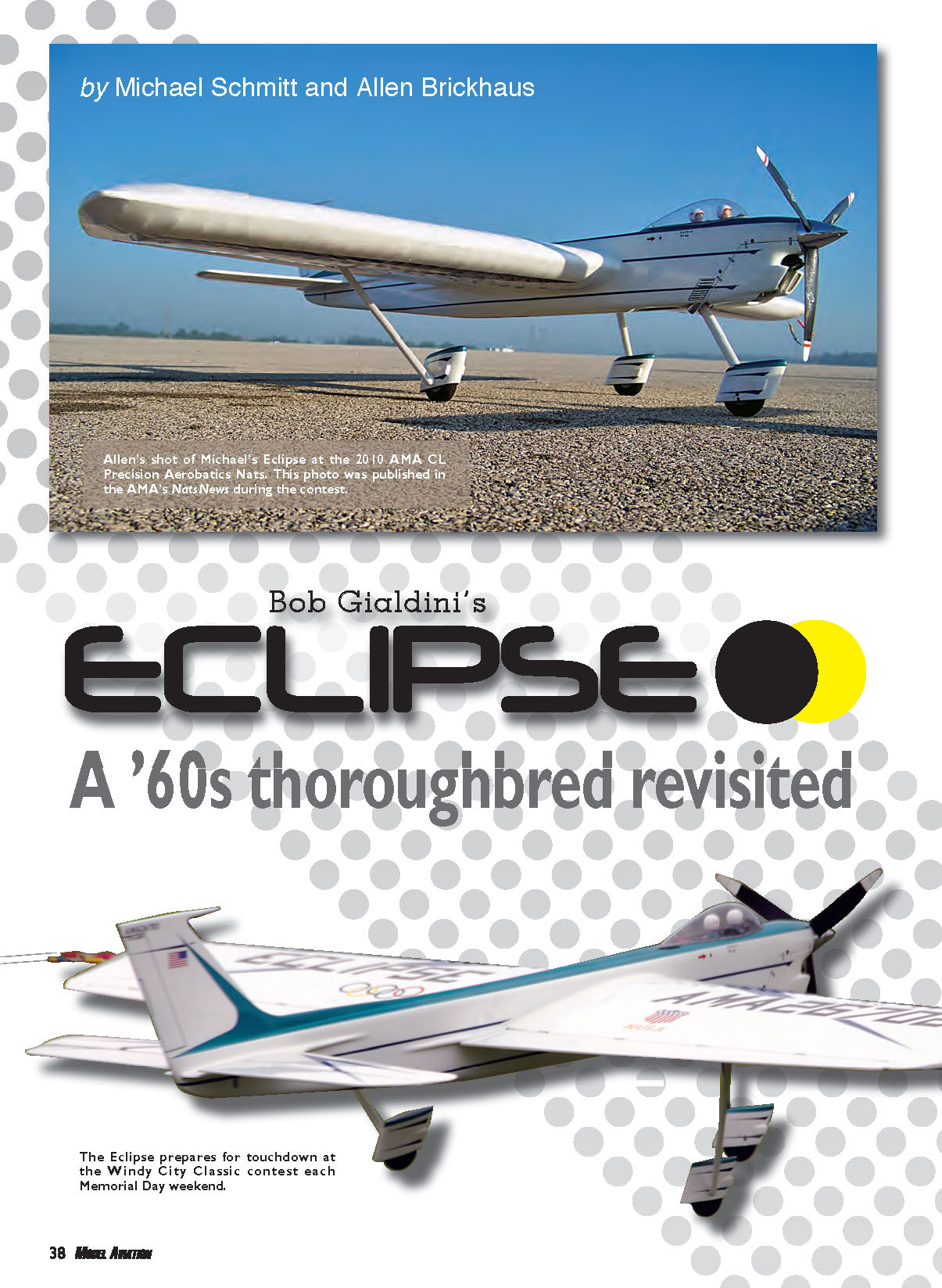
by Michael Schmitt and Allen Brickhaus
BOB GIALDINI'S ECLIPSE was the first Precision Aerobatics (CL Stunt) model to win the AMA Nats with a muffler installed. The history of Bob and the family tree of the Sting Ray and Rayette was highlighted in the February, March, May, and June 2007 issues of Flying Models magazine.
Those CL Stunt columns were composed to encourage builders to look at FM and other plans services as excellent sources of great Classic-legal stunters. Look through older but early 2007 Flying Models issues for more basic background information about Bob and his models.
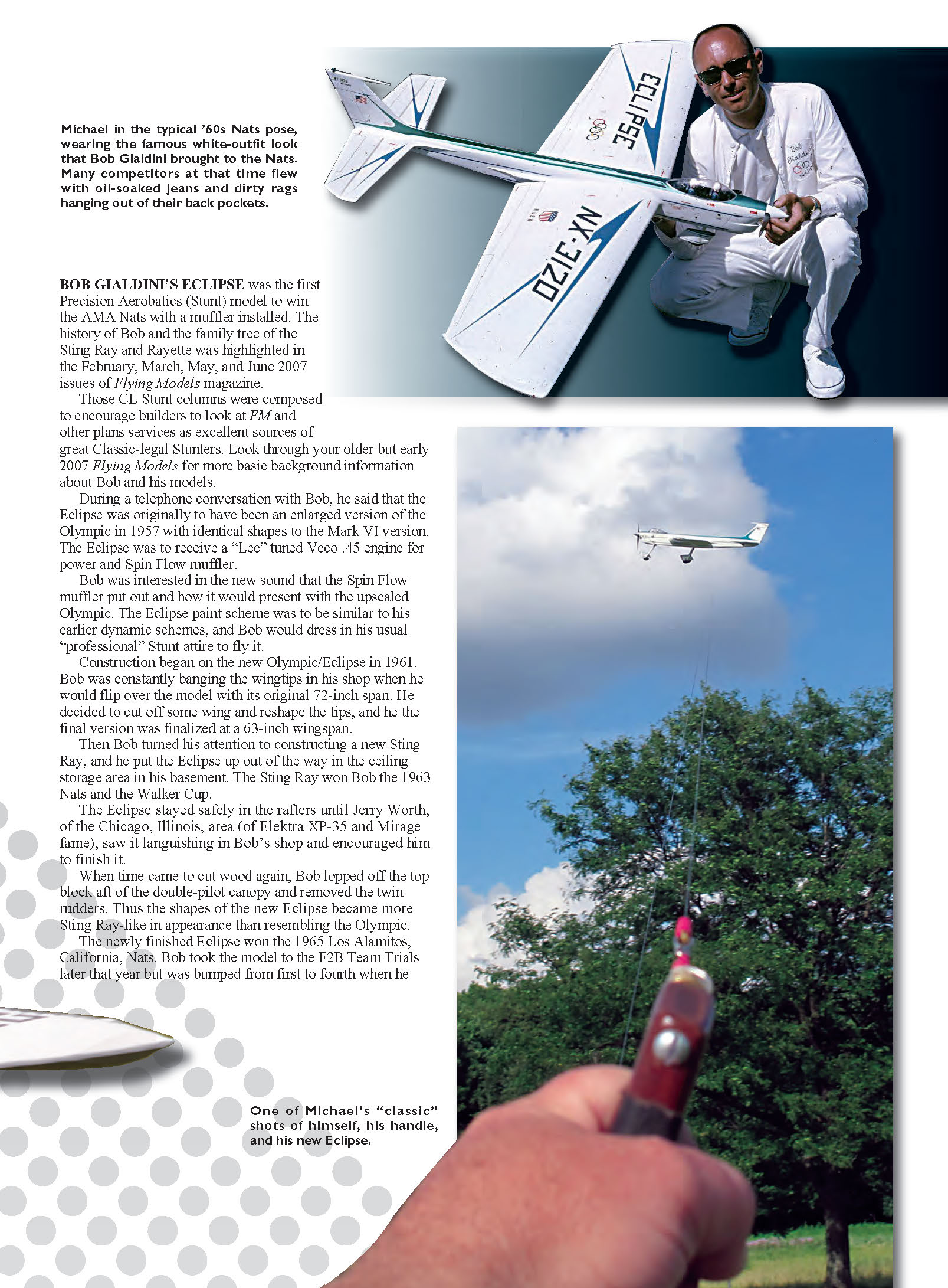
During a telephone conversation with Bob, he said that the Eclipse was originally to have been an enlarged version of the Olympic in 1957 with shapes identical to the Mark VI version. The Eclipse was to receive a "Lee" tuned Veco .45 engine for power and a Spin Flow muffler. Bob was interested in the new sound the Spin Flow muffler produced and how it would present with the upscaled Olympic. The Eclipse paint scheme was to be similar to his earlier dynamic schemes, and Bob would dress in his usual "professional" Stunt attire to fly it.
Construction began on the new Olympic/Eclipse in 1961. Bob was constantly banging the wingtips in his shop when he would flip over the model with its original 72-inch span. He decided to cut off some wing and reshape the tips; the final version settled at a 63-inch wingspan.
Then Bob turned his attention to constructing a new Sting Ray, and he put the Eclipse up out of the way in the ceiling storage area in his basement. The Sting Ray won Bob the 1963 Nats and the Walker Cup. The Eclipse stayed safely in the rafters until Jerry Worth (of Electra XP-35 and Mirage fame) saw it languishing in Bob's shop and encouraged him to finish it.
When time came to cut wood again, Bob removed the top block aft of the double-pilot canopy and deleted the twin rudders. Thus the shapes of the new Eclipse became more Sting Ray–like in appearance than resembling the Olympic.
The newly finished Eclipse won the 1965 Los Alamitos, California, Nats. Bob took the model to the F2B Team Trials later that year but was bumped from first to fourth when he deleted the triangles from an otherwise well-flown pattern. Bob then decided to "give back" to the hobby by becoming a judge. He served extremely well as a local, Nats, and international FAI judging staff member.
The Eclipse was a giant among stunters at the time, in the same size category as the original Sharks that Lew McFarland was flying. Lew was retired from the US Air Force during this period and was working as a pharmacist in Lexington, Kentucky. Bob Palmer also put his foot in the door by designing the Skyscraper. The Veco .45 Stunt engine was the power plant of choice for all three prolific designers. The muffled version that Bob Palmer used and the squeaky-clean persona that Mr. Gialdini exuded surely wowed the judges; they topped the field in 1963 and 1965.
Bob shadowed those sleek, propeller-less designs in the Sting Ray and the Eclipse. The canopy position and swept vertical tail emphasized speed, but Bob did not incorporate swept wings into his slick original drawings. The canopy area featured plenty of gauges, knobs, levers, and a pair of duplicate pilots, similar to the jets of the era. Color was not an option; Mr. Gialdini kept his designs clean and effective, with a multitude of small decals to represent the openings on a full-scale aircraft.
You might notice that Bob dresses up intake and exhaust apertures with extremely fine screen wire. That final process would cause gray hairs on many builders’ heads for the installation process and the difficulty to prime the engine, but the final product is neat. You will even find screen wire on fake air intakes located on both sides of all landing gear spats—to duplicate air induction for the cooling of “brakes” on the Eclipse stunter.
It is hard not to find a point of interest on every portion of the Eclipse. That’s true of many stunters of the era, such as Jerry Worth’s Electra XP-35 and Mirage, Jim Kostecky’s Formula S, and the All American Eagle and Novi I–IV by Dave Gierke. The more detail in the cockpit, the more tiny lettering you could apply, the more almost hidden but finely carved openings and exits exemplified the mid-1960s style of sleek, clean, and fussily executed stunt models. One might imagine that it takes twice as many hours to apply the paint and details than it does to build the airplane. But what a magnificent model you will own to display and behold when you are done.
The landing gear might give you, the builder, fits, but the system was designed to enhance the best takeoff and landing characteristics in all conditions. Tricycle-gear models must assume a 0° incidence or 1/2° of negative incidence to allow the best releases and landings. The woodwork required to get the landing gear supports in place might seem difficult, but the resulting project is so effective.
—Allen Brickhaus [email protected]
Specifications
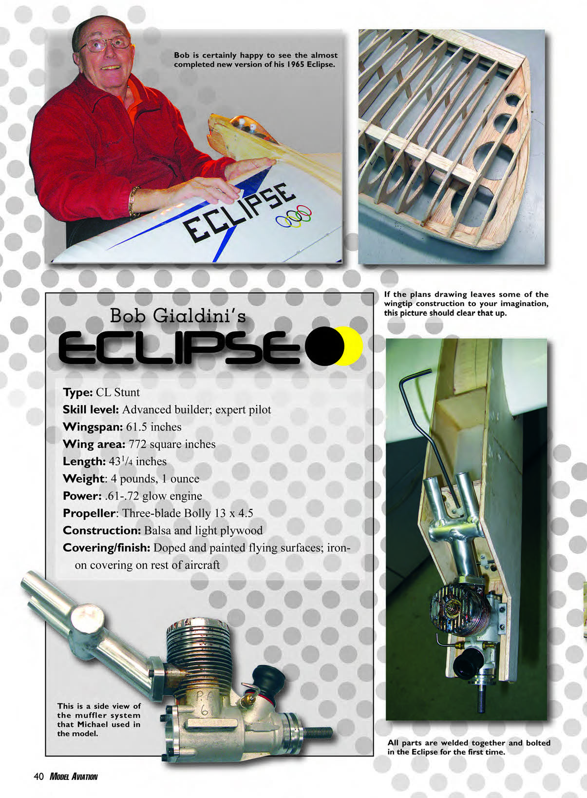
- Type: CL Stunt
- Skill level: Advanced builder; expert pilot
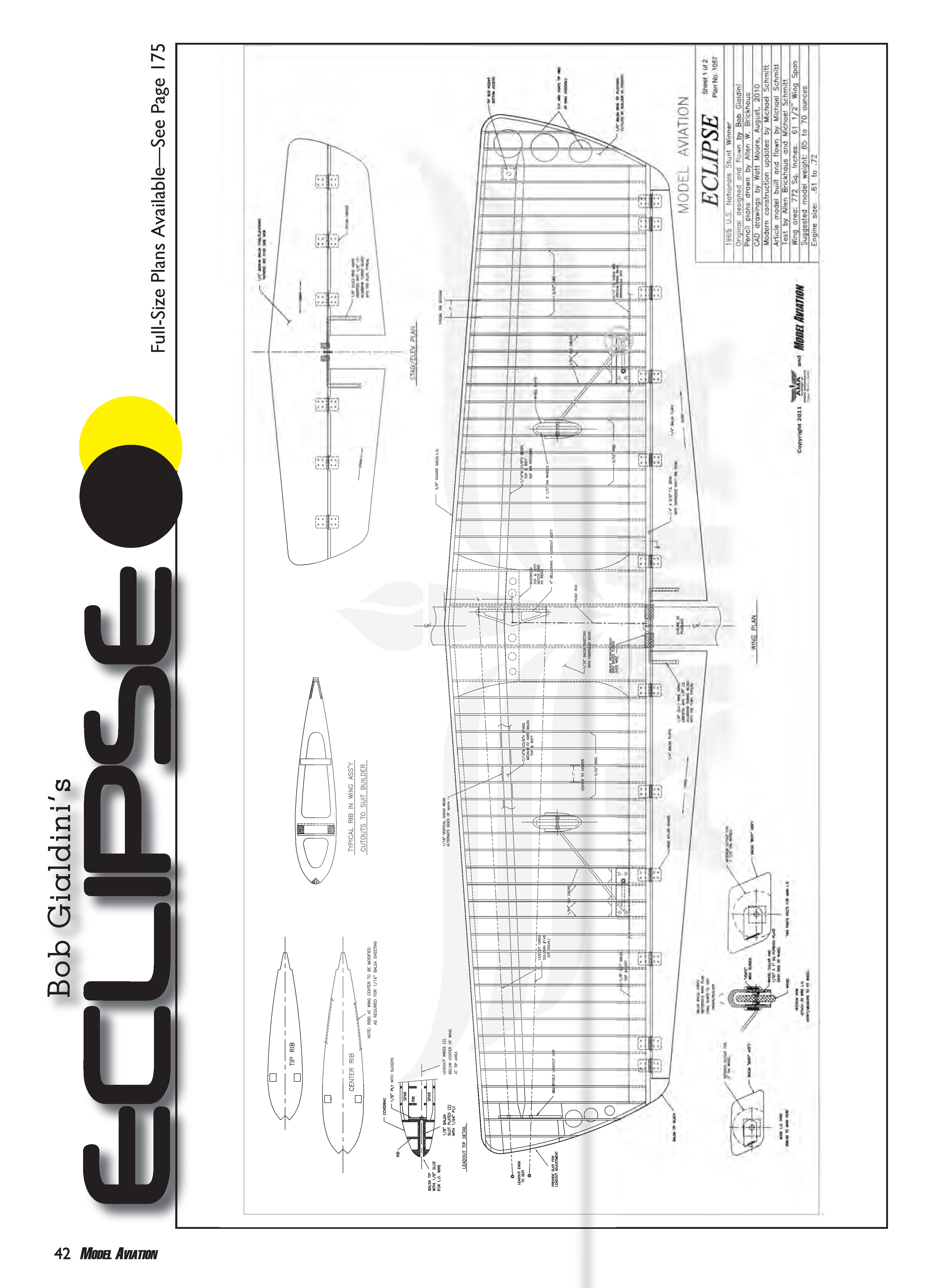
- Wingspan: 61.5 inches
- Wing area: 772 square inches
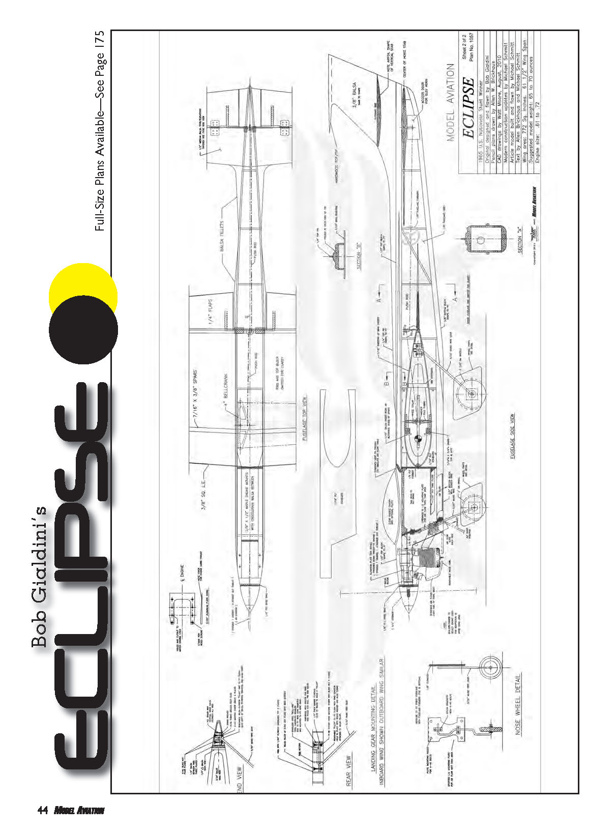
- Length: 43 1/4 inches
- Weight: 4 pounds, 1 ounce
- Power: .61–.72 glow engine
- Propeller: Three-blade Bolly 13 x 4.5
- Construction: Balsa and light plywood
- Covering/finish: Doped and painted flying surfaces; iron-on covering on rest of aircraft
CONSTRUCTION
The construction of the Eclipse is no different from that of the Sting Ray. The spar structure holds the ribs in place. Note the shape of the spar and the holes cut in the ribs to allow them to be slipped over the spar and located precisely in their respective areas for gluing. The basic structure of the box-type fuselage is simple, but the outward lines gave the impression of jets slicing through the stratosphere. Jets were symbolic of the fastest of the fast; the American F-86 Sabre jet inflicted much damage to the Russian MiG-15s, -17s, and -19s during the Korean Conflict. The Sabres were the speed demons of the time.
There were no plans for the Eclipse, but the original airplane was intact and in good shape. Bob did have the original rib templates he used and even a rib set. In January I received a pencil drawing of the Eclipse outside dimensions from Allen. I had also ordered a set of plans for the Sting Ray from the AMA Plans Service. Bob had said that he used all the construction techniques he used with the Sting Ray to make the Eclipse. So I started work using the drawing Allen provided.
I wanted the model to be Classic legal and to stay as true to the original design as possible; yet I wanted to update it with some goodies. I wanted to improve the aircraft by installing a Tom Morris control system with carbon-fiber pushrods, a 4-inch bellcrank, and adjustable leadouts. I also wanted to use a larger engine. Bob had said that the Lee Veco .45 he used had plenty of power. But this is a big airplane and I tend to build a tad heavy, so more power is good.
I also wanted removable flaps and elevators and access to the tank for maintenance and setting tank height. The vertical position of the tank can affect the type of engine run whether the model is upright or inverted. This presented a dilemma because the tank access, nose-gear mounting, and my PA .65 rear-exhaust engine want to live in the same space. I cover this more under the fuselage construction.
Wing construction
"Why all the ribs?" I asked Bob.
"I just loved the way the gliders looked with all of those ribs," he said.
"So it was just for style?" I asked.
"Yep," he replied.
I made a template using the most inboard rib and the most outboard rib. Then I counted the number of ribs needed—52—and doubled that. "Making two sets of ribs at the same time will make the stack of ribs taller," said Bob. "A taller stack of ribs will decrease the angle of the stack and keep the nose of the ribs closer to square." It's also handy to have an extra set of ribs around for additional work.
I found good balsa and cut the ribs roughly to the shape of the inboard rib. Then I drilled two holes through the stack of ribs and bolted the stack together using threaded rods, nuts, and washers. I shaped and tapered the stack of balsa ribs until they were uniform from one template to the other. This gave me the correct wing taper and rib positions.
A unique feature of the Eclipse is that the spars are sunk into the rib so you cannot see the spar when the wing is covered. I calculated the position of the spar on the stack of ribs and drew a location line on each rib. I made a square punch from square tube steel bought at The Home Depot, sharpened the edge, and punched the spar cutouts into each rib. I numbered each rib.
Next I lightened the ribs by cutting away the center, leaving a 3/8-inch circumference—being sure to leave extra meat around those areas that required it. I glued several vertical-grain 1/4-inch balsa stiffeners to each rib to restore some strength. I weighed each rib and put the heavier ribs on the outboard side. I also weighed the spars and put the heavier spars on the outboard side.
Bob Hunt recommends using a chunk of marble as a building board. Scraps of marble can be obtained for the asking at places that manufacture marble countertops. Look for a piece approximately 16 inches wide with one true edge. For alignment purposes I use the plans on top of the marble. At other stages I remove the plans and use the flat surfaces and edges of the marble for wing alignment.
I installed a 1/4-inch build shim under the most outboard rib to account for rib taper. Use the plans under your wing to help position the ribs. Slide each rib onto the spars. Start with the tip and use a square to help position the ribs vertically and then horizontally. Tack-glue the ribs using a drop of thin CA to hold them in position.
After you have positioned the ribs on either wing half, turn the wing leading edge up and rest it against the marble. This way you can check fore-and-aft alignment of the ribs. You want to see the surface of the trailing edge of the ribs contact the marble. Make adjustments to the spar cutouts in the ribs to get all the ribs touching the marble.
Lay down the wing and install the trailing-edge spars. If you have a rib that is out of place, do not force it down and glue it; that will cause a warp. Instead, with an X-Acto, adjust the spar cutouts in the rib to get a good fit. Shim any gaps with balsa as required.
The leading-edge spar is ready to be installed. Adjust the cutouts in the nose of the ribs by cutting away or shimming. Double-check your ribs for alignment, and hit all the wing joints with thin CA glue.
Before joining the main spars, ensure that the wing has no dihedral or anhedral. Position your 1/4-inch building shim under the outermost rib. Cut the spars according to the plans, and epoxy the spars together. Be sure to reinforce all of the spar joints.
I install the bellcrank in what would seem to be a backward position (so that the up-line is forward) on a post system. I use basswood top and bottom, inset into the ribs that span across the center section. The basswood is glued to the back of the main wing spars. During the lightening-the-ribs stage, I make sure to allow extra material in the ribs for the basswood inset and bellcrank clearance. Drill lightening holes through the basswood and ensure you leave plenty of meat around the bellcrank post. The center-section balsa sheeting will cover the basswood so it will be invisible once finished.
Install shear webs between the ribs, alternating frontside and backside of the spars. Install the wingtips, weight box, and adjustable leadouts.
Landing gear
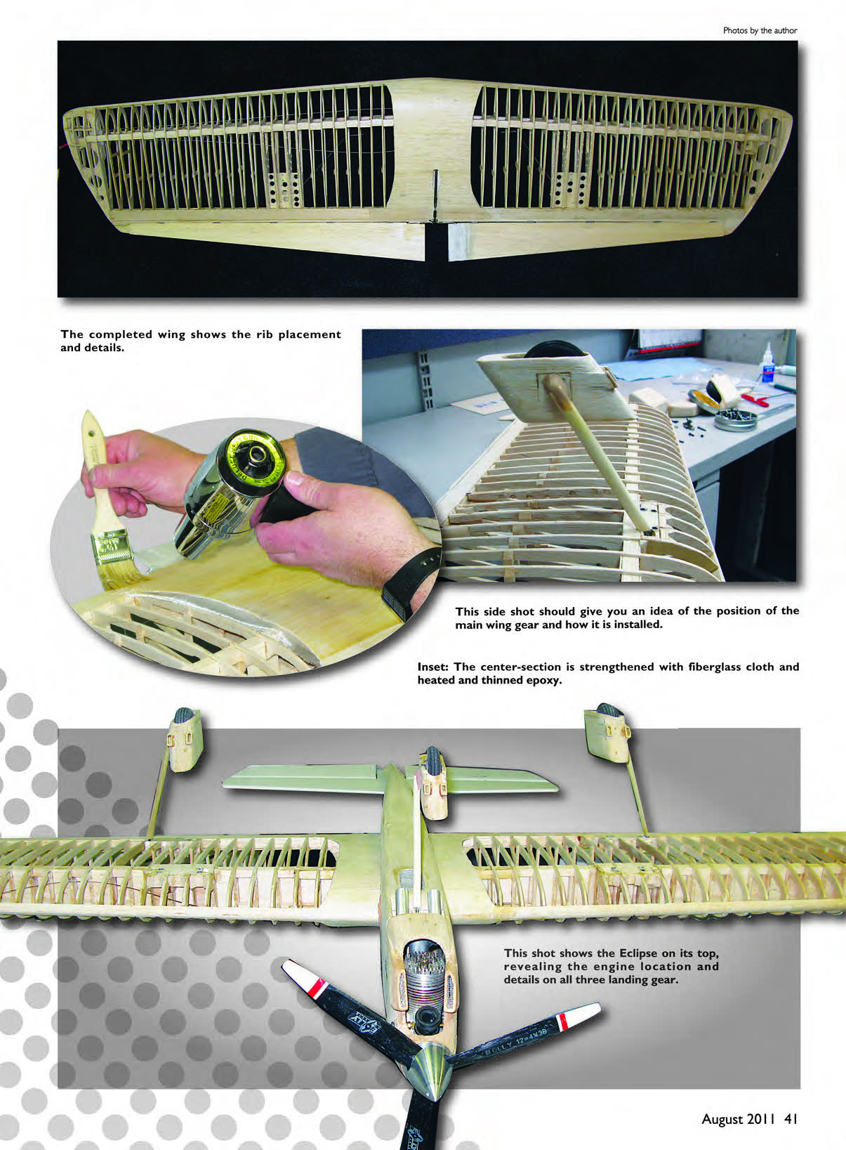
The Eclipse and Sting Ray are unique because the landing gear is mounted by the trailing-edge spar. The gear wire is bent forward and inward. For my first attempt I mounted the gear on a plywood plate, as shown on the Sting Ray plans. As the Eclipse took shape I reached the point of resting the airplane on its gear for the first time. I was disappointed to find that the larger propeller and flex in the gear did not allow enough propeller clearance with the ground. I had to uncover the wing and rethink the landing gear setup.
Jim Lynch showed me a method of mounting gear in his Super Ares: removable and therefore adjustable and changeable. Bob Hunt did a nice series of articles in Stunt News covering this method. Basically, the wing ribs by the gear are reinforced with 1/16-inch plywood to help absorb the shock of landing. The mount is a 3/4 x 3 1/4-inch block of spruce with a channel routed out lengthwise on the bottom. The block is inset into and across four ribs and also glued against the aft spar.
The landing gear wire mounts in the groove in the block and has a cover plate to hold the gear in place. A hardwood block is installed on the backside of the landing gear mount. A hole is drilled through the groove and into the hardwood block. The gear wire is bent so it will run along the channel and drop into the drilled hole. Because the landing gear is located at the trailing edge, there is not much depth for the block on the backside. As a result, reinforce the hole with a roll pin that has the same inside diameter as your gear wire.
Hinges and flight controls
I prefer removable flight controls that use a single hinge pin through all the hinges on each surface. After the wing and flight controls have been notched, slotted, and covered, it's time to install the hinges. Glue the hinges into the wing or horizontal stabilizer and let the glue dry. Mix 15-minute epoxy and fill the hinge slots with glue; wipe off the excess right away.
Insert the hinges into the slots and make sure that the hinge wire lays flat against the rear spar. Having the hinge pin resting flat against the spar assures that the hinges are located exactly where they need to be. This will give you a control surface that moves easily without binding. You can make a hinge-pin retainer from 1/16-inch-diameter tubing and insert it into the aft spar. Using the same method, epoxy the flight control surfaces onto the aircraft hinges that are already installed.
Fuselage
Bob Gialdini told me:
"Back in the day, we glued the fuel tanks in place. Before the Nats I had some trouble with leaks and had to access the tank by removing the canopy and cockpit floor.
"At the 1965 Nats the Eclipse developed another fuel leak. I mixed up a mixture of alcohol and epoxy and shot it into the tank and moved the airplane all around, trying to coat the inside of the tank with epoxy. Sealing the tank worked; I flew my flights and won the Nats.
"Afterwards bits of junk clogged the fuel system. I could not bear tearing into the cockpit again. So I stopped flying the Eclipse. About that same time I started to judge."
On my Eclipse, fuel tank access, rear engine exhaust, and nose landing-gear strut mounting coexist in the same fuselage compartment. The fuel tank compartment forward bulkhead is installed at a 15° angle so that the nose gear will tilt rearward per the plans. The nose-gear strut is mounted to the angled bulkhead with nylon straps found on RC airplanes.
To make this bulkhead removable, two top and bottom mounting supports were installed at the forward end of the fuel tank compartment. The 1/8-inch plywood fuel tank compartment bulkhead mounts to the two supports with four bolts and blind T-nuts. Access the tank by removing the four bolts and the bulkhead and nose-gear assembly. The tank slides out between the two supports.
Bob was the first to use a muffler in competition. If I had a PA .65 with side exhausts, my Eclipse would have been built the same way. However, I wanted to use an engine I had on hand (my PA .65 with rear exhaust) and make it fit.
Header muffler
After a typical fall Thursday evening of flying with my buddy Dennis Vander Kuur, we went to Portillo's for dinner. We talked about the Eclipse, and on a napkin we designed a header muffler that looks similar to a tuning fork. The dual exhaust ends at the tuning-fork exit beneath the fuselage on either side of the nose-gear strut.
To build the header muffler, I started with the header pipe used on PA engines. The boss end of the header is the base of the tuning fork. I cut the header pipe in half. The cutoff portion was turned sideways and trimmed to fit inside the width of the fuselage. The ends of the horizontal pipe needed to be welded shut.
I drilled three holes into the horizontal pipe to accommodate the exhaust flow. The center hole allows exhaust flow into the horizontal pipe, and the other two, at opposite ends and rotated 180° apart from the center hole, allow the flow to exit the dual 1/2-inch-diameter aluminum tubing exhaust stacks. Then I had the parts welded together.
I mounted the PA .65 on a .125-inch aluminum U-shaped plate and installed the plate on top of the maple engine mounts. I taper-sanded the plate to add a touch of downthrust and a tad of out-thrust, and then I drilled several lightening holes in the plate to keep it as light as possible. I used this plate method to help stiffen the nose and tie it all together.
The engine cowling had to be made differently to accommodate the larger PA .65, but I wanted the looks of the cowling to be as close to the original as possible. The original Eclipse inlet was covered with window screen so you could not see the engine at all. I liked the idea of a screen, but I needed to lay a finger on the venturi and pull the propeller through to prime the engine. So covering the entire inlet with screen was out. I also wanted easy glow-starter access.
I found blocks of balsa and carved the wood so it would fit over the engine. Next I cut away everything that did not look like Eclipse cowling. I even added working cheek vents, as were on the original. I covered those and the engine cooling exit with screen.
I used an 8-ounce Sullivan Products plastic clunk tank, set up in the uniflow configuration. I'm able to remove the nose-gear bulkhead and shim the tank up and down to produce even engine runs upright and inverted. When I assembled the engine mounts, I undercut the engine beams in the tank compartment to allow room to adjust the tank position.
Another unique feature of the Eclipse is two concave channels that run along the top of the fuselage. I asked Bob how he made those. He said he used several sizes of dowel rods covered with sandpaper. That method worked fine—just be sure to leave the top thick enough to sand into.
I had trouble finishing this area. I covered the fuselage with carbon-fiber veil and dope. As the dope dried, the carbon-fiber veil lifted over the channels, causing blisters. I sliced the blisters and used thin CA to glue them down. Windy Urtnowski suggested that if I had used thin CA to begin with, the carbon-fiber mat would not have lifted.
It was hard trying to get the ball link and carbon-fiber pushrod assembly to work in the small space that makes up the Eclipse tail. I found some small hardware and made it work. I also installed an access hatch so I can adjust the pushrod length and the control horn up-and-down adjustment.
When the airplane was covered but not painted, I drove up to Milwaukee to get Bob Gialdini's approval. He was very pleased with the Eclipse and said, "You did a yeoman's job." His only concern was that my wheel pants were too large. When Bob built the Eclipse, he was conscious of the aerodynamic and vertical CG of the airplane. He had put forth a real effort to make the landing gear and wheels as small as possible.
Flying
The Eclipse was ready for flight. After so much work, I was never so nervous. Because I fly from a grass field at Ned Brown Meadow (part of Busse Woods), where the Circle Cutters fly, and many contest venues I fly at have grass surfaces (including Classic at the Nats), the ability to land and take off from grass was important.
Once the Eclipse broke ground, I was in good shape. I added 1/4 ounce of weight to the tail and adjusted the elevator so that it turned to suit me. However, getting the model up and down proved to be a problem. Because of the larger engine and propeller, the aircraft needed to stand taller and the propeller needed to be kept mostly out of the grass.
The problem with the taller gear was that the main gear angles brought the main wheels farther forward and the nose gear wheel farther aft. The result was a small fore-and-aft landing gear footprint. The longer 1/8-inch-diameter wire gear was also flexing too much. My first flights had me cutting grass. If I pulled the handle to tighten the lines at the start of takeoff, the airplane would lean inward and my Bolly propeller would hit the dirt. It was far from graceful.
I tried many combinations of landing gear wire size, wheel sizes, and wheel pants and positions. The result was 5/32-inch-diameter gear wire; 2 1/2-inch Dave Brown Products thin, light wheels; and the nose gear wire bent forward instead of aft to regain stability. When I was satisfied with the landing gear configuration and performance, I needed to make another set of wheel pants.
Bob’s conversation with me about vertical CG and keeping the gear as small as possible kept coming back to me. With that in mind, I carved out the smallest possible wheel pants with the same shape as those on the original Eclipse.
The 2010 flying season is over, and I had a successful summer with the Eclipse. I thank Bob Gialdini for his help and great design and also all my friends who helped me through this project. If you would like an airplane that gets noticed wherever you go, this is it.
"The Eclipse is a very stable platform," Bob told me, and he was correct. I love the way it flies, and I think you will too.
MA Michael Schmitt [email protected]
Sources
- Wood, engines, building fixtures, paint stands, etc.:
Byron Barker of C.F. Slattery Home: (812) 944-8511 Cell: (812) 948-9167 [email protected]
- Controls, building fixtures, etc.:
Tom Morris (256) 820-1983 [email protected]
- Graphics, letterings, maskings:
Control Line Central (Jim Snelsen and family) (505) 332-8007 [email protected]
- All Stunt-type items, PA engines:
Aero Products (Randy Smith) (678) 407-9376 www.aeroproduct.net
- Spinners, Stunt supplies:
Brodak Manufacturing (724) 966-2726 www.brodak.com
- Graphics, maskings:
Louis Rankin (901) 837-1511
Transcribed from original scans by AI. Minor OCR errors may remain.

