
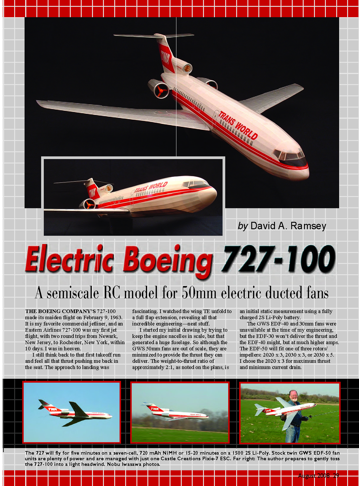
Electric Boeing 727-100
by David A. Ramsey
A semiccale RC model for 50mm electric ducted fans
THE BOEING COMPANY'S 727-100 made its maiden flight on February 9, 1963. It is my favorite commercial jetliner, and an Eastern Airlines 727-100 was my first jet flight, with two round trips from Newark, New Jersey, to Rochester, New York, within 10 days. I was in heaven.
I still think back to that first takeoff run and feel all that thrust pushing me back in the seat. The approach to landing was fascinating. I watched the wing trailing edge unfold to a full flap extension, revealing all that incredible engineering—neat stuff.
I started my initial drawing by trying to keep the engine nacelles in scale, but that generated a huge fuselage. So although the GWS 50mm fans are out of scale, they are minimized to provide the thrust they can deliver. The static weight-to-thrust ratio is approximately 2:1 (initial static measurement using a fully charged 2S Li-Poly battery).
The GWS EDF-40 and 30mm fans were unavailable at the time of my engineering, but the EDF-30 won't deliver the thrust and the EDF-40 might, but at much higher current draw. The EDF-50 will fit one of three rotors/impellers: 2020 x 3, 2030 x 3, or 2030 x 5. I chose the 2020 x 3 for maximum thrust and minimum current drain.
Keeping with a pair of EDF-50 CN12-RLC brushed motors, you can use a seven-cell, 720 mAh NiMH battery pack for roughly five minutes of flying time, or a two-cell (2S), 900–1500 mAh Li-Poly battery (8C recommended) for better voltage and longer flight—typically 15–20 minutes at mostly half-stick power. The motors' maximum static amp draw with the 2020 x 3 rotor is close to 6.8 A, and the tiny Castle Creations Pixie-7P ESC works perfectly with this motor/battery combination. Brushless motors would certainly give this Boeing 727 additional performance, but that is beyond the scope of this article. Do some testing to see if other power options will work for you.
Battery weight is an important consideration; 2.6–3.0 ounces is ideal. A seven-cell, 720 mAh NiMH battery with JST plug weighs about 3.2 ounces and may require adding tail weight to balance the model. My older (2004) two-cell, 1500 mAh, 8C Li-Poly with JST plug weighs 2.6 ounces and balances the model easily on the battery tray; however, that particular Kokam battery is no longer available. Because of weight increases caused by higher "C" ratings and the addition of balance connectors, a 1500 mAh Li-Poly can be slightly heavy; a two-cell, 900–1200 mAh Li-Poly will give excellent flight times while staying within weight limits.
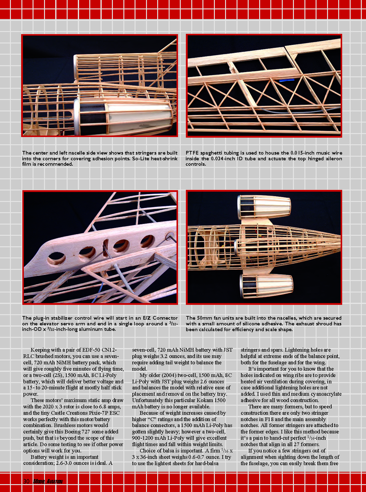
Choice of balsa is important. A firm 1/16 x 3 x 36-inch sheet weighs about 0.6–0.7 ounce. Use the lightest sheets possible for hard-balsa stringers and spars. Lightening holes are helpful at extreme ends of the balance point, both for the fuselage and for the wing. The holes indicated on the wing ribs are intended to provide heated-air ventilation during covering, in case additional lightening holes are not added. I used thin and medium cyanoacrylate adhesive for all wood construction.
There are many formers, but to speed construction there are only two stringer notches in F18 and the main assembly notches. All former stringers are attached to the former edges. I like this method because it avoids hand-cutting perfect 1/16-inch notches that must align in all 27 formers. If you notice a few stringers out of alignment when sighting down the length of the fuselage, you can easily break them free, realign them, and re-glue them before covering. With the stringers raised above the former they are easier to sand and you won't see the former after covering. Although there is less glue surface than with a notch, I can't see a loss in required strength.
The center and left nacelle side view shows that stringers are built into the corners for covering. The 50mm fan units are built into the nacelles, which are secured with a small amount of silicone adhesive. The exhaust shroud has been calculated for efficiency and scale shape.
All my former halves are constructed from two pieces of 1/16 balsa with the grain at 45°, as shown on the former templates. The seam line is at 90° to the former centerline, and a former template lines up with the edge and seam.
I like to make templates using 0.030-inch high-impact styrene plastic sheet. I spray the back of a copied plans former with 3M Spray Mount adhesive, let it dry, and press it on the sheet. Since styrene has no grain, it can be scored at the former lines rather than cut all the way through. After making all the cuts, gently flex the styrene at the scores and it breaks away; sand any rough edges smooth.
I cut out all balsa formers in pairs, using small (1/16 x 3/8-inch) pieces of double-stick masking tape to hold former blanks and templates in alignment. I cut parts with a No. 11 blade and sand them as necessary. Then I transfer all stringer centerline positions to the former edges and gently separate the formers with a thin palette-knife blade.
Two FS1 wing saddles and two delicate N3 nacelle formers need to be reinforced with 3/4-ounce fiberglass cloth. Lightly spray one side of the balsa sheet for these parts with 3M Spray Mount adhesive and let it dry for a few minutes. Carefully lay the fiberglass smoothly across the balsa and place a sheet of waxed paper or polyethylene film over the fiberglass to press it evenly to the sheet. Spread an even film of thin cyanoacrylate to bond the fiberglass to the sheet and follow with a light sanding.
I use an open-cell foam cradle to support the fuselage during construction and flight setup at the field.
CONSTRUCTION
Certain assembled parts will aid in other part assemblies; the following is the sequence I followed.
Wing Center-Section
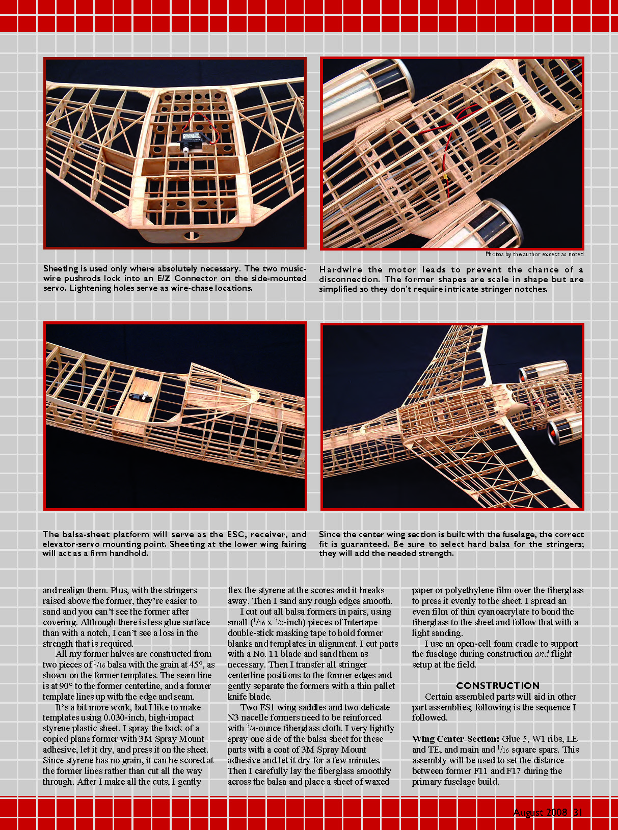
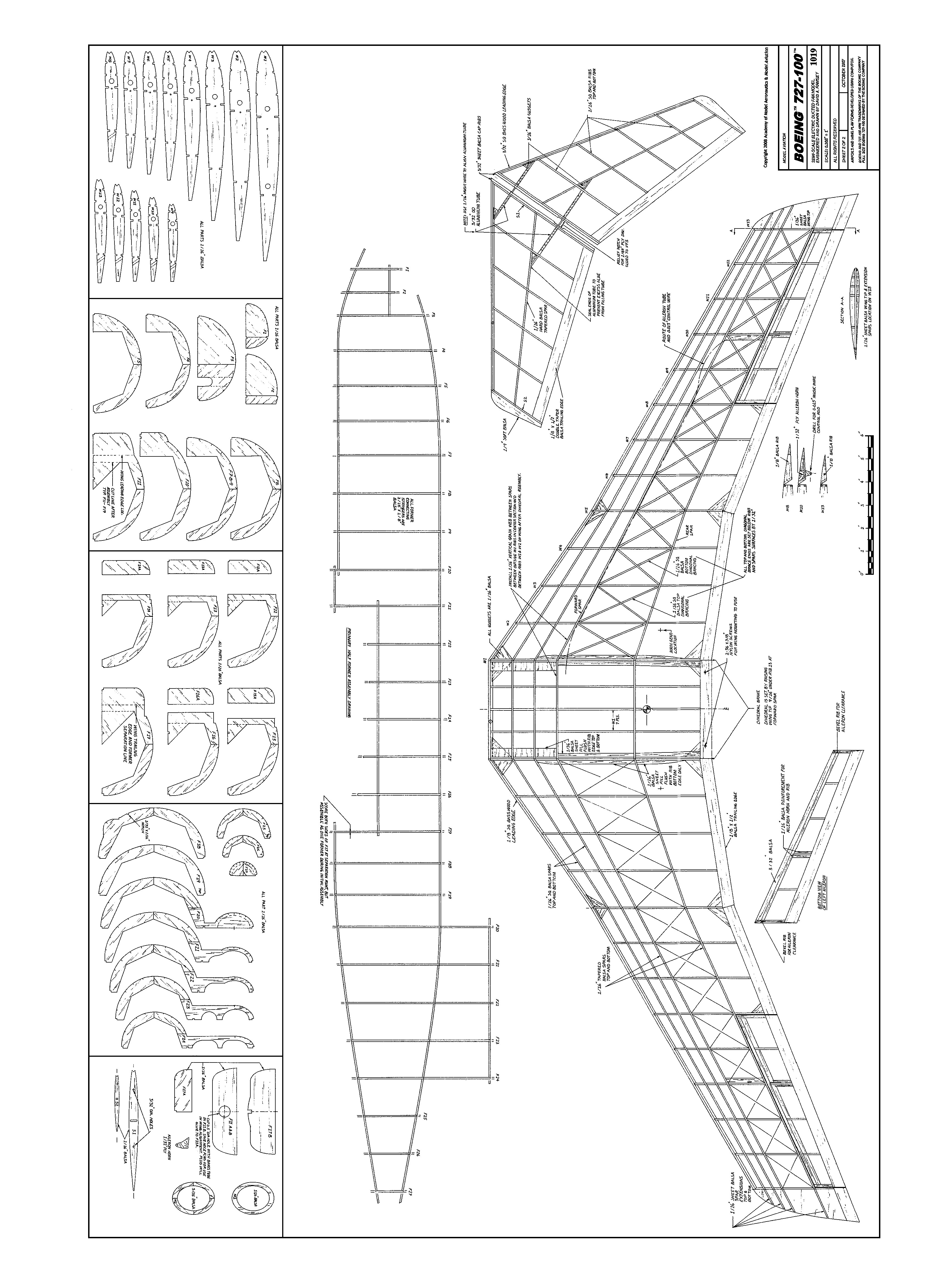
Glue five W1 ribs, LE and TE, and main and 1/16 square spars. This assembly will be used to set the distance between former F11 and F17 during the primary fuselage build.
Since the center wing section is built with the fuselage, the correct fit is guaranteed. Be sure to select hard balsa for the stringers; they will add the needed strength.
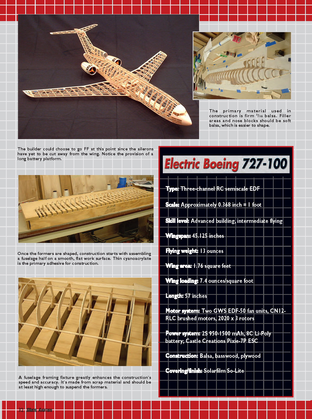
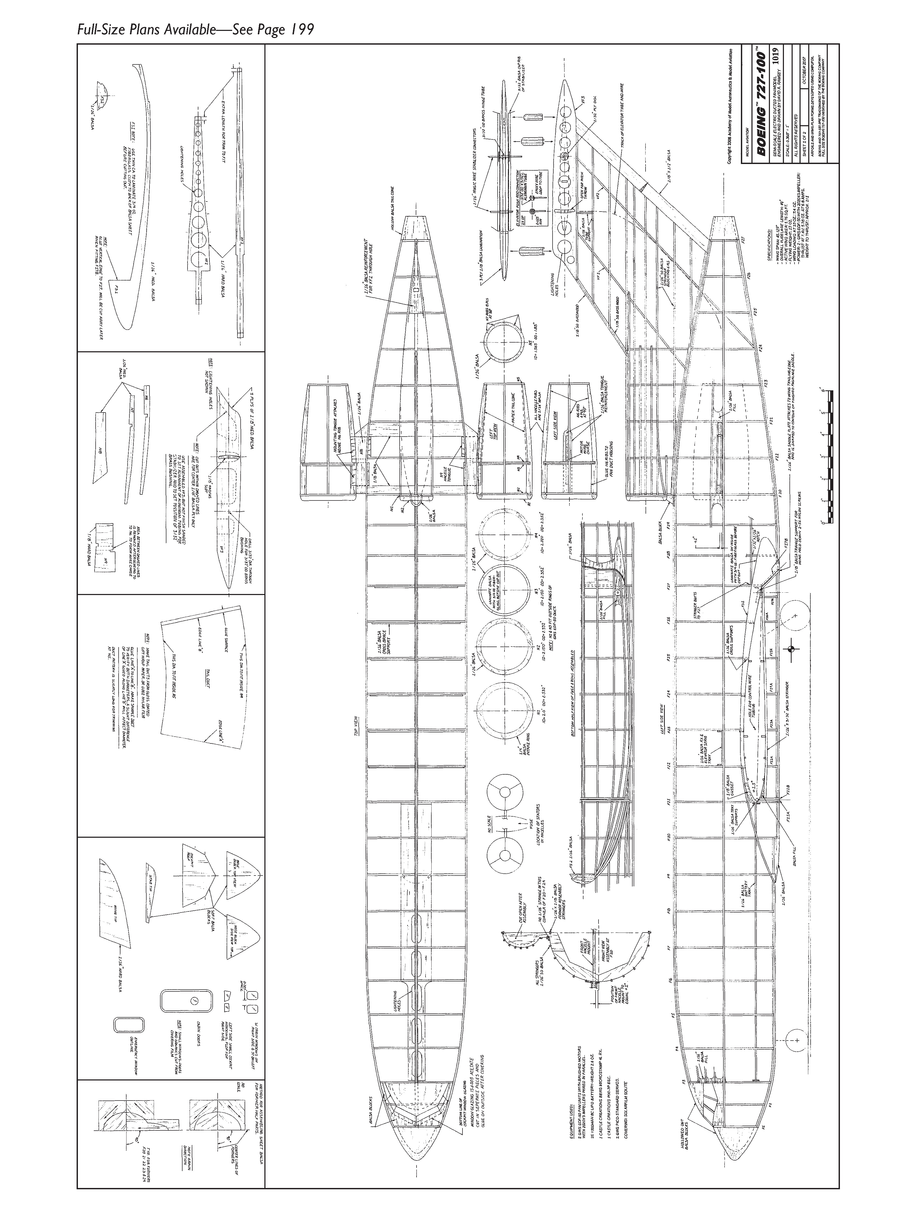
Specifications
- Type: Three-channel RC semiscale EDF
- Scale: Approximately 0.368 inch = 1 foot
- Skill level: Advanced building, intermediate flying
- Wingspan: 45.125 inches
- Flying weight: 13 ounces
- Wing area: 1.76 square feet
- Wing loading: 7.4 ounces/square foot
- Length: 57 inches
- Motor system: Two GWS EDF-50 fan units, CN12-RLC brushed motors, 2020 x 3 rotors
- Power system: 2S 900–1500 mAh Li-Poly (8C); Castle Creations Pixie-7P ESC
- Construction: Balsa, basswood, plywood
- Covering/finish: Solarfilm So-Lite
Building a long, straight fuselage made with half formers can be a challenge. I constructed a fixture from 3/4-inch medium-density fiberboard (MDF). The height of the sides and the notches cut in the surface give clearance for all formers. A removable front side allows the upside-down half fuselage to be guided in place while resting flat on the 1/16 x 1/8-inch center main assembly stringer.
The fixture is a bit more work for the short time it's used, but it's worth it for a straight fuselage with formers at 90°.
Initial Fuselage Assembly
Using the primary fuselage layout plan, pin down the 1/16 x 1/8-inch medium balsa stringers. Dampen all curved stringers with water to relieve bending stress, and let them dry a bit after pinning.
Keep all formers at 90°, and use small pieces of 1/16 balsa as spacers to maintain the height of the former center edge above the building surface. Use the wing center-section to set distance between F11 and F17.
With all formers in place at 90°, glue the top full-length 1/16-inch square center stringer from F5 through F22. Glue full-length stringers on each side of this center stringer from F5 through F22. The F11–F17 formers over the wing are held together by former webs that will be cut away after 1/16 balsa cross supports are added later.
Attach the wing saddle—FS1—but don't wrap the TE fairing portion around F17.
Carefully remove the fuselage frame from the building board, turn it over, and slide it onto the fixture with the 1/16 x 1/8-inch stringers resting on and taped to the fixture surface. Attach the remaining half formers, followed by the similar attachment of the 1/16-inch square stringers and wing saddle.
Remove the frame from the fixture, draw together pairs of previously attached stringers, and glue them to the formers. Water-dampen all bent stringers, especially for the nose, to relieve bending stress. Add all remaining straight-run stringers in opposing pairs.
Stringers at the fin base and center stringers along the bottom fuselage contributing to the front and back wing fairing will be completed later.
Flying Stabilizer
This assembly is next because the vertical fin top—VF3—is needed to conveniently assemble and align the swept symmetrical tapered stabilizer halves. When the stabilizer halves are assembled to the fin, the stabilizer top surface is flat. The stabilizer is built upside down on the plans with main ribs S1 and S2 set at 90° to the building surface.
The 3/32-inch balsa cap rib is made from sheet stock, drilled to match the tubing holes in the S1 rib, and finish-sanded to match the S1 profile. Accurately mark and drill 3/32-inch holes in S1, and assemble the S1 and S2 ribs to the tapered spar, LE, and TE.
Remove from the building surface and add 1/16-inch square stringer ribs in opposing pairs. Add the 3/32-inch balsa cap rib with its 3/32-inch drill holes aligned. The cap ribs need to be relieved at the axle pivot hole to clear the 1/32-inch plywood reinforcement disc that is attached to VF3.
Assemble the vertical fin top—VF3—from three plies of 1/8 medium balsa, noting the cutouts in the center plywood. Drill the stabilizer axle bushing hole at 90°, and cut the curved travel slot. Cut two 1/32 x 3/8-inch-diameter plywood axle bushing reinforcement discs, 3/32-inch center drilled, a length of 3/32-inch-OD x 3 1/2-inch-long aluminum tubing to fit the VF3 thickness, and 1/16-inch for the thickness of the two plywood reinforcement discs, but do not glue in place yet.
Do no further shaping now other than making sure the bottom surface is flat and square.
Pin down VF3 right-side up, with the sides at 90° to the building surface. Make lengths of 3/32-inch-OD aluminum tubing for each stabilizer half. One end of each tube butts to the LE or tapered spar, and the other ends are flush with the outside of the 3/32-inch cap rib. Plug the angle-cut ends of these tubes with a small piece of balsa or toothpick to prevent excess glue from running inside the tube.
Cut two lengths of 1/16-inch-OD music wire for stabilizer connectors. Make sure the stabilizer halves are right-side up—they will appear to have dihedral—and do a dry assembly to confirm the fit of all parts.
With everything square, tack-glue the tubes' angled ends to the tapered spar and LE. Tack-glue the tubing at the inside of the S1 ribs with a tiny drop of medium cyanoacrylate. Don't use thin cyanoacrylate; it could wick along the tube and glue the 3/32-inch cap rib to VF3.
Slide the stabilizer halves approximately 1/4 inch away from VF3, confirm that the 3/32-inch axle bushing is flush with the plywood reinforcement discs, and place a tiny drop of thin cyanoacrylate at the outside edge of both reinforcement discs and VF3. Keep glue away from the 1/16-inch wire axle and the brass bushing. Slide the stabilizer halves back and reconfirm alignment.
At this point the stabilizer halves can be removed. Add small gusset reinforcements to the aluminum tubing, and form a small fillet using medium cyanoacrylate around the tubing at the S1 rib. Finish gluing the plywood discs to VF3. Make sure the 3/32-inch brass tube has received enough cyanoacrylate to also be glued into VF3. VF3 is now free to be finished and assembled to the fin.
Wing Assembly
Measure and cut the tapered spars from 1/16 hard balsa. Make sure all spars, including the 1/16 square hard-balsa ones, are fitted and glued flush with the rib-surface edges. Each swept double-tapered wing panel is built right-side up and in one piece with the flat portion of the ribs resting on the building surface at 90°.
The front tapered spar is not a straight run from the root to the wingtip; it will run straight from W1 to W5 and then change direction to slightly forward as it runs straight to W13. Rib W5 is the point where the main tapered spars and the 1/16-inch square spars make a compound change in direction.
Rather than cut these spars to make angle changes, carefully crack them at the W5 rib until they are in alignment. Once thin cyanoacrylate is applied at the joint, the spar is much stronger than a butt joint.
The basswood LE and balsa TE are cut to follow the angle change. When cutting rib notches for the spars, it is initially easiest to cut them at 90°. But because all spars cross the ribs at an angle, open the notches following the angle as necessary to avoid a crush-to-fit assembly.
Align and pin the bottom front tapered spar to the plans, loosely pin the rear tapered spar to the plans, and pin the 1/16-inch square spar in place. Add the main and rear ribs and pin them in alignment. Add the W1 to W5 ribs, pin, add the bottom TE, and glue. Add the LE and glue it flush with the rib edges. Glue the top front tapered spar in place and add any additional stringers as needed.
When adding the top tapered spars and the top 1/16-inch square spars, don't glue them to the W1 rib until the wing panels are glued to the center-section and the dihedral is set.
Install gussets at W5, W8, and aileron-tube exit supports. Gussets at W1 are added after wing assembly to the center-section.
Add top diagonal 1/16-inch-square hard-balsa rib/spar braces. It's important that these diagonal braces not be forced into position, or the wing could end up warped. The top braces attach to the top front and top rear tapered spars at rib junctions and should be positioned 1/32 inch below the spar/rib top surface.
Remove wing panels from the building board to add the bottom 1/16-inch square spars and bottom diagonal braces. Since the wing can't be pinned flat when adding the bottom diagonal braces, make sure they are not forced to fit. After the diagonal braces are in place, add the wingtip and spar extensions.
Aileron separation is next, and the wing panel should be pinned down right-side up. The separation from the wing, while keeping the ribs attached to the TE, is a bit tedious. To make it easier, stabilize the TE ribs to be cut by gluing 1/16 x 1/8-inch balsa connector strips between the ribs; these are cut away later.
Once the aileron is cut away, make new aileron end ribs for W13 and W8 from 1/8 balsa. Stabilize these two additional ribs with balsa strip connectors to allow cutting and sanding the necessary angle in the ribs when adding the 3/32-inch balsa aileron LE. Once assembled, remove the balsa stabilizing strips by cutting them in the center with a diagonal wire cutter and then flexing/twisting the remainder off.
Sand the relief angle in the 1/8-inch balsa end ribs for up-aileron clearance, and add the aileron horn and rib reinforcement. Trim all spars, LEs, and TEs flush to the outside of the W1 ribs.
Start final wing assembly by pinning down the center-section right-side up. Line up the left and right panels against the center-section. The dihedral is 9/16 inch under W13 at the forward main tapered spar. Trim LEs, TEs, and top spars as dihedral is established and the W1 ribs come together. Pin the outer wing panels in place and use thin cyanoacrylate to glue the assembly.
Add the W1 1/16-inch balsa gussets, front tapered spar webbing between wing W1 and W2 and left and right outside center-section W1 ribs. Add balsa filler sheeting at the dihedral joint. Scrap 3/32 balsa works best for the filler between the 1/16-inch square spars because the excess can be sanded to follow the curve of the ribs.
Fit the Wing to the Fuselage
Add 1/16-inch balsa cross-supports to formers F11–F17. Cut away the former extension webs also held together by the 1/16 x 1/8-inch assembly stringer.
Add balsa triangular gussets at the corners of F11 and the wing saddle. Add the 1/8-inch hard-balsa wing-hold-down triangular gussets to wing saddle FS1 and former F17. I set this gusset in place so that there is a bit of free space between the wing and saddle to allow compression when the wing is screwed down.
Confirm and drill 1/16-inch pilot holes in the wing TE for 2-56 or 2 mm screws. Prepare former F11A so that the top edge has a 45° angle where it will meet the wing 45° LE. Align the wing center-section in the fuselage, check the fit to the saddle, and confirm overall alignment to the fuselage.
The wing incidence should naturally be set by the saddle. A bit less is okay, but not more than 1.5°.
With the wing level and square, the vertical centerline of the formers should be at right angles to the wing, and the left- and right-side center stringers should be at 90° and 270°. This alignment needs to be correct for placement of the fan nacelles and vertical fin to be accurate.
Holding this alignment, center front wing-hold-down F11A in position against F11 and the wing LE (the 45° in F11A butts against, but is not glued to, the 45° LE) and tack-glue it in place along the edges away from the wing. Former F11A also acts as a finishing edge to the 1/16-inch stringers ending at F11.
Drill the 1/16-inch pilot holes through the TE into the hold-down gussets. Remove the wing and open the TE holes for the screws. Harden the area around the hole with thin cyanoacrylate. Harden the gusset holes with thin cyanoacrylate and tap for threads; re-harden with cyanoacrylate and tap again.
If you feel that the 1/8-inch gusset thickness isn't enough for your threads, add another balsa thickness to the back of the gusset. If you think the TE feels weak at the screw head, add a small 1/64-inch plywood disc under the screw head glued to the TE.
Complete gluing F11A to F11. Reattach the wing to the fuselage. Sand an angle in F11B to match the wing, and attach F11B to the wing, centered against F11A. Slide a piece of polyethylene film between F11A and the wing to avoid gluing F11B to F11A.
Put a small drop of medium cyanoacrylate in the center of the hole plug you removed from F11B, and put the plug back in F11B so that it is glued to F11A. Sand the outside profile of F11B to match F11A. This completes the front wing hold down and alignment of the installed wing.
The fuselage wing saddle at the TE is next. Remove the bottom section of F17 at the wing TE line and from the bottom 1/16 x 1/8-inch stringer. Sand a 45° angle in the base of F17B. It attaches to F17 at the TE and lays back at a 45° angle. The notch needs to be fitted to the center stringer, and the edges need to be sanded to allow the free ends of the FS1 wing saddle to wrap around.
Trim the saddle at the F17B surface. Add filler balsa pieces between the saddle and the center stringer, and sand to shape. The 1/16-inch sheet-balsa wing portion of the saddle (there is no template) attaches to the wing TE, mates to the completed fuselage saddle, and is sanded to match the contour of the fuselage portion.
Add formers F12A–F17A to the bottom wing center-section, and finish all stringer attachments to complete the wing and fuselage fairing. Add any remaining fuselage stringers except for the fin. Add and finish-sand the fuselage tail cone.
Vertical Fin Attachment
Two things aid initial alignment. First, the fuselage with the wing attached needs to be level and secured to the building surface. Second, make two standing right-angle fixtures. To prevent the fuselage from moving too much, secure it to the building surface with long strips of blue painter's tape across the formers.
The right-angle fixtures are two base blocks of 3/4 x 3 x 4-inch MDF with two pieces of 3/4 x 1 x 12-inch MDF, one each, glued vertically to the surface of the blocks and aligning with the center of the 3-inch edge. These fixtures will work together against the top fin—VF3—to achieve a vertical, centered alignment.
Shape VF3's airfoil. Cut the 1/8-inch square basswood LE and hard-balsa TE to length and with matching angles. Glue the LE and TE to the base of VF3 so they're parallel with its sides. Set this fragile assembly in place on the fuselage. Use the fixtures, one on each side of VF3, to hold the fin vertical and in line with the fuselage centerline, and glue the LE and TE to the fuselage. Check this alignment frequently.
Fit the forward fin spar VF1 in place, followed by the rear VF2 spar. It will pass through a reinforced sheeted area, supporting a cutout in the center top 1/16 x 1/8-inch assembly stringer between F25 and F26. Confirm alignment again.
Add the left and right 1/16-inch square side center stringers in opposing pairs from center engine former F20 to the fin TE. Add the top two pairs, left and right, from the vertical center of F20 to the fin TE.
Add the stringers for the fin-and-fuselage junction. The line forming that intersection has no stringer at this corner. The stringer that runs along the base of the number-two engine and fin is raised from the corner by 1/16 inch, and the stringer that runs on the fuselage is offset by 1/16 inch so that the corners of those stringers run together. This provides definition and covering attachment.
Add the remaining center engine and vertical fin stringers in opposing pairs, and finish shaping the LE and TE of VF3. For the span between spars VF1 and VF2, add 1/16-inch square blocking pieces to prevent those stringers from flattening when covering is applied and shrunk.
Complete the fuselage by adding the nose, cockpit, and engine-two fairing blocks and intake ring, plus all filler pieces except the fan nacelles. Once cut to fit, the battery tray should have the surface prepared to accept fuzzy loop-and-hook self-adhesive tape.
The useful area of this tray for battery placement is from former F11 to F8. Seal the tray in this area with thin cyanoacrylate, and sand it smooth with 320-grit paper. Place two 5/16-inch-wide lengths of the hook tape on each side of the tray or to suit your mounting method. Don't overdo the Velcro; too much stress can be placed on the airframe during battery removal. With Velcro attached, glue the battery tray in position.
Fan-Nacelle Construction and Fuselage Attachment
There are no fan-nacelle former templates because it is more accurate to make them with a compass directly on the template material rather than copy from the plans. The balsa grain arrangement is the same as with the formers.
You could leave the EDF assembled or take it apart to keep the motor free of sanding dust. To disassemble, start by removing the rotor. In most cases, holding the fan housing in one hand and carefully grasping a three-blade rotor and pulling will do the job. These rotor blades are fragile. If one is flexed so much that the orange or black color turns whitish at the hub, it is no longer strong enough to use.
If the rotor won't pull off easily, drive a No. 2 sheet-metal screw into its center hole to provide a grasping point for removal.
Three things weaken the plastic rotor's grasp to the motor shaft: time (a tight fit will slowly relax), repeated removal and replacement, and excessive motor heat, which will expand the plastic.
Remove the motor's two mounting screws and withdraw it from the housing. The heat sinks are important for extended motor life; do not discard them.
The fan duct will become a structural part of the built-up nacelle; take care not to deform it. The plastic (nylon, I think) needs to be sanded where balsa is attached, which includes the face and edge of the front and back rings and the duct's outside surface. With the duct sanded, cyanoacrylate will work to hold it and the balsa in place.
Nacelle-ring formers N2 and N3 should be a snug, easy fit to the duct rings and fit flush to the outside surfaces. N4 is aligned and glued to N3. Add N6 nacelle ribs at 90° to the duct while noting the position of the duct stators in relation to the mounting of a left and right nacelle to the fuselage (see the small drawing on the plans for reference).
Position and glue N5 to the N6 rib ends at 90° and check for centering. Add the N7 ribs. Lightly tack-glue the N1 intake ring in place and sand to shape with the inside of this ring blending with the inside surface of the duct.
Once the intake rings are shaped, remove them for sealing and finishing with a few coats of silver enamel, as is done with the smaller oval number-two engine intake ring. I glue the painted intake rings in place, after covering, with a bit of silicone adhesive because silicone won't attack the enamel paint.
Make the N9 1/8-inch hard-balsa nacelle mounting tongues, nacelle fuselage supports, and four N8 1/16-inch balsa fuselage/nacelle support covers. To aid alignment of the fuselage nacelle supports, set the front and rear supports centered on top of the left and right center fuselage 1/16-inch square stringers and against formers F20 and F22.
Measure the distance between, which should match the width of the nacelle mounting tongue, and cut 1/8 x 1/4-inch balsa spacers. Tack-glue these to the ends of the supports, creating a one-piece square, flat frame.
For a 1° support setting in the fuselage, the rear support should be 1/16 inch above the 1/16-inch square stringer, and the front support should be up just a tad under 1/8 inch, with less being better than more.
Add 1/16-inch balsa fill between stringers, per the plans, to box in the nacelle mounts. Remove the temporary support spacers, add the N8 1/16-inch balsa covers, and sand to shape.
Check the fit of the nacelle mounting tongues. They should go easily into the mounting slot. It helps to score the wire chase cut in the mounting tongues, but keep them in one piece and attach above the appropriate N6 rib of the nacelle.
Tack-glue at the outside edges of the tongue, remove the wire-chase portion, and complete the gluing along with the balsa reinforcements. The wire chase must accept the passage of the motor wire and JST plug. Sand the outside edges of the mounting slot to match the nacelle.
Make the paper tail cones. Glossy-on-one-side black gift-wrap paper works best. Thin acetate or 0.002 drafting Mylar will work, but paper makes it easier to align the cone overlap and adhere with Elmer's white glue.
The exact sizing of this cone can be tricky. When making the lineup at the overlap for gluing, a slight change in either direction can make quite a change in the final diameter. Make a cone template and a couple copies from copy paper to make a few samples.
The cone's large end needs to fit inside the N4 inside diameter (ID), and the smaller diameter needs to fit the N5 ID. The cone will be slightly longer for trimming flush with the outside of N5. Once you have noted the correct placement of the overlap, make the cones from the chosen material. Insert the finished cone through the N5 ID by carefully forming it into a "U" shape without creasing. Use cyanoacrylate to adhere the front and rear of the cone to their formers.
Before reinstalling the motor, extend the motor wires: cut the motor wires 3/4 inch back from the JST plug and add 4.5–5 inches of red and black wire of the same gauge. Cut a small hole in the paper duct at the wire-chase slot in the mounting tongue.
You will need a tool to fit over the back of the motor to install and add resistance when pushing on the rotor, because the completed balsa nacelle needs to be handled carefully. The tool is made from a 10-inch length of 3/4-inch-diameter dowel, 1/2-inch center-drilled on one end to a depth of 3/4 inch. The drilled end of this dowel fits over the back end of the motor and presses against the heat sink. Cut a notch in the drilled end to clear the motor wires. The opposite end of the dowel is covered with a thin, dense foam disc or the loop side of a piece of Velcro to soften the pressure of pushing against the motor's capacitor.
I used a length of wire insulation forced over the motor shaft to guide the motor through the duct. The heat sink should be at the back edge of the motor when the foam-covered end of the dowel is used to push the motor in place. The dowel's notched end is then used to seat the heat sink against the stator.
Before inserting the motor, check the relationship of the plastic mounting tabs to the motor screw holes; choose the motor position that allows the motor wires to easily pass through the wire-exit chase. Also make sure the heat sink is a snug fit on the motor case. Use a tiny bit of blue thread locker on the motor screws, but do not overtighten or the plastic mounting tabs will collapse and break.
Use the notched end of the motor mounting tool to offer resistance as you press the rotor straight—no cocking—fully onto the motor shaft. The rotor can then be replaced two or three times and be tight enough to stay on.
Aileron and Flying-Stabilizer Control Setup
I like to use plastic tubing to house the control wires. Du-Bro micro tubing will work, but I prefer PTFE spaghetti tubing. PTFE offers very low friction for music wire running inside.
Cyanoacrylate will stick the tubing to balsa if the tubing is sanded to make the outside surface fuzzy; the tubing will stay put if it's tacked down in enough places. GOOP adhesive works a bit better but is messy.
Make sure the cut ends of music wire are smooth before running through the tubing. Before tacking the tubing in place, the control music wire should be inside; the tubing will hold its shape and position better.
(PTFE tubing makes great cyanoacrylate applicators. Trim off a new bottle tip just enough to allow tight passage of the tube; the tube is reusable and easy to remove for recapping the bottle. The 0.022-inch ID works nicely with thin cyanoacrylate.)
The aileron wire is two lengths of 0.015-inch music wire, and it runs in a 0.034-inch-ID PTFE tube. Wire attachment to the aileron horn is a 90° "L" bend, with a small-ID piece of PVC wire insulation as a keeper glued to the wire with a dab of GOOP adhesive. Each opposite end of this wire will cross and go through a Du-Bro Mini E/Z Connector (item 845) in the wing center-section for attachment to the aileron servo horn.
With the aileron servo mounted on its side, you can just get a long, thin screwdriver blade through the spars to tighten the E/Z Connector screw. With thread locker this screw will hold both 0.015 wires, but once the ailerons' final positions are set, I add a drop of epoxy on each wire at the outside of this connector.
The flying-stabilizer PTFE 0.038-inch-ID control tubing and 0.025-inch music wire need to be supported on every other former with a cross strip of 1/16 balsa as it makes its way through the fuselage to the vertical-fin rear spar and up to the forward-stabilizer 1/16-inch connecting wire. The control wire will start in an E/Z Connector on the elevator control horn and end in a single loop around a 3/32-inch-OD x 3 1/2-inch-long aluminum tube.
The stabilizer forward 1/16-inch music-wire connecting rod will pass through the control-wire aluminum tube to move the stabilizer on the rear hinge connecting wire. The 0.025-inch music-wire loop should be a tight fit on the aluminum tube; add a bit of epoxy as insurance.
Equipment setup: Before covering, set up the receiver on the elevator servo tray, connect the receiver to the ESC, and confirm ESC wiring to the fan motors and battery. Servo and receiver-tray placement is also a CG consideration.
For the ESC motor wires, I attached two red and black wire pigtails with female JST plugs and soldered them for a parallel connection. The ESC is attached to a small 1/16-inch balsa strip glued between formers.
As a rule, keep motor and battery wires as short as possible without making the connections difficult. The receiver antenna passes through the fuselage interior and exits through the tail cone.
For aileron control movement, I set my endpoints for as much down aileron as is available and an equal amount of up, or a bit more. For the elevator, I use full available up and down throw.
Finishing and Covering
Besides general finish sanding (320-grit), spend time rounding and shaping all the basswood LEs except for the LE portion of the wing center-section; its flat 45° is necessary for the hold-down to work.
All balsa, especially stringers, that has cyanoacrylate hardened on the surface needs to be sanded smooth. Any rough surface areas will show up during covering.
A plastic kit model is helpful in locating aircraft surface detail. I used a Hasegawa 1/200-scale Boeing 727-200 as the primary source for scaling and detailing. There are many liveries of the Boeing 727-100 and numerous websites on which to view them. I picked Trans World because I, ah, love to cut out windows. My second version will be FedEx or maybe DHL.
I chose Solarfilm So-Lite for covering and graphics. To learn about this material, search for SoLite on RCGroups.com; you'll find excellent information.
I used a GWS iron with the small flat shoe, set to low, for initial covering attachment. For shrinking I used a standard covering iron. It works best to complete a part's covering job to be as wrinkle-free as possible before attempting shrinking. Do the shrinking "in the round," slowly, to avoid airframe warping. I don't recommend using a heat gun because shrinking is too hard to control. Do not underestimate So-Lite's shrinking power!
The fuselage is covered mostly in strips—three stringers or two open areas between stringers at a time. Check the finished wing and stabilizers for warping after shrinking the covering. A small amount of equal wing washout is okay.
The ailerons are hinged with 1/2-inch-wide x 3/4-inch-long pieces of So-Lite between rib bays. Starting from the top, set the aileron in place in the full-down position and iron on the five pieces, keeping the end pieces close to the aileron ends. Flip the aileron up until it rests on the wing surface, and iron on five more pieces in the same positions. You may need to reheat the top hinge strips until the aileron holds a neutral position and is relatively easy to flex.
The cockpit window glazing is thin acetate, with each of the six window panes cut separately and glued with canopy adhesive after covering.
Final Assembly
Battery weight and location will determine the correct CG. Placement closest to F11 will simplify installation and removal.
To aid battery removal, add a 3/8-inch-wide strip of fiberglass filament tape wrapped around the battery so you have a long overlapped strip on one end. You can view the battery placement by looking through the cockpit windows and the viewing window in former F3.
To assemble the stabilizer halves to the fin, mark the center point of each 1/16-inch connecting wire. Apply a bit of clear silicone sealant to one end of each wire, and install them in one stabilizer half. The halfway point marked on the 1/16-inch wire should match the fin centerline. Wipe off the excess and let cure. Once the silicone has cured, install that stabilizer half, capturing the elevator control-wire tube, and slide into position.
Apply a minute bit of oil to the brass bushing and to the aluminum push-wire tube. Put a bit of silicone on the 1/16-inch wire ends, and slide the remaining stabilizer half in place while keeping track of and removing excess silicone. Keep a minuscule amount of side-to-side play. Check for free movement after this silicone has cured. It takes only a small amount of silicone to hold the wires in the tubing and still allow stabilizer removal later, if necessary.
Silicone also holds the fan nacelles in place. Install the nacelle, allowing a 1/8-inch space to remain. Apply a small amount of silicone at each end corner of the nacelle tongue and slide the nacelle home. Wipe off any excess. This is enough to hold the nacelle in place and still allow removal. If you're worried, you could insert a couple of short pins, but they alone should not be used if the tongue is the least bit wobbly in the mount.
Flight Characteristics and Tips
The plans' CG location is optimal for smooth, stable, controllable flight. Moving the CG aft will cause the aircraft to become unstable in pitch and uncomfortable to fly.
Depending on ready-to-fly weight, cruise speed will be close to half transmitter-throttle-stick position using a two-cell Li-Poly battery. Prevailing winds should be less than 5 mph.
At 13 ounces flying weight, the 727 is not fast or highly powered, and the controls will not act quickly to counter higher winds or gusty conditions. The model will loop with a full-power diving entry and roll with a full-power, slightly climbing entry; it will not maintain inverted flight. The power-off glide is lovely.
With calm wind conditions and after rehearsing your checklist, the model is easy to hand-launch. Hold the rear wing fairing between thumb and index finger on each side, with the middle finger lightly supporting the wing center-section. Bring the power up to half stick and give the 727 a gentle, firm, level toss. It may lose a bit of altitude on launch but will recover quickly. Continue adding power as necessary for climb-out. During the first flight, gentle aileron turns will require almost no elevator input to keep the nose up.
Be prepared for a long glide on the first landing. Once in ground effect, keep adding up-elevator to hold a slightly nose-up attitude until it settles for touchdown.
My prototype showed no tendency to tip stall with high bank and high elevator-input turns using cruise power. In fact, when trying to induce a stall from about 100 feet, I kept adding aileron, up-elevator, and power until I had nothing left—it just stayed there and wouldn't stall. A straight-ahead power-off attempt to stall will see the nose drop as airspeed runs out, followed by an immediate recovery with neutral elevator. Nothing like a light wing loading!
If you have questions, put "Boeing 727-100" in the subject line.
MA David A. Ramsey [email protected]
Sources
- McMaster-Carr (polystyrene sheet plastic, PTFE spaghetti tubing, double-stick masking tape)
(630) 600-3600 — www.mcmaster.com
- GWS (electric power system)
(909) 594-4979 — www.gwsus.com
- Castle Creations (ESC, receiver)
(913) 390-6939 — www.castlecreations.com
- Du-Bro (hardware)
(800) 848-9411 — www.dubro.com
- Top Flite (trim-seal tool)
(800) 637-7660 — www.monokote.com
- Solarfilm (So-Lite)
(615) 373-1444 — www.solarfilm.co.uk/
Transcribed from original scans by AI. Minor OCR errors may remain.

