

Electric Flash
by Harry Stewart
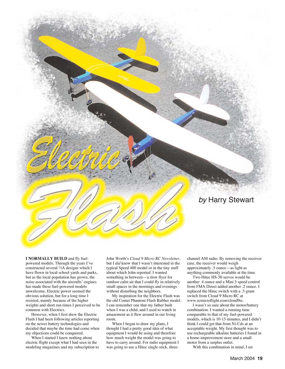
I normally build and fly fuel-powered models. Through the years I’ve constructed several 1/2A designs which I have flown in local school yards and parks, but as the local population has grown, the noise associated with the aircrafts’ engines has made these fuel-powered models unwelcome. Electric power seemed the obvious solution, but for a long time I resisted, mainly because of the higher weights and short run times I perceived to be common with electrics. However, when I first drew the Electric Flash I had been following articles reporting on the newer battery technologies and decided that maybe the time had come when my objections could be conquered.
When I started I knew nothing about electric flight except what I had seen in the modeling magazines and my subscription to John Worth’s Cloud 9 Micro RC Newsletter, but I did know that I wasn’t interested in the typical Speed 400 model or in the tiny stuff about which John reported. I wanted something in between — a slow flyer for outdoor calm air that I could fly in relatively small spaces in the mornings and evenings without disturbing the neighbors.
My inspiration for the Electric Flash was the old Comet Phantom Flash rubber model. I can remember one that my father built when I was a child, and I used to watch in amazement as it flew around in our living room.
When I began to draw my plans, I thought I had a pretty good idea of what equipment I would be using and therefore how much weight the model was going to have to carry. For radio equipment I was going to use a Hitec single-stick, three-channel AM radio. By removing the receiver case, the receiver would weigh approximately 0.5 ounce — as light as anything commonly available at the time. Two Hitec HS-50 servos would be another 0.4 ounce and a Mini 5 speed control from FMA Direct added another 0.2 ounce. I replaced the Hitec switch with a 0.5-gram switch from Cloud 9 Micro RC at www.rcmicroflight.com/cloud9rc.
I wasn’t so sure about the motor/battery combination. I wanted a running time comparable to that of my fuel-powered models, which is 10–15 minutes, and I didn’t think I could get that from Ni-Cd cells at an acceptable weight. My first thought was to use rechargeable alkaline batteries I found in a home-improvement store and a small motor from a surplus outlet. With this combination in mind, I set about designing the airframe. The completed Electric Flash was quite attractive, but the available power was barely enough to keep it in the air.
When my original motor/battery combination didn’t work out, I looked into lithium-metal batteries. However, since I was wanting to keep this a low-cost project and I would not only have to buy the batteries but the special charger and Electronic Speed Control (ESC) that they require, I decided against them. At that point I realized that I really didn’t know what I was doing, so I began researching the web sites of every electric-related supplier I could find. I finally found what I thought would be an acceptable combination when I downloaded Dick Miller’s “Motor Characterizations” charts from the Internet. According to the charts, a VL HY-50D motor on six cells would give me the power I needed. Six of the then-new AAA NiMH cells would give me the duration I was after at an overall weight of approximately 8 ounces for the model, and I could charge them with my existing Ni-Cd chargers. I bought the motor and a couple of propellers from Cloud 9 and had two 550 mAh AAA NiMH battery packs made at the nearest Batteries Plus store. Then I had an attractive model that flew! I was more than satisfied. It would do 15 minutes in a school yard, never going higher than 50 feet. At a slightly larger site with some lift, 20–25 minutes was the norm.
Unfortunately, somewhere I missed the part about never using more than 6 volts with the HY-50D! Since I rarely used full power after initial takeoff, it took me 10–12 hours to burn the brushes up in the motor, but eventually I did. Even so, I would have gladly accepted that lifespan and replaced the motor, but the HY-50D was out of production and no longer available. (It is available again from Cloud 9.)
- Electric Flash
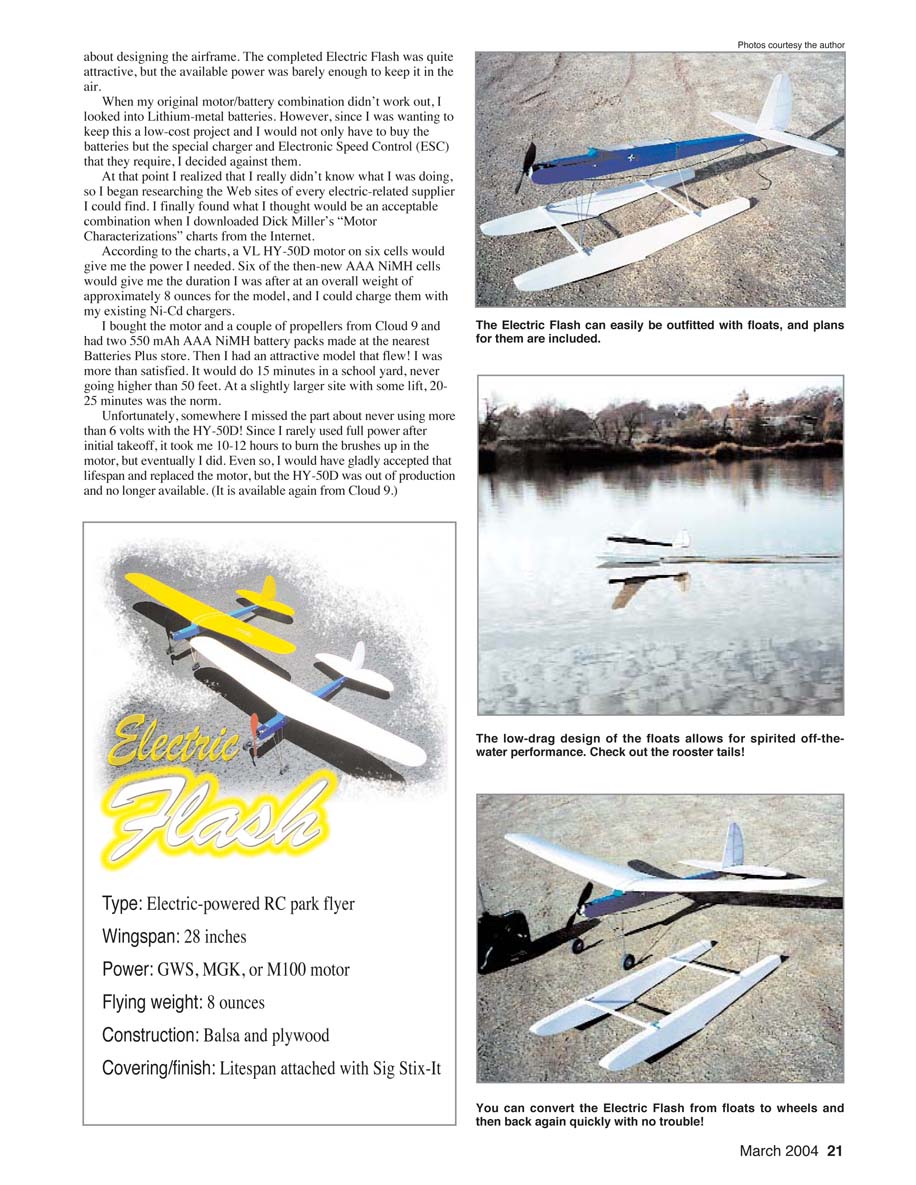
- Type: Electric-powered RC park flyer
- Wingspan: 28 inches
- Power: GWS, MGK, or M100 motor
- Flying weight: 8 ounces
- Construction: Balsa and plywood
- Covering/finish: Litespan attached with Sig Stix-It
That's the bad news; the good news is that now there are several small electric motor/gearbox units in the 1-ounce category that are suitable for the Electric Flash. More good news is that the AAA NiMH cells have been upgraded to 700 mAh capacity and are now readily available and cost less than my originals. And the best news of all is that with the new Lithium-Polymer batteries, flight times are up even more and the weight is down compared to the NiMHs.
I am pleased with the Electric Flash. After a couple of false starts I got exactly what I was looking for: a gentle, relaxing, slow-flying park flyer that is able to handle a good breeze with excellent flight duration, and the bonus is that it has also turned out to be a good soarer and floatplane.
The first prototypes have been flying for more than three years, and I have built several since then. So far they have flown with a number of small motors—some more successfully than others.
I flew the first prototype for a long time with a GWS A motor (aka the Lite Stick motor) from Balsa Products, at www.balsapr.com, and an APC 8 x 6 slow flyer propeller from Landing Products. This combination will weigh roughly 8 ounces total flying weight. A GWS C with the same propeller works well too.
Then I upgraded to what I refer to as the "big block" motor: an EMPS MGK motor/gear/propeller combination from Penn Valley Hobby Center. This unit raises the total figure to approximately 8.75 ounces flying weight, but the model will have much more power. And more recently I have used the M100 motor/gearbox from Jet Set Models.
For relaxing slow/park flying, the GWS is the way to go. If you just have to have more performance, the MGK or M100 will provide it. Because the MGK will fly the Flash at low power settings, the flight times can be almost the same as with the GWS.
EMPS cautions against prolonged use at full power with the MGK on six cells. Believe me, you won't need more than a few seconds of full power at any time with the MGK. The M100 uses slightly less current and has no such restriction.
The GWS units come with a capacitor across the motor terminals, but I had to add two more from the terminals to the case to eliminate glitches with my Hitec AM Focus 3. I used RadioShack 0.1 µF part 272-109AS. On the MGK I used three 0.1 µF capacitors supplied by EMPS. I used three on the M100 as well.
Since the Electric Flash was first designed, there has been an enormous proliferation of micro radio control (RC) equipment suitable for it: microreceivers, several 6- and 9-gram servos, more choices of electronic speed controls (ESCs), lightweight iron-on coverings, micro hardware and wheels from Du-Bro at www.dubro.com, and, best of all, the newer lithium-ion and lithium-polymer batteries. (You need a special charger for lithium batteries, but there are many more choices and they are more reasonably priced.)
Currently my favorite power combinations are the MGK with a 1200 mAh lithium-polymer and the M100 with a 700–1000 mAh lithium-polymer, although the 700 mAh NiMHs still work well with either.
CONSTRUCTION
If you have scratch-built, or plans-built, a couple of models, you can probably build the Flash from the plans. In case you don't have that experience, I will try to explain how I built mine.
Wing
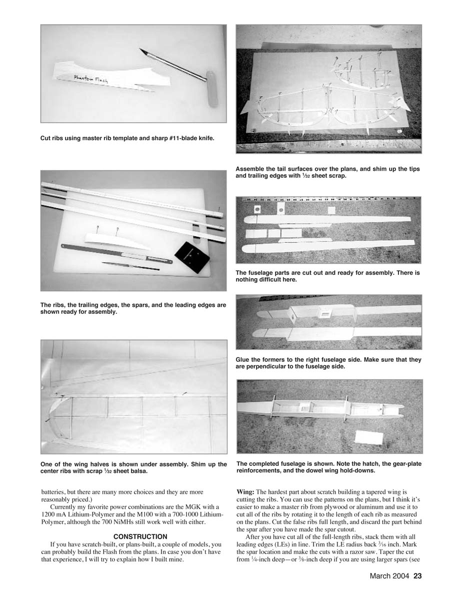
The hardest part about scratch building a tapered wing is cutting the ribs. You can use the patterns on the plans, but I think it's easier to make a master rib from plywood or aluminum and use it to cut all of the ribs by rotating it to the length of each rib as measured on the plans. Cut the false ribs full length, and discard the part behind the spar after you have made the spar cutout.
After you have cut all of the full-length ribs, stack them with all leading edges (LEs) in line. Trim the LE radius back 3/16 inch. Mark the spar location and make the cuts with a razor saw. Taper the cut from 1/4-inch deep—or 3/16-inch deep if you are using larger spars (see the following)—at R-1 to 1/8-inch deep at R-8.
Use a Master Airscrew Balsa Stripper from Windsor Propeller Co., Inc. to trim the 1/32-inch center sheeting. If you can find straight pieces of 1/4 square and 3/32 x 1/4 x 48-inch pieces for the LE and the spar, you will only need one of each; otherwise, you will need two pieces of 3/16-inch, 1/4 square, and 3/32 x 1/4-inch stock. (If you are going to use the MGK motor, you might want to increase the spars to 3/32 inch or even 1/8 x 3/8 inch.) The trailing edge (TE) is 1/8 x 1/2-inch TE stock.
Cut the LE, TE, and spar to the approximate length; leave a little extra. Mark the rib locations on the LE and TE from the plans and cut the 1/16-inch-deep slots for the ribs. Only slot the TE for R-2, R-4, R-6, and R-8. I used a hacksaw blade with a couple of scraps of balsa glued to it with cyanoacrylate as a depth gauge. I finished the slots with a jeweler's file. Pin the two spars together at one end, and taper the spar from 1/4 inch to 1/8 inch with progressive passes with a Master Airscrew razor plane.
Pin the LEs over the plans. Use scraps of 1/32 sheet to shim up the R-1 and R-2 ribs. Use the R-2 and R-8 ribs to locate the spar and pin it down. Pin down the TE. Add the rest of the ribs except for the R-1s, which you add after the wing halves are joined. Trim the ribs for overall length as required. Make the wingtips by gluing two oversize pieces of 3/32 sheet together with the proper grain orientation, and then cut the tip to shape and glue it in place.
After you have the wing halves framed up, sand the dihedral angle into the ends of the LEs and TEs and the spar so that you have the required 3 inches of dihedral at each wingtip, and join them with the 3/32 x 1/4-inch (or whatever you used for spar material) spar joiner. Butt-glue the LEs and TEs by flooding the joints with cyanoacrylate. Add the two R-1 ribs side by side at the center so that they are vertical when each wingtip is blocked up 3 inches.
Sheet the center-section, top and bottom, with 1/32 x 1-inch-wide cross-grain sheet strips. The sheeting will overhang the R-2 ribs a little, but that's okay.
All that is left is to shape the LE and lightly sand the structure, and you are ready to cover.
Tail Surfaces
The tail surfaces are straightforward, made mostly from 1/8-inch square and 1/16-inch sheet TEs. Make the TEs from three oversize pieces of 1/16-inch sheet with the proper grain orientation, and then cut them to shape. The tips of the vertical stabilizer and the elevators are a single piece of 1/16-inch sheet. For the vertical and horizontal stabilizers, pin the LE and TE pieces to the plans, cut the ribs to length, and glue them in place with cyanoacrylate.
The center-section of the horizontal stabilizer is made from 1/8-inch sheet that will provide a good surface for attaching it to the fuselage. There is also a 1/8-inch square doubler in the center of the TE to strengthen it.
The vertical stabilizer will have a 1/8-inch square tab attached to the bottom that fits into the slot in the horizontal stabilizer. The vertical stabilizer's TE extends down to the bottom of the fuselage where it attaches for added support. Remember to shim up the tips with 1/32-inch scrap to center them before gluing.
The vertical stabilizer bottom rib is made from 1/8 x 1/4-inch stock. Use two pieces of 1/8-inch square glued together if you have to. Don't forget the 1/8-inch square tab attached to the bottom of the vertical stabilizer that fits into the slot formed in the center of the horizontal stabilizer.
The rudder is made like the vertical stabilizer. Shim up the TE with scraps of 1/32-inch sheet. Add the 1/8 x 1/4-inch doubler in the lower bay that supports the control horn. After removing the rudder from the plans, add the 1/32-inch sheet fairings to both sides of the bottom to bring it up to a full 1/8-inch width.
Build the elevator halves in one piece with a full-length LE that goes from tip to tip. Add the 1/8-inch square doublers at the inboard edges of the TE for control-horn support. Shim up the TE with scraps of 1/32-inch sheet, and then cut and glue the ribs.
After removing from the plans, add the 1/32-inch sheet fairings at the inboard ends of the elevators. Using a razor plane or a sanding block, taper the 1/8-inch square ribs of the elevators and rudder to match the 1/16-inch TE.
Install the 3/64-inch-diameter music-wire elevator joiner and glue it in place with cyanoacrylate, and then remove the center piece of the 1/16-inch square elevator LE. Shape the LEs and TEs to a rounded shape, taper them at the tips to match the 1/16-inch sheet outlines, and smooth out all of the pieces.
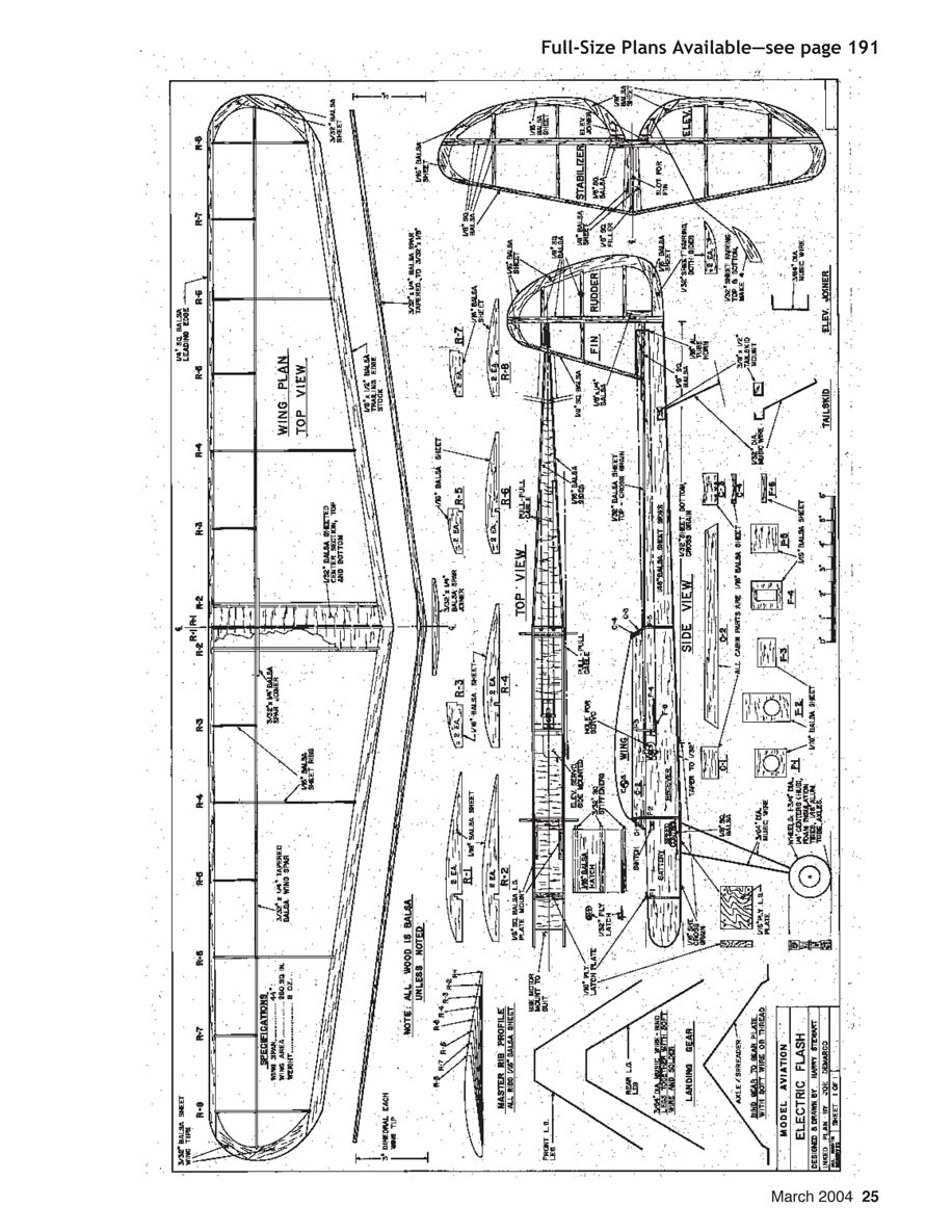
Before you are ready to cover, you need to fit the hinges. I used 3/32-inch-wide strips of Sig's Easy Hinge material. Use three hinges on the rudder and two on each side of the elevator. Cut the slots and trial-fit the hinges before covering to make sure that everything lines up properly. Now you are ready to cover.
After covering, you can glue hinges in place with cyanoacrylate. Because the model flies slowly, it takes more than the usual amount of control-surface movement. Before permanently attaching the control-surface hinges, make sure that you have at least 30° of movement to either side of neutral on the elevator and the rudder.
Fuselage
Cut the fuselage sides, formers, and cabin parts from 1/16-inch sheet. You could make one-piece fuselage sides, but by doing the fuselage sides and cabin sides in two pieces there is less wasted balsa. The formers and the front and back of the cabin are cut cross-grain.
The plans show a constant-width fuselage from F-2 forward. My first prototype had a pinched nose where F-1 was narrower than F-2. It all depends on the look that you want. For motors with narrow gearboxes, you can reduce the size of the front if you like that look; for motors with large spur gears, the wider front works better.
After you have cut out all of the pieces, glue the cabin sides to the fuselage sides. Mark the former locations and, using a square or a builder's triangle to ensure accuracy, glue the F-2 and F-5 formers to one side. If you are building the wide-nose version, you can also glue F-1 in place now; otherwise, leave it for later.
Now is a good time to discuss servo mounting. It is easier to install the servo mounts, F-3, F-4, and F-6 now, but if you want to wait to see how the model will balance, you can install them later. The servo mounts shown are for Hitec HS-50 or Cirrus CS-10 servos from Hobby People. If you will be using something different, you will have to modify these pieces to suit.
F-4 is for the rudder servo, and F-6 provides a secure mounting for the single servo mounting screw used. F-3 supports F-4/F-5 and keeps the fuselage sides from bowing when the elevator servo is installed.
There is a projection on top of the HS-50 and the CS-10. I mount the elevator servo through a matching hole in the left side of the fuselage and keep it in place with a block of balsa between the servo bottom and the fuselage side. A piece of tape keeps the block in place. Carefully matching the hole in the fuselage to the projection on the elevator servo keeps the servo from rotating, and the block wedges it in place and keeps it there. No mounting screws are necessary.
After you have glued the formers to one side of the fuselage, carefully add the other side. Make sure you attach this side even with the first, or you will introduce a twist into the fuselage.
The first three inches of the bottom sheeting aft of F-2 is 1/16-inch thick, cross-grain, of course. Attach this piece now to keep the fuselage square. You can sand this piece to blend into the rest of the 1/32-inch bottom sheeting later.
If you are using a narrowed F-1, install it now. Glue the gear plate in place along with its 1/8-inch square braces. If you narrowed the nose, trail-fit the gear plate and trim off the portion where the fuselage narrows. Finish sheeting the bottom front of the fuselage with another 3-inch piece of 1/16-inch sheet. Using 1/32-inch material, sheet the bottom back to F-5.
Install the front and rear cabin pieces: C-1 and C-3/C-4. Sand the bottom of C-1 so that the hatch will butt up to it. Make sure that the "V" in C-3/C-4 matches the dihedral angle of the wing because the wing sits on top of C-3/C-4 so that it can slide back easily if it gets "bumped."
Pull the fuselage sides together at the rear and glue them together, making sure that they join on the centerline. To get the straight-side taper from F-5 back to the tail I used a couple pieces of 1/2-inch square from F-5 to the tail and a couple rubber bands to squeeze the sides straight while I added the top and bottom 1/32-inch sheet to the rear of the fuselage. Not only do I like the straight-sided look, but it saves a little weight in top and bottom sheeting compared to a curved side.
Before you sheet all the way to the tail on the bottom, make the 1/32-inch music-wire tail skid and the 3/8 x 1/2-inch balsa mounting block, and glue them in place. The top sheeting on the rear of the fuselage only goes back to the stabilizer LE. The hinge line of the horizontal stabilizer is 1/4 inch ahead of the rear of the fuselage sides; trial-fit it now, and match the top sheeting to it exactly.
Make the hatch from 1/16-inch sheet and the hatch braces from 3/32-inch square. Make sure that the hatch braces extend back under C-1. Install the 1/16 plywood hatch plate at F-1. Make the latch from 1/32 plywood. Trial-fit these hatch pieces so that the hatch can be installed and removed easily.
All that is left is to drill the wing-hold-down dowel holes and install the dowels. Lightly sand the whole affair — remember to blend the 1/16-inch bottom sheeting into the 1/32-inch bottom sheeting — and it is ready for finishing.
Landing Gear/Wheels
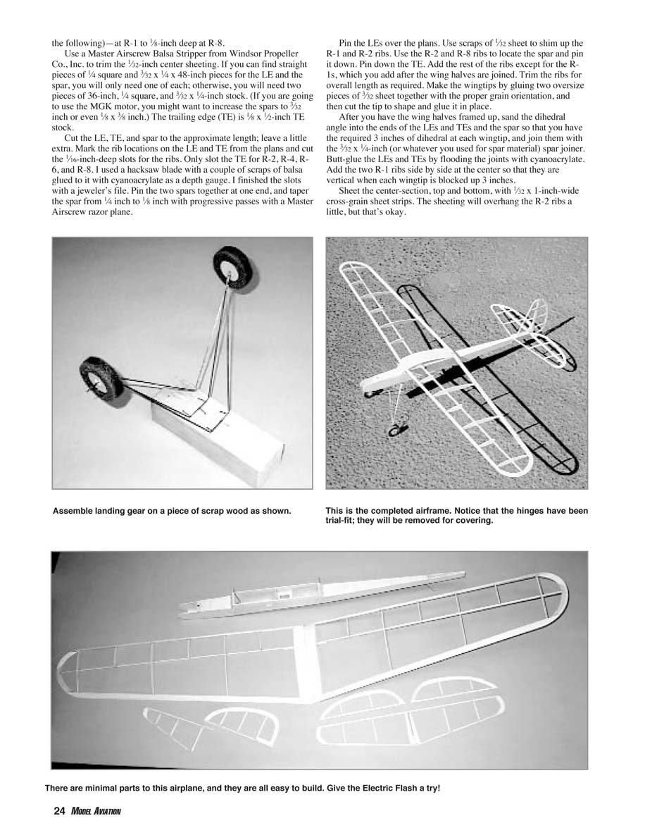
Bend the three pieces of the gear from 3/64-inch music wire. Temporarily fasten the front and rear gear legs 1 1/4 inches apart to a scrap block of wood. Bring the ends together, and bend approximately 5/8 inch of the rear gear leg so that it is parallel to the front gear leg. Bind the axle/spreader to the gear legs with soft copper wire, and solder them together.
After the fuselage is painted, you can gear the gear assembly to the gear plate with three small strips of soft copper wire. I made my wheels with 1/4-inch balsa centers and pipe-insulation foam tires with 1/16-inch-aluminum-tube wheel bearings. The wheels only weighed roughly a gram each.
The only tricky part is making the 1/4-inch balsa wheel round. I drew the circles with a compass and cut them as close to round as possible but slightly oversize. I drilled a hole through the centers using the compass center mark as a guide and bolted them together with a piece of 2-56 threaded rod, washers, and nuts. I chucked this in the drill press and used a sanding block at high rpm to sand them round.
When I was satisfied, I removed the 2-56 rod and installed a 5/16-inch-long piece of 1/16-inch-diameter aluminum tube in each wheel for a bearing. After a couple coats of paint, the wheels are ready for the pipe-insulation tires, which I glued to the balsa with cyanoacrylate. For wheel collars I used a plastic tube that came with a spray can that just slipped onto the 3/64-inch-diameter axle. A couple 1/8-inch pieces glued to the axle with cyanoacrylate have held the wheels in place nicely. If you don’t want to build your own wheels, you can buy a set of light wheels by Du-Bro at your local hobby shop.
Covering and Finishing
I covered both of the early prototypes with Litespan attached with Sig Stix-It. Today there are many more choices of lightweight covering materials available.
Since no fuel is involved, some of the dark flyers I’ve seen have their balsa parts left natural to save weight. I prefer a more finished look, so I painted the fuselage (and the wheels, as I already noted) with Sig dope. A couple coats of sanding sealer, a light sanding, and then a couple coats of color did the trick.
After you cover the tail surfaces—but before you permanently glue the hinges in place with cyanoacrylate—make sure that the control surfaces have plenty of free movement. You will need at least 30° in each direction. Also, it is probably easier to drill the holes in the elevator and rudder for the control horns, at the locations indicated on the plans, before they are attached to the fuselage.
Now all you have to do is attach the tail surfaces to the fuselage and you are ready to install the motor and radio equipment.
Equipment Installation and Control Linkages
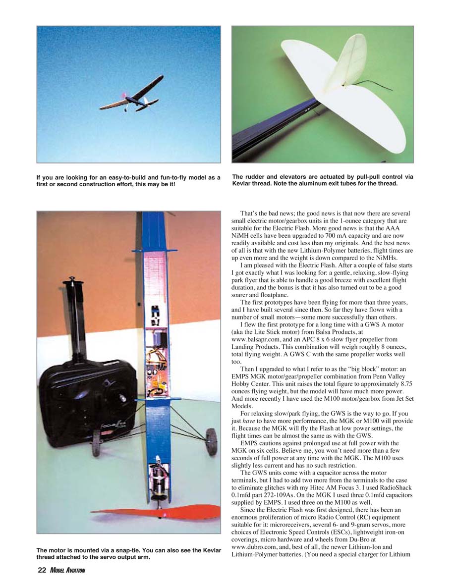
The motor unit you choose will determine the method of mounting required. I usually mount motors to a tray that fits between the cheek cowls. A drop of cyanoacrylate at the front and back of each side holds the tray in place. Don’t use too much adhesive in case you have to adjust the thrustline.
For the GWS motors I attach a piece of 3/16 balsa to each flat side of the gearbox with silicone adhesive, fit the unit between the cheek cowls, and attach it with a couple drops of cyanoacrylate on each side. On both of my models I mounted the motors with a slight amount of downthrust and right thrust—just enough of each so that I can see that the motor is not exactly zero-zero. Both prototypes have flown fine with no further adjustments.
The holes in F-1 and F-2 allow for the wiring to run from the motor to the speed control. The battery is located under the hatch between F-1 and F-2. The speed control is behind the battery, just in front of F-2. I used a Deans two-pin connector to join the battery and the speed control. I put the micro switch in the positive lead to the speed control. The receiver connection from the speed control goes back through F-2 to the throttle position on the receiver. The receiver, less its case, sits just behind F-2.
Since there is no vibration and I can’t imagine the Flash hitting anything very hard, I didn’t use any padding. The servos are mounted as explained in the fuselage section and plugged into the receiver.
For control linkage I employed a pull-pull system using Kevlar thread for the cables. Control horns are 1/16-inch-diameter aluminum tubes cut to the same length as the spread of the servo output arm. These are glued with cyanoacrylate into the control surfaces as close to the hinge line as possible at the locations shown on the plans.
The rudder cables exit the back of the cabin and run back over the top of the fuselage. The elevator cables run back along the left side of the fuselage. The Kevlar thread is looped under the servo-arm screw, under the servo arms, up through the servo arms, and back to the control horns. The threads run back to the control horns and are pulled through from each side, pulled tight, and wedged in place with a piece of 1/16-inch square balsa stick. A couple drops of cyanoacrylate keeps everything in place.
If you need to adjust the centering, loosen the servo-arm screw and slide the thread one way or the other. When you have what you want, retighten the servo-arm screw. Charge the batteries, and I think you are ready to fly.
Flying
If you’ve checked the center of gravity (CG), there are no apparent warps, the propeller turns the right way, up is up, down is down, right is right, left is left, and the battery is charged, you are ready to fly. If you have a smooth surface, the Flash will rise off ground. Over grass I usually hand launch. With full power and a gentle push, away it goes.
With the Hitec transmitter and the FMA speed control, there seems to be roughly seven “clicks,” or ratchet positions, of the throttle lever between off and full power. When you get to full power, more clicks on the throttle lever do you no good.
That’s okay, because once the Flash is flying I usually reduce power to roughly 50% unless I want it to climb. Even then it will climb nicely at less than full power. The whole idea, after all, is for the model to fly as slow as possible and to maximize the flight time.
The Flash is not aerobatic; it will loop, but that is about all. I just like watching it with the same fascination I remember from childhood, as it floats around almost silently with only the slight whirr from the gears noticeable from the ground.
The Flash will handle quite a breeze with the larger motors, but it is happiest with the smaller motors in calm air. If you find some rising air, this model will get way up there and climb at low power settings. When you are ready to land, reduce power until it descends.
Set up the approach, control the model's descent with the power until you can get it to where you want it to land, cut the power completely, glide down, and hold it off until it almost stops before it settles in. If you've done it right, the rollout will be approximately a foot on grass, roughly six feet on a ball diamond, and maybe two or three times that on pavement.
The FMA Direct Mini 5 speed control does not have a low-voltage cutoff for the motor, but I've never found this to be a problem. When the Flash won't climb any more at full power, it is time to land — but after 15–20 minutes of relaxing, fascinating flight, you won't mind at all.
Harry Stewart 220 Nihell St. Nevada City, CA 95959
Sources:
- FMA Direct
5716A Industry Ln. Frederick, MD 21704 www.fmadirect.com
- Hitec RCD, Inc.
12115 Paine St. Poway, CA 92064 www.hitecrcd.com
- Hobby People
18480 Bandilier Cir. Fountain Valley, CA 92728 www.hobbypeople.net
- Jet Set Models
117 2nd St. Lakewood, NJ 08701 www.jetsetairplanes.com
- Landing Products (APC)
1222 Harter Ave. Woodland, CA 95776 www.apcprop.com
- Penn Valley Hobby Center
837 W. Main St. Lansdale, PA 19446 www.pennvalleyhobbycenter.com
- Sig Manufacturing Company, Inc.
401-7 S. Front St. Montezuma, IA 50171 www.sigmfg.com
- Windsor Propeller Co., Inc. (Master Airscrew)
Box 250 Rancho Cordova, CA 95742 www.masterairscrew.com
Transcribed from original scans by AI. Minor OCR errors may remain.

