
Electric Flight Box
by Jim Young
Overview
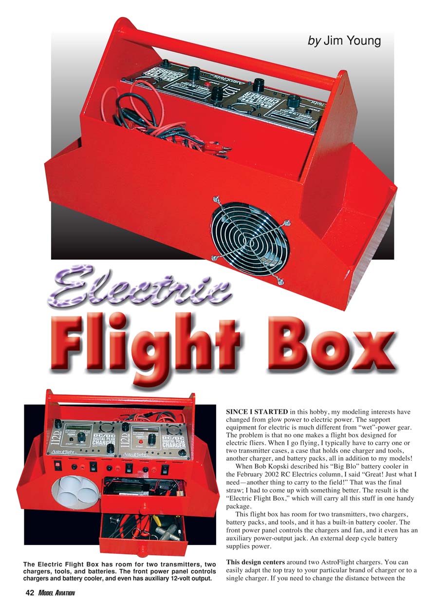
Since I started in this hobby, my modeling interests have changed from glow power to electric power. The support equipment for electric is much different from "wet"-power gear. The problem is that no one makes a flight box designed for electric fliers. When I go flying, I typically have to carry one or two transmitter cases, a case that holds one charger and tools, another charger, and battery packs — all in addition to my models!
When Bob Kopski described his "Big Blo" battery cooler in the February 2002 RC Electrics column, I said, "Great! Just what I need—another thing to carry to the field!" That was the final straw; I had to come up with something better. The result is the Electric Flight Box, which will carry all this stuff in one handy package.
This flight box has room for two transmitters, two chargers, battery packs, and tools, and it has a built-in battery cooler. The front power panel controls the chargers and fan, and it even has an auxiliary power-output jack. An external deep-cycle battery supplies power.
Features
- Holds two transmitters (end pockets are 3 inches deep and will accommodate most brands)
- Room for two chargers (design centers around two AstroFlight chargers)
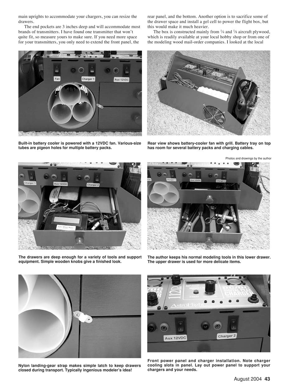
- Built-in 12 V battery cooler using a 4.75-inch PC cooling fan
- Front power panel with switches for each charger, fan, and an auxiliary output
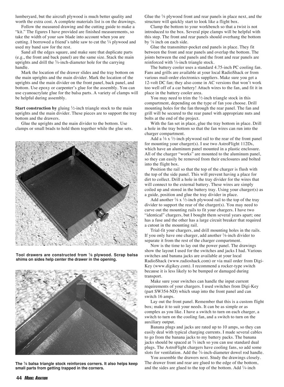
- Drawer storage for tools and batteries
- External deep-cycle battery powers the unit (option to install a gel cell at the cost of weight)
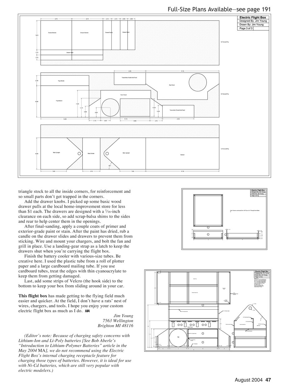
- Customizable tray spacing and drawer sizes to suit your chargers and packs
Materials and hardware
- 1/4-inch and 1/8-inch aircraft plywood (readily available at hobby shops or mail-order companies)
- 1/4-inch balsa triangle stock for corner reinforcement
- 1/8 x 1/2-inch plywood rails for charger mounting
- 1/4-inch plywood top tray
- 4.75-inch, 12 V DC PC cooling fan and grill (available at RadioShack or electronics suppliers)
- Rocker switches (I used Digi-Key part SW354-ND; rated to switch 16 A)
- Banana jacks and plugs (rated up to 10 A)
- Wood rod handle (3/4-inch diameter)
- 1/16-inch clearance on drawer sides (use scrap balsa shims to center)
- Landing-gear strap or adjustable nylon strap for drawer latches
- Velcro strips (hook side) for the box bottom
Construction
- Box skeleton
- Build the main box from 1/4- and 1/8-inch aircraft plywood. Glue the 1/8-inch plywood front and rear panels in place; the structure will quickly start to look like a flight box.
- Clamp the bottom to your workbench while gluing to avoid introducing a twist. Several pipe clamps are helpful.
- The front and rear panels should overhang the bottom by 1/8 inch on each side.
- End panels and corner reinforcement
- Glue the transmitter-pocket end panels in place; they fit between the front and rear panels and overlap the bottom.
- Reinforce joints between the end panels and the front and rear panels with 1/4-inch balsa triangle stock. The triangle stock also helps keep small parts from getting trapped in corners.
- Battery cooler compartment and fan
- The battery cooler uses a standard 4.75-inch PC cooling fan. Make sure you get a 12 V DC fan.
- You may need to trim the 1/4-inch triangle stock in the cooler compartment depending on the fan chosen.
- Drill mounting holes for the fan through the rear panel. The fan and grill will be secured to the rear panel with nuts and bolts at the end of the project.
- With the fan set in place, glue the tray bottom in place. Drill a hole in the tray bottom so the fan wires can run into the charger compartment.
- Charger mounting
- Add a 1/8 x 1/2-inch plywood rail to the rear of the front panel for mounting your charger(s). Position the rail so the top of the charger is flush with the top of the side panel to avoid dirt traps.
- Drill a hole in the tray divider for the wires that will connect to the external battery; these wires can be coiled and stored in the battery tray.
- Using your charger(s) as a guide, position and glue the tray divider in place.
- Add another 1/8 x 1/2-inch plywood rail to the top of the tray divider to support the rear of the charger(s). Carve out the mounting rails as needed to fit your chargers (e.g., for fuses or circuit-breaker housings).
- Trial-fit your chargers and drill mounting holes in the rails. If you only have one charger, add another 1/8-inch divider to separate it from the rest of the charger compartment.
- Top tray and battery pockets
- Cut the top tray out of 1/4-inch plywood. This tray will hold battery packs and charging cables.
- Make sure the battery pockets are sized to fit your packs. I used several different-size tubes glued to the tray to make pigeonholes for battery packs. Options include plastic plotter-paper tubes or large cardboard mailing tubes (treat cardboard edges with thin cyanoacrylate to prevent damage).
- Drawers
- Assemble the drawers: glue the drawer front and rear to the edge of the bottom; glue the sides to the top of the bottom. Add 1/4-inch balsa triangle stock to the inside corners for strength.
- Center the drawers with scrap balsa shims at the sides. Glue 1/8-inch plywood drawer faces in place and add simple wooden knobs (I used 5/8-inch dowel cutoffs).
- The drawers are designed with a 1/16-inch clearance on each side; use shims to help center them in the openings.
- Make latches to keep the drawers closed during transport. I used an adjustable nylon landing-gear strap with a snap that hooks over the wood handle. The strap holds well and is easy to remove at the field.
Power panel and wiring
- Lay out the power panel before final assembly. The layout shown in the drawings reflects the switches and jacks I used, but this is a custom flight box — make it to suit your needs.
- I recommend rocker-type switches because they are less likely to be bumped or damaged during transport.
- Make sure your switches can handle the input current requirements of your chargers. I used Digi-Key SW354-ND, which snap into the front panel and can switch 16 A.
- Typical layout:
- One switch per charger
- One switch for the cooling fan
- One switch for an auxiliary output
- Banana jacks for charger outputs; space them at 3/4 inch so you can use standard dual plugs
- Banana plugs and jacks are rated up to 10 A and can easily handle typical charging currents.
- Route wires from the banana jacks and the fan to the switches on the front panel. Connect the external battery wires to the power input terminal and secure all connections.
- Test the switches and chargers before loading your gear.
Handle, ventilation, and accessories
- Add a 3/4-inch-diameter wood rod handle.
- AstroFlight chargers have cooling fans; add slots or other ventilation for proper cooling.
- Finish the battery tray interior flat black to reduce glare from the cooling fan.
- Add strips of Velcro (hook side) to the bottom of the box to keep it from sliding around in your car.
Finishing
- Sand the entire box and apply the finish you prefer. I used a couple coats of polyurethane.
- After final sanding, apply a couple coats of primer and exterior-grade paint or stain.
- After paint has dried, rub a candle on the drawer slides and drawers to prevent sticking.
- Wire and mount your chargers, and bolt the fan and grill in place.
- Add the drawer knobs (I picked up basic wood drawer pulls at a home-improvement store for less than $1 each).
Final assembly and use
With everything assembled, the Electric Flight Box will carry your transmitters, chargers, battery packs, and tools in one convenient package and make transporting and charging your batteries much easier. At the field, you won't have a rats' nest of wires, chargers, and tools.
Tips
- If you need more space for transmitters, extend the front panel, the rear panel, and the bottom.
- If you choose to install an internal gel cell to power the flight box, remember it will add considerable weight.
- Be creative with battery-pocket inserts and tubes to accommodate various pack sizes.
- Treat cardboard tubes with thin cyanoacrylate at the edges to prevent damage.
Jim Young 7563 Wellington Brighton, MI 48116
Editor's note
Because of charging safety concerns with Lithium-Ion and Li-Poly batteries (see Bob Aberle's "Introduction to Lithium-Polymer Batteries," May 2004 MA), we do not recommend using the Electric Flight Box's internal charging receptacle feature for charging those types of batteries. However, it is ideal for use with Ni-Cd batteries, which are still very popular with electric modelers.
Transcribed from original scans by AI. Minor OCR errors may remain.

