
Electric Zephyr
Weldon Smith
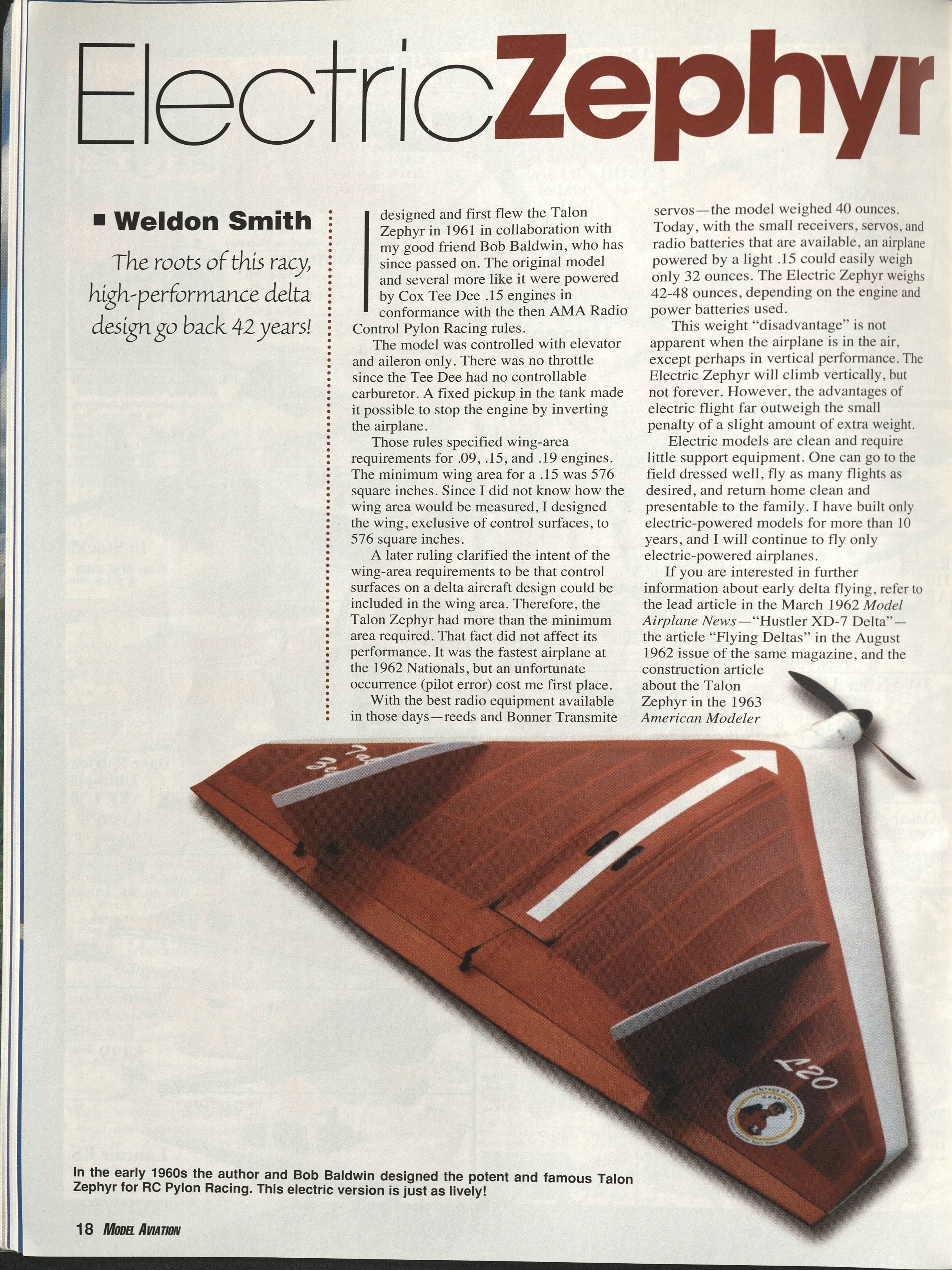
The roots of this racy, high-performance delta design go back 42 years!
I designed and first flew the Talon Zephyr in 1961 in collaboration with my good friend Bob Baldwin, who has since passed on. The original model and several more like it were powered by Cox Tee Dee .15 engines in conformance with the then AMA Radio Control Pylon Racing rules.
The model was controlled with elevator and aileron only. There was no throttle since the Tee Dee had no controllable carburetor. A fixed pickup in the tank made it possible to stop the engine by inverting the airplane.
Those rules specified wing-area requirements for .09, .15, and .19 engines. The minimum wing area for a .15 was 576 square inches. Since I did not know how the wing area would be measured, I designed the wing, exclusive of control surfaces, to 576 square inches.
A later ruling clarified the intent of the wing-area requirements to be that control surfaces on a delta aircraft design could be included in the wing area. Therefore, the Talon Zephyr had more than the minimum area required. That fact did not affect its performance. It was the fastest airplane at the 1962 Nationals, but an unfortunate occurrence (pilot error) cost me first place.
With the best radio equipment available in those days—reeds and Bonner transmitter servos—the model weighed 40 ounces. Today, with the small receivers, servos, and radio batteries that are available, an airplane powered by a light .15 could easily weigh only 32 ounces. The Electric Zephyr weighs 42–48 ounces, depending on the motor and power batteries used.
This weight "disadvantage" is not apparent when the airplane is in the air, except perhaps in vertical performance. The Electric Zephyr will climb vertically, but not forever. However, the advantages of electric flight far outweigh the small penalty of a slight amount of extra weight.
Electric models are clean and require little support equipment. One can go to the field dressed well, fly as many flights as desired, and return home clean and presentable to the family. I have built only electric-powered models for more than 10 years, and I will continue to fly only electric-powered airplanes.
If you are interested in further information about early delta flying, refer to the lead article in the March 1962 Model Airplane News—"Hustler XD-7 Delta"—the article "Flying Deltas" in the August 1962 issue of the same magazine, and the construction article about the Talon Zephyr in the 1963 American Modeler Annual. You can order copies of these articles from the AMA library.
CONSTRUCTION
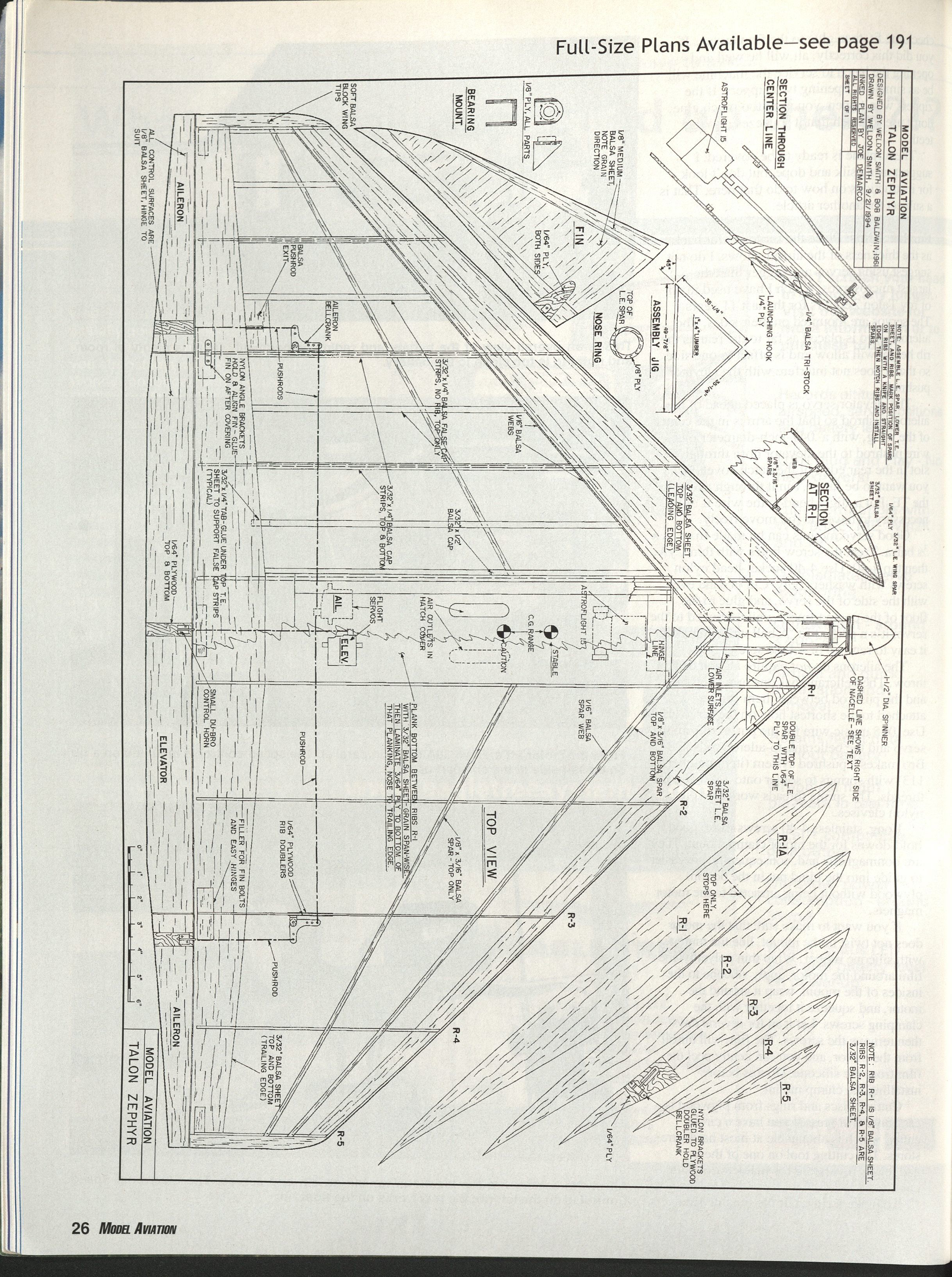
Make a fixture from straight 1 x 2-inch wood using dimensions on the plans. Buy an extra piece of 1 x 2-inch wood; you will need it later. Cut the trailing edge (TE) of the fixture, measure the 45°, subtract it from the leading edge (LE) pieces dimensioned on the plans, and cut the LEs to that length. Bevel the top of the TE to match the upward curve of the ribs, then assemble. Notch the LE pieces for the ribs. The notches should be centered on each rib position and approximately 3/16 inch to each side. Wax the top of the fixture with paraffin. All sheet balsa is 3/32, 4- to 6-pound-density stock except where noted on the plans.
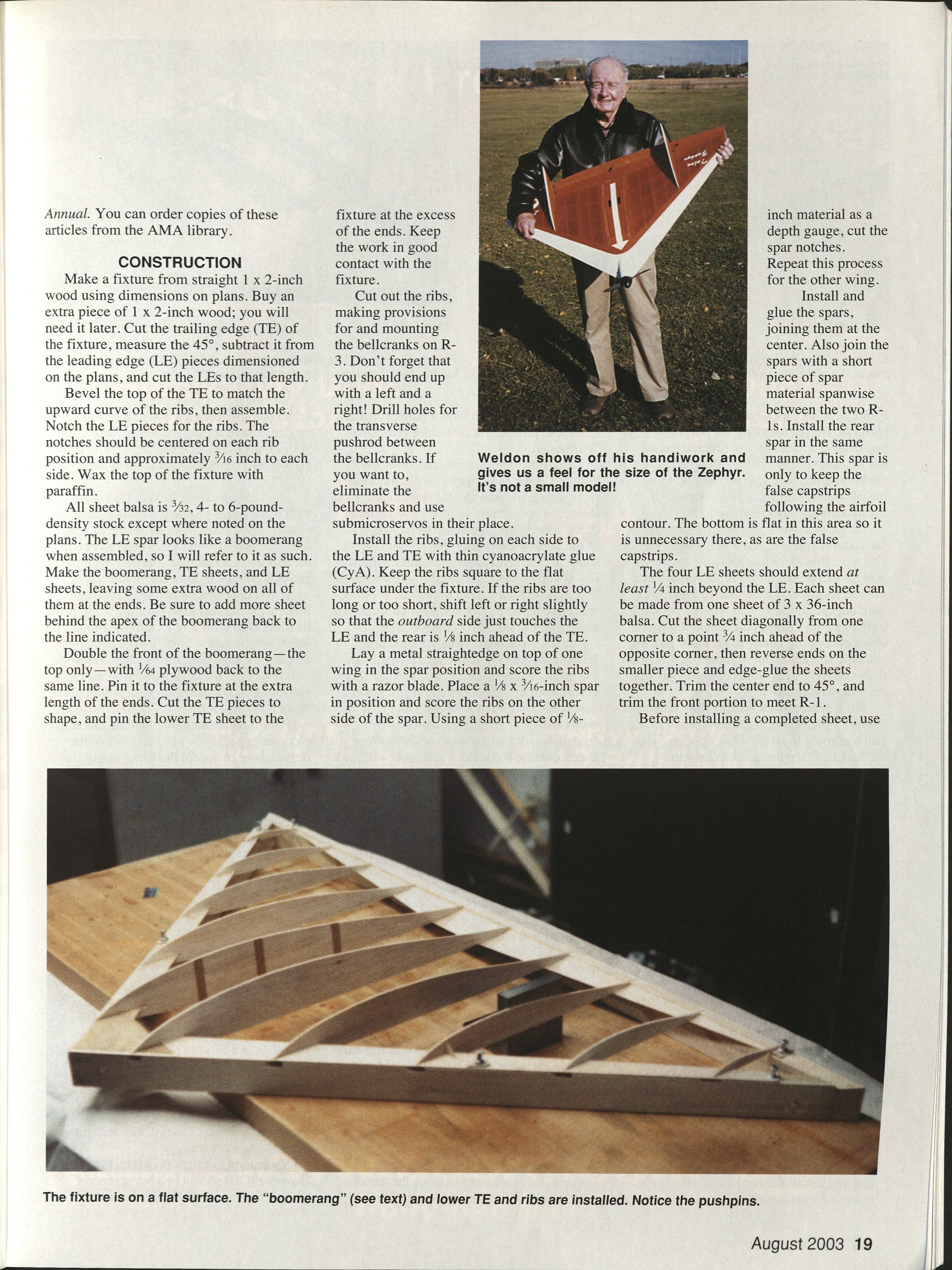
The LE spar looks like a boomerang when assembled, so I will refer to it as such. Make the boomerang, TE sheets, and LE sheets, leaving some extra wood on all of them at the ends. Be sure to add more sheet behind the apex of the boomerang back to the line indicated. Double the front of the boomerang—the top only—with 1/64 plywood back to the same line. Pin it to the fixture at the extra length of the ends. Cut the TE pieces to shape, and pin the lower TE sheet to the fixture at the excess of the ends. Keep the work in good contact with the fixture.
Cut out the ribs, making provisions for and mounting the bellcranks on R-3. Don't forget that you should end up with a left and a right! Drill holes for the transverse pushrod between the bellcranks. If you want to, eliminate the bellcranks and use submicro servos in their place.
Install the ribs, gluing on each side to the LE and TE with thin cyanoacrylate glue (CyA). Keep the ribs square to the flat surface under the fixture. If the ribs are too long or too short, shift left or right slightly so that the outboard side just touches the LE and the rear is 1/8 inch ahead of the TE.
Lay a metal straightedge on top of one wing in the spar position and score the ribs with a razor blade. Place a 1/8 x 3/16-inch spar in position and score the ribs on the other side of the spar. Using a short piece of 1/8-inch material as a depth gauge, cut the spar notches. Repeat this process for the other wing.
Install and glue the spars, joining them at the center. Also join the spars with a short piece of spar material spanwise between the two R-1s. Install the rear spar in the same manner. This spar is only to keep the false capstrips following the airfoil contour. The bottom is flat in this area so it is unnecessary there, as are the false capstrips.
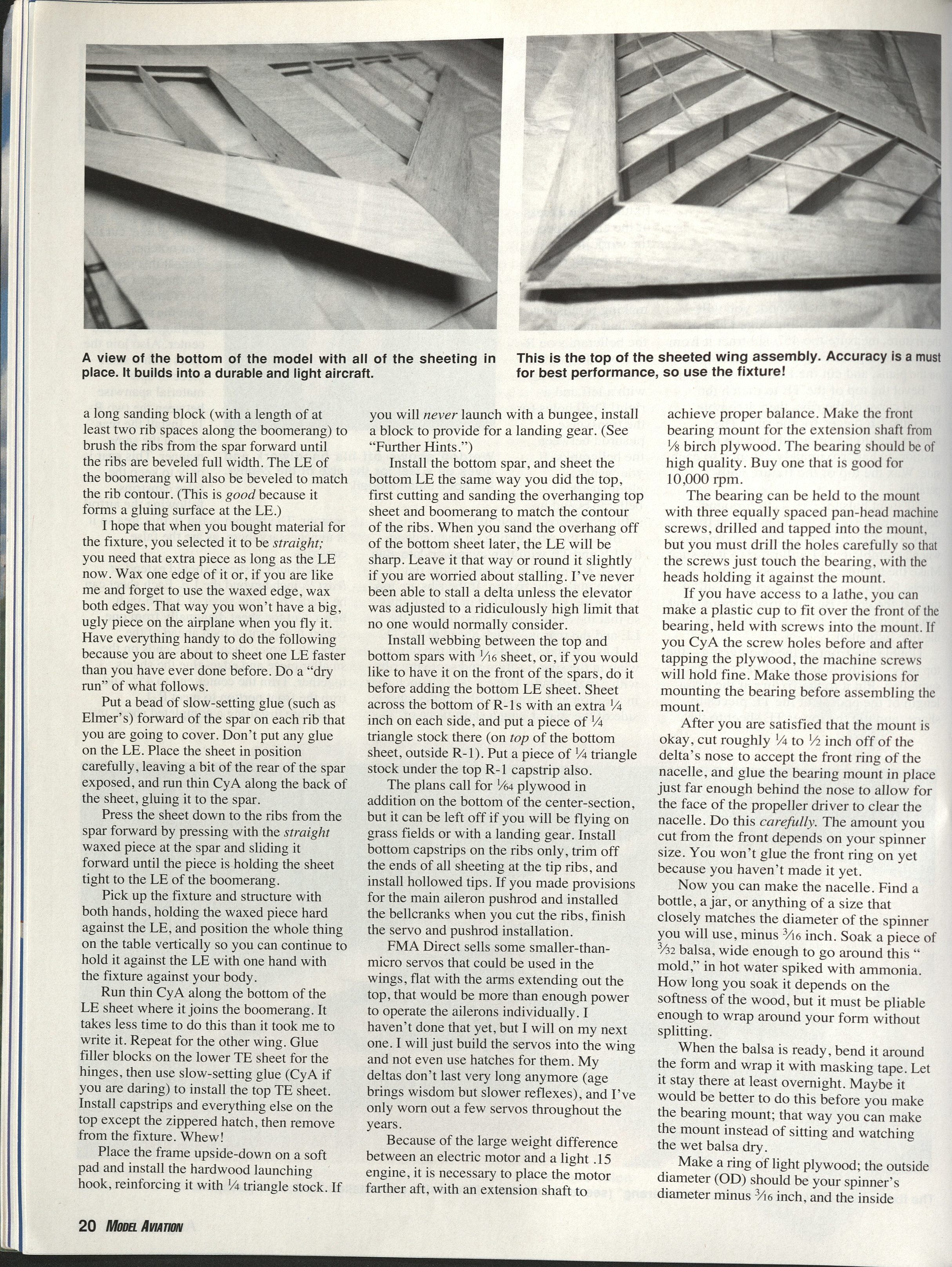
The four LE sheets should extend at least 1/4 inch beyond the LE. Each sheet can be made from one sheet of 3 x 36-inch balsa. Cut the sheet diagonally from one corner to a point 3/4 inch ahead of the opposite corner, then reverse ends on the smaller piece and edge-glue the sheets together. Trim the center end to 45°, and trim the front portion to meet R-1.
Before installing a completed sheet, use a long sanding block (with a length of at least two rib spaces along the boomerang) to brush the ribs from the spar forward until the ribs are beveled full width. The LE of the boomerang will also be beveled to match the rib contour. (This is good because it forms a gluing surface at the LE.)
I hope that when you bought material for the fixture, you selected it to be straight; you need that extra piece as long as the LE now. Wax one edge of it or, if you are like me and forget to use the waxed edge, wax both edges. That way you won't have a big, ugly piece on the airplane when you fly it. Have everything handy to do the following because you are about to sheet one LE faster than you have ever done before. Do a "dry run" of what follows.
Put a bead of slow-setting glue (such as Elmer's) forward of the spar on each rib that you are going to cover. Don't put any glue on the LE. Place the sheet in position carefully, leaving a bit of the rear of the spar exposed, and run thin CyA along the back of the sheet, gluing it to the spar.
Press the sheet down to the ribs from the spar forward by pressing with the straight waxed piece at the spar and sliding it forward until the piece is holding the sheet tight to the LE of the boomerang.
Pick up the fixture and structure with both hands, holding the waxed piece hard against the LE, and position the whole thing on the table vertically so you can continue to hold it against the LE with one hand with the fixture against your body.
Run thin CyA along the bottom of the LE sheet where it joins the boomerang. It takes less time to do this than it took me to write it. Repeat for the other wing. Glue filler blocks on the lower TE sheet for the hinges, then use slow-setting glue (CyA if you are daring) to install the top TE sheet. Install capstrips and everything else on the top except the zippered hatch, then remove from the fixture.
Place the frame upside-down on a soft pad and install the hardwood launching hook, reinforcing it with 1/4 triangle stock. If you will never launch with a bungee, install a block to provide for a landing gear. (See "Further Hints.")
Install the bottom spar, and sheet the bottom LE the same way you did the top, first cutting and sanding the overhanging top sheet and boomerang to match the contour of the ribs. When you sand the overhang off of the bottom sheet later, the LE will be sharp. Leave it that way or round it slightly if you are worried about stalling. I've never been able to stall a delta unless the elevator was adjusted to a ridiculously high limit that no one would normally consider.
Install webbing between the top and bottom spars with 1/16 sheet, or, if you would like to have it on the front of the spars, do it before adding the bottom LE sheet. Sheet across the bottom of R-1s with an extra 1/4 inch on each side, and put a piece of 1/4 triangle stock there (on top of the bottom sheet, outside R-1). Put a piece of 1/4 triangle stock under the top R-1 capstrip also.
The plans call for 1/64 plywood in addition on the bottom of the center-section, but it can be left off if you will be flying on grass fields or with a landing gear. Install bottom capstrips on the ribs only, trim off the ends of all sheeting at the tip ribs, and install hollowed tips. If you made provisions for the main aileron pushrod and installed the bellcranks when you cut the ribs, finish the servo and pushrod installation.
FMA Direct sells some smaller-than-micro servos that could be used in the wings, flat with the arms extending out the top, that would be more than enough power to operate the ailerons individually. I haven't done that yet, but I will on my next one. I will just build the servos into the wing and not even use hatches for them. My deltas don't last very long anymore (age brings wisdom but slower reflexes), and I've only worn out a few servos throughout the years.
Because of the large weight difference between an electric motor and a light .15 engine, it is necessary to place the motor farther aft, with an extension shaft to achieve proper balance. Make the front bearing mount for the extension shaft from 1/8 birch plywood. The bearing should be of high quality. Buy one that is good for 10,000 rpm.
The bearing can be held to the mount with three equally spaced pan-head machine screws, drilled and tapped into the mount, but you must drill the holes carefully so that the screws just touch the bearing, with the heads holding it against the mount.
If you have access to a lathe, you can make a plastic cup to fit over the front of the bearing, held with screws into the mount. If you CyA the screw holes before and after tapping the plywood, the machine screws will hold fine. Make those provisions for mounting the bearing before assembling the mount.
After you are satisfied that the mount is okay, cut roughly 1/4 to 1/2 inch off of the delta's nose to accept the front ring of the nacelle, and glue the bearing mount in place just far enough behind the nose to allow for the face of the propeller driver to clear the nacelle. Do this carefully. The amount you cut from the front depends on your spinner size. You won't glue the front ring on yet because you haven't made it yet.
Now you can make the nacelle. Find a bottle, a jar, or anything of a size that closely matches the diameter of the spinner you will use, minus 3/16 inch. Soak a piece of 3/32 balsa, wide enough to go around this "mold," in hot water spiked with ammonia. How long you soak it depends on the softness of the wood, but it must be pliable enough to wrap around your form without splitting.
When the balsa is ready, bend it around the form and wrap it with masking tape. Let it stay there at least overnight. Maybe it would be better to do this before you make the bearing mount; that way you can make the mount instead of sitting and watching the wet balsa dry.
Make a ring of light plywood; the outside diameter (OD) should be your spinner's diameter minus 3/16 inch, and the inside diameter (ID) should be the propeller driver diameter.
The bottom of the airfoil is at 1° to the chord line. The thrustline is parallel to the chord line. Therefore, you must make a block, beveled 1° on the bottom, of a size dependent on the motor you use, to get the motor shaft up to the height of the position shown on the plans, with the shaft parallel to the chord line. Make the size so that you can glue the bottom of a motor clamp of birch plywood and balsa triangle stock above it and have the shaft at the right height.
Now that the motor is mounted with the shaft through the front bearing, slide the plywood disc, with the plywood ring around it, onto the shaft, back to the front of the delta, and glue the ring in place—not the disc. Do this carefully, and later the spinner will match the front of the nacelle perfectly.
Shape the balsa cylinder—the nacelle—to meet the LE sheeting, and glue it in place. There is access to the front shaft bearing through the nacelle opening. The new Electric Zephyr is almost ready to cover now, but I put the hatch on next because I still use silk and dope, and it is easier for me to have the airframe complete before covering. You may want to do it differently, but I normally cover with that good, old stuff.
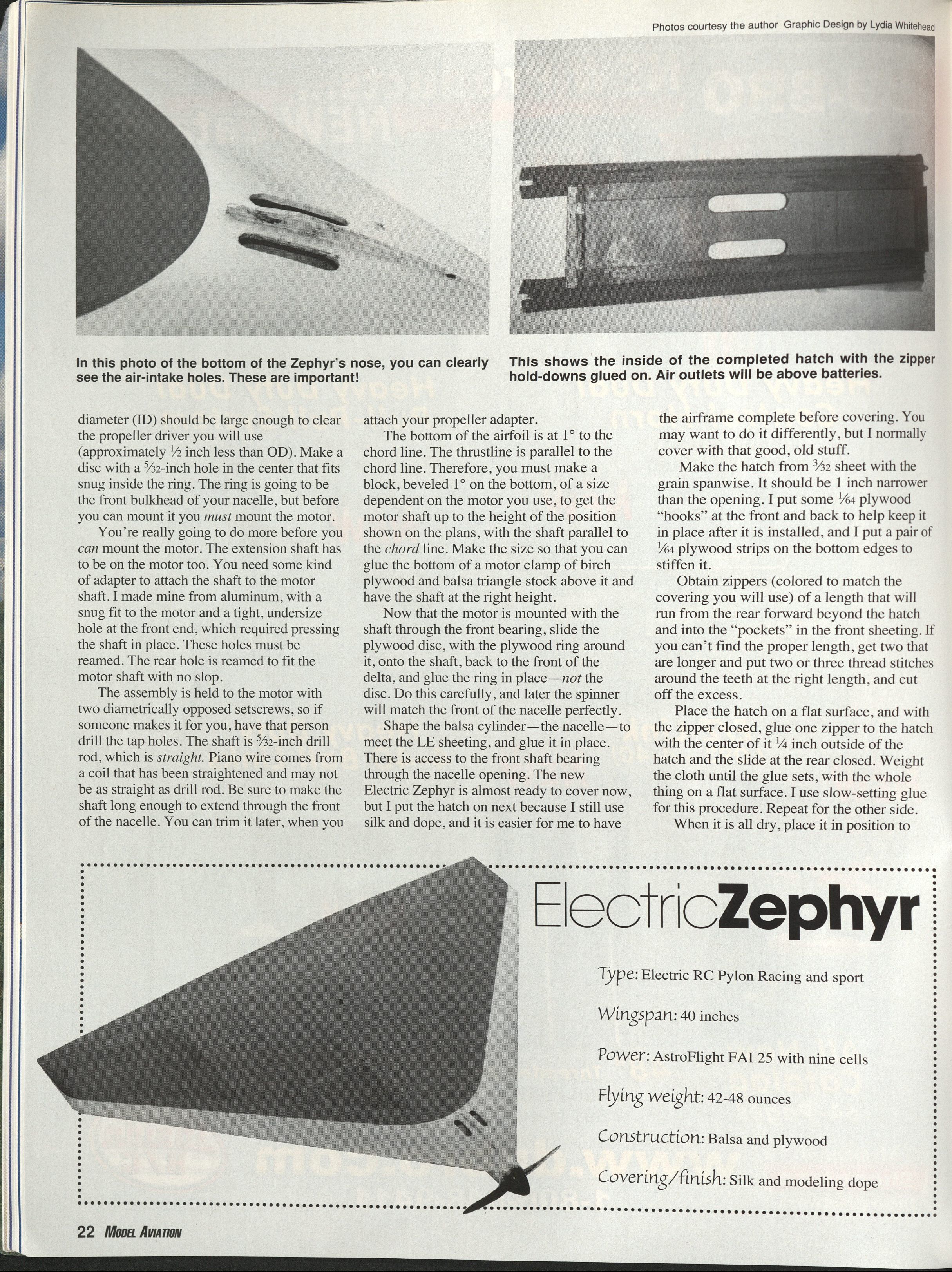
Make the hatch from 3/32 sheet with the grain spanwise. It should be 1 inch narrower than the opening. I put some 1/64 plywood "hooks" at the front and back to help keep it in place after it is installed, and I put a pair of 1/64 plywood strips on the bottom edges to stiffen it.
Obtain zippers (colored to match the covering you will use) of a length that will run from the rear forward beyond the hatch and into the "pockets" in the front sheeting. If you can't find the proper length, get two that are longer and put two or three thread stitches around the teeth at the right length, and cut off the excess.
Place the hatch on a flat surface, and with the zipper closed, glue one zipper to the hatch with the center of it 1/4 inch outside of the hatch and the slide at the rear closed. Weight the cloth until the glue sets, with the whole thing on a flat surface. I use slow-setting glue for this procedure. Repeat for the other side.
When it is all dry, place it in position to check the fit, then glue to the framework. If you did this correctly, all will be well and opening the hatch to service the machine will be as simple as opening two zippers. If the zippers won't open, you used too much glue; don't use so much that it squeezes into the teeth.
The airplane is ready to be covered. I suggest using silk and dope, but don't look for instructions on how to do that here. That is a subject for another article.
FURTHER HINTS
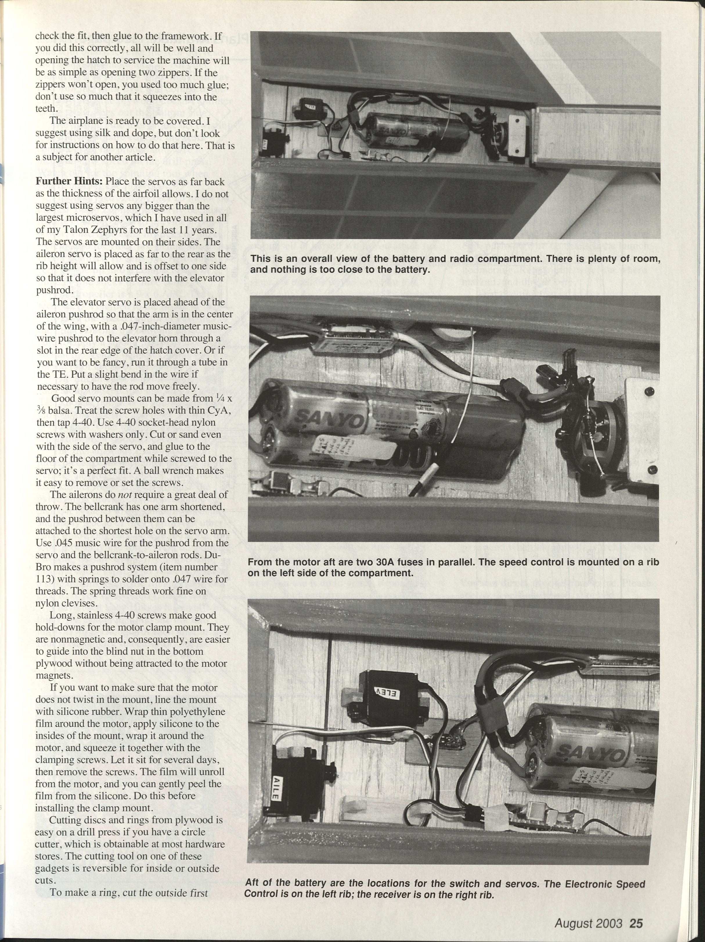
Place the servos as far back as the thickness of the airfoil allows. I do not suggest using servos any bigger than the largest microservos, which I have used in all of my Talon Zephyrs for the last 11 years. The servos are mounted on their sides. The aileron servo is placed as far to the rear as the rib height will allow and is offset to one side so that it does not interfere with the elevator pushrod.
The elevator servo is placed ahead of the aileron pushrod so that the arm is in the center of the wing, with a .047-inch-diameter music-wire pushrod to the elevator horn through a slot in the rear edge of the hatch cover. Or, if you want to be fancy, run it through a tube in the TE. Put a slight bend in the wire if necessary to have the rod move freely.
Good servo mounts can be made from 1/4 x 3/8 balsa. Treat the screw holes with thin CyA, then tap 4-40. Use 4-40 socket-head nylon screws with washers only. Cut or sand even with the side of the servo, and glue to the floor of the compartment while screwed to the servo; it's a perfect fit. A ball wrench makes it easy to remove or set the screws.
The ailerons do not require a great deal of throw. The bellcrank has one arm shortened, and the pushrod between them can be attached to the shortest hole on the servo arm. Use .045 music wire for the pushrod from the servo and the bellcrank-to-aileron rods. DuBro makes a pushrod system (item number 113) with springs to solder onto .047 wire for threads. The spring threads work fine on nylon clevises.
Long, stainless 4-40 screws make good hold-downs for the motor clamp mount. They are nonmagnetic and, consequently, are easier to guide into the blind nut in the bottom plywood without being attracted to the motor magnets.
If you want to make sure that the motor does not twist in the mount, line the mount with silicone rubber. Wrap thin polyethylene film around the motor, apply silicone to the inside of the mount, wrap it around the motor, and squeeze it together with the clamping screws. Let it sit for several days, then remove the screws. The film will unroll from the motor, and you can gently peel the film from the silicone. Do this before installing the clamp mount.
Cutting discs and rings from plywood is easy on a drill press if you have a circle cutter, which is obtainable at most hardware stores. The cutting tool on one of these gadgets is reversible for inside or outside cuts.
To make a ring, cut the outside first, then fasten the disc to a piece of 1-inch pine with brads, reverse the tool bit, reset the radius, and make the cut. All cuts should only be slightly more than halfway, then turn the work over and complete the cut. This way the plywood doesn't splinter as the tool comes out the bottom side.
"Reversing" the tool bit means twisting it so that the square edge of the work comes out on the proper side. Use a medium-slow speed on the drill press. Watch out for the spinning tool when you're holding the plywood.
I used an AstroFlight FAI 25 motor on the last Talon Zephyr, primarily because it requires only 10 cells to provide great power. I use nine cells in sticks of three, Velcroed to the floor just behind the motor. I have not tried 10 cells yet. Also, nine cells divide up into a compact pack of three in-line sticks of three cells.
The propeller is a 9 x 6 APC. The receiver is Velcroed to the inside of one R-1 rib, and the speed control is Velcroed to the other. During the building process be sure to apply a smooth finish to these areas so that the Velcro will stick. The switch is on the floor ahead of the servos.
The full antenna is in one wing in a tube along one top spar and around into the TE. Another option is to cut the antenna close to the receiver and place a connector at the break. Glue the long piece into the wing, making a smooth bend at the tip.
The fins are made from 1/8 balsa, in three pieces, with the center piece's grain vertical and the outer pieces' grain more or less parallel to the edge. If you use the nylon angle brackets as shown on the plans, it is easier to align the fin vertically and apply a bead of Sig, Testors, or other balsa glue along each side of the wing-fin joint. You only use those glues on a doped covering or bare wood. If you like film, install a wider capstrip so you can remove a strip of film where the fin attaches, then glue it. If you're in a hurry, use CyA!
I have used Easy Hinges fastened with thin CyA, except that they are cut into thirds. Two is enough for each aileron, and four is enough for the elevator. Set the elevator somewhat below an extension of the bottom surface of the wing, but not as low as "level." Line up the ailerons with the elevator. (You did check the elevator for warps, didn't you?)
Launching: There are two ways to use a catapult launch, and either method requires roughly 10 feet of 3/8-inch-diameter surgical tubing tied to 10 feet of nylon cord with a loop on the far end. Attach the tubing to the ground with a sturdy stake; I tightly tie the tubing to 18 inches of steel rod.
If you have a helper, have him or her grasp the leading edges outside the fins from above and hold the delta out in front of himself or herself while you attach the loop (a key ring works fine). Guide your assistant backward downwind 15 or 20 steps (or until he or she says that it is getting too hard to step back any farther).
You should have turned on the radio and made all checks before attaching the ring. Hold approximately half up-elevator and give him or her a prearranged signal to release. Your helper merely has to raise his or her hands, and the airplane is off and flying.
The other launching method is to use a pedal launcher. Hold half elevator again, or the airplane will hit the ground near (or on) the stake. Never open the throttle until the line has fallen from the model. Regardless of whether or not you think the launch is weak, don't help the speed with throttle. The propeller will snarl the line, and you will have a nasty repair to accomplish.
A streamer of silk tied near the launching loop helps you know when the line falls. When that happens, the airplane should have enough speed to fly some distance without power, so open the throttle gently and fly it. The model has flown well with a Speed 600 motor, so what you use is up to you; it depends on what sort of performance you want to achieve: trainerlike or tiger-by-the-tail.
Landing Gear: If you must have a landing gear, make it from 3/32-inch wire, including the nose gear. Make that with two turns around a 1/4-inch rod and of a length that accommodates propeller clearance and your takeoff surface. Place the rear gears no farther back than 12 inches ahead of the TE hinge line, with the strut at R-2 and the torsion bar going to R-1. Make the strut length so that the airplane will sit level.
To mount the nose gear, drill a 3/32-inch hole through the launch hook, 1/4 inch behind where the front extension shaft bearing plywood plate will be. Do this before you install the hook (or block), and keep the hole square and centered.
Later, extend that hole up through the boomerang. Place an eyelet on top of the coil, push the wire up through the launch hook, and mark the wire 1/4 inch above the boomerang. Remove the wire, cut where marked, and thread 2-56.
That evening, put all of the wires in your kitchen oven at the highest temperature it will achieve. Leave them alone for an hour, shut off the oven and leave the door closed, and go to bed. In the morning the wires will resist bending much more than if they were not heat-treated. Install the gear using a nylon lock nut to hold the nose gear in place (with the extension shaft removed).
To steer the nose gear, solder a steering arm to the eyelet, install another servo, and make a pushrod from 1/32-inch wire guided through small nylon tubing. If you fly from a hard surface, Williams Bros. makes nice, slim wheels that are adequate without producing much drag.
Remember one thing on takeoff: forcing the model off without flying speed will result in a torque roll into the ground. Similarly, adding a great deal of power to go around when the aircraft is well slowed on approach will give the same result.
You can direct any questions to me. Please enclose a self-addressed, stamped envelope for a reply.
MA
Weldon Smith 311 Wooded Knoll Dr. Cary IL 60010
Transcribed from original scans by AI. Minor OCR errors may remain.

