

Electrics - 2008/08
Approach Engineering is under scale guru Dr. Tim's care
Also included in this column:
- XPS rescues the Evo radio
- Toledo Weak Signals' show
TAKING OFF
I just got back from the Toledo Weak Signals show and am still filtering through all the photos and such. I had planned to do more coverage of it this month, but I landed in the hospital the day after I got back. So everything is running a little behind, and I don't want to be late with the deadline; you know how those editors will take the stick to us. I'll fill in with some specifics in the next few columns as space permits. You can see my photos of the show online.
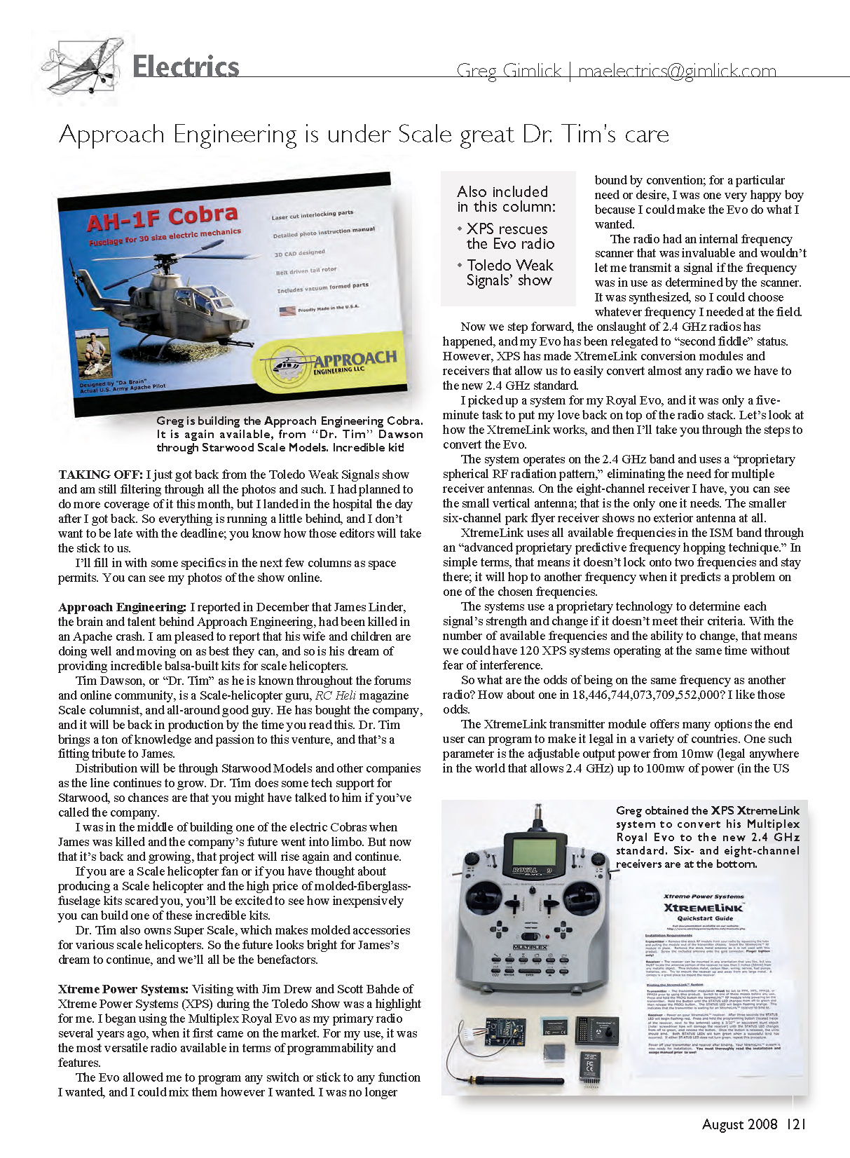
Approach Engineering
I reported in December that James Linder, the brain and talent behind Approach Engineering, had been killed in an Apache crash. I am pleased to report that his wife and children are doing well and moving on as best they can, and so is his dream of providing incredible balsa-built kits for scale helicopters.
Tim Dawson, or "Dr. Tim" as he is known throughout the forums and online community, is a scale-helicopter guru, RC Heli magazine scale columnist, and all-around good guy. He has bought the company, and it will be back in production by the time you read this. Dr. Tim brings a ton of knowledge and passion to this venture, and that's a fitting tribute to James.
Distribution will be through Starwood Models and other companies as the line continues to grow. Dr. Tim does some tech support for Starwood, so chances are that you might have talked to him if you've called the company.
I was in the middle of building one of the electric Cobras when James was killed and the company's future went into limbo. But now that it's back and growing, that project will rise again and continue.
If you are a scale-helicopter fan or if you have thought about producing a scale helicopter and the high price of molded-fiberglass-fuselage kits scared you, you'll be excited to see how inexpensively you can build one of these incredible kits.
Dr. Tim also owns Super Scale, which makes molded accessories for various scale helicopters. So the future looks bright for James's dream to continue, and we'll all be the benefactors.
Xtreme Power Systems
Visiting with Jim Drew and Scott Bahde of Xtreme Power Systems (XPS) during the Toledo show was a highlight for me. I began using the Multiplex Royal Evo as my primary radio several years ago, when it first came on the market. For my use, it was the most versatile radio available in terms of programmability and features. The Evo allowed me to program any switch or stick to any function I wanted, and I could mix them however I wanted. I was no longer bound by convention; for a particular need or desire, I was one very happy boy because I could make the Evo do what I wanted.
The radio had an internal frequency scanner that was invaluable and wouldn't let me transmit a signal if the frequency was in use as determined by the scanner. It was synthesized, so I could choose whatever frequency I needed at the field.
Now we step forward: the onslaught of 2.4 GHz radios has happened, and my Evo has been relegated to "second fiddle" status. However, XPS has made XtremeLink conversion modules and receivers that allow us to easily convert almost any radio we have to the new 2.4 GHz standard.
I picked up a system for my Royal Evo, and it was only a five-minute task to put my love back on top of the radio stack. Here's how the XtremeLink works, and then the steps to convert the Evo.
The system operates on the 2.4 GHz band and uses a "proprietary spherical RF radiation pattern," eliminating the need for multiple receiver antennas. On the eight-channel receiver I have, you can see the small vertical antenna; that is the only one it needs. The smaller six-channel park-flyer receiver shows no exterior antenna at all.
XtremeLink uses all available frequencies in the ISM band through an "advanced proprietary predictive frequency-hopping technique." In simple terms, that means it doesn't lock onto two frequencies and stay there; it will hop to another frequency when it predicts a problem on one of the chosen frequencies.
The systems use proprietary technology to determine each signal's strength and change it if it doesn't meet their criteria. With the number of available frequencies and the ability to change, that means we could have 120 XPS systems operating at the same time without fear of interference.
So what are the odds of being on the same frequency as another radio? How about one in 18,446,744,073,709,552,000? I like those odds.
The XtremeLink transmitter module offers many options the end user can program to make it legal in a variety of countries. One such parameter is the adjustable output power from 10 mW (legal anywhere in the world that allows 2.4 GHz) up to 100 mW of power (in the U.S. and select other countries). The module also uses less than 90 mA, which increases your transmitter battery life roughly five times compared to 72 MHz RF modules.
XPS uses bidirectional communication between the transmitter module and the receiver. Because of this, and its 65,536 (16-bit) system, there will eventually be telemetry options and possibly even video and audio features in the near future. The XtremeLink's features are as follows.
- Radio speed (effective throughput): 256 kbps
- Frequency hopping: Yes (only when interference is predicted)
- Specified range: 5 miles
- Resolution: 65,536 (16 bits)
- Number of systems that can be in use simultaneously: 120
- Integrated single antenna: Yes
- Real-time, built-in telemetry interface: Yes
- Bidirectional communications: Yes
- Receivers available or pending (number of channels): 3, 6, 8, 10, 12, 16
- Module pricing (MSRP of transmitter module/receiver): $149–$219
- Receiver pricing (MSRP of receivers): $59–$149
- Latency (measured from stick input to receiver output): 2 ms to 1 frame
- Fail-safe programmable for each channel: Yes
- Operating voltage range: 3.5–30.0 V
- Product warranty: Lifetime
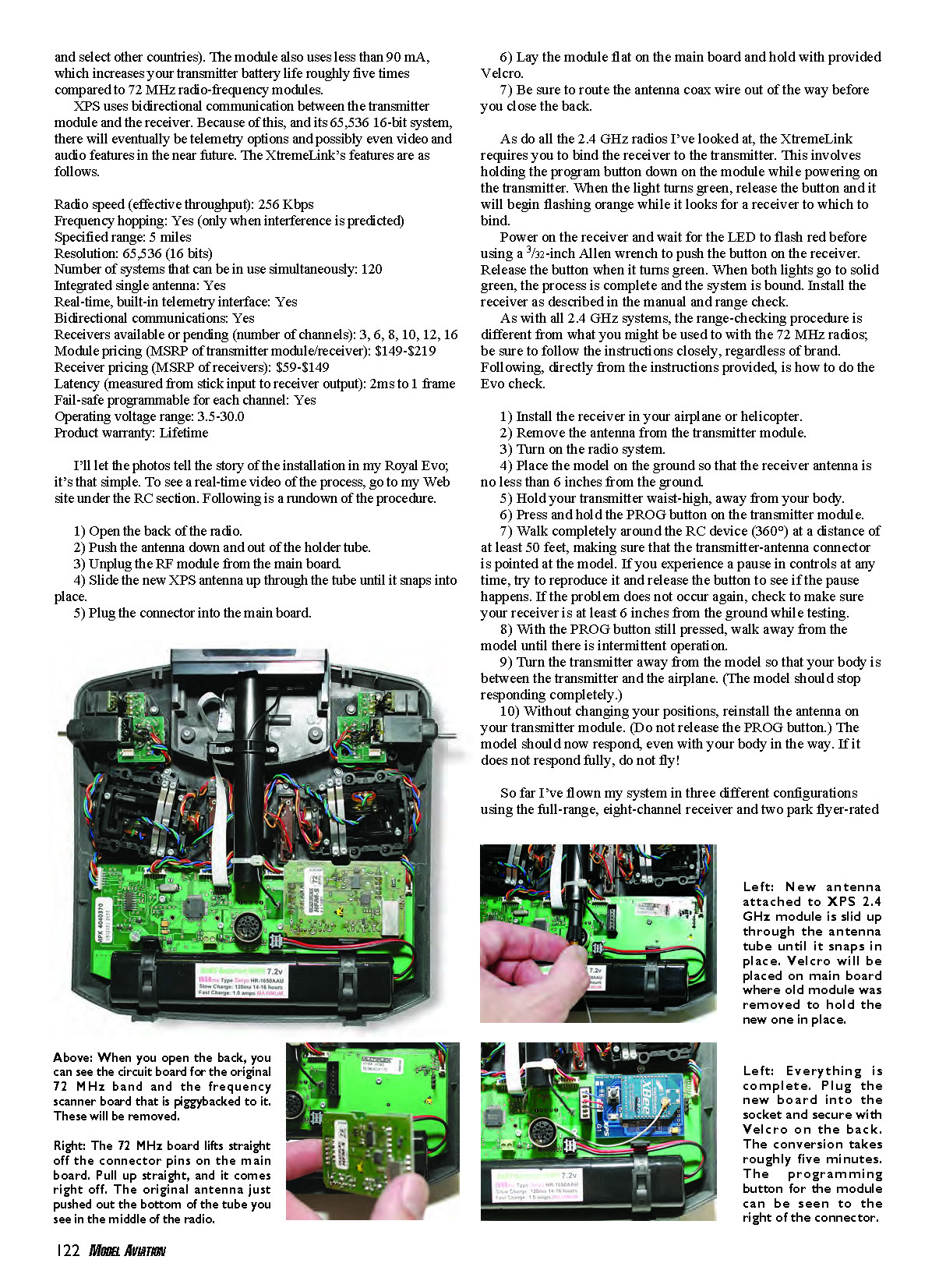
I'll let the photos tell the story of the installation in my Royal Evo; it's that simple. To see a real-time video of the process, go to my website under the RC section. Following is a rundown of the procedure.
- Open the back of the radio.
- Push the antenna down and out of the holder tube.
- Unplug the RF module from the main board.
- Slide the new XPS antenna up through the tube until it snaps into place.
- Plug the connector into the main board.
- Lay the module flat on the main board and hold it with the provided Velcro.
- Be sure to route the antenna coax wire out of the way before you close the back.
As with all the 2.4 GHz radios I've looked at, the XtremeLink requires you to bind the receiver to the transmitter. This involves holding the program button down on the module while powering on the transmitter. When the light turns green, release the button and it will begin flashing orange while it looks for a receiver to which to bind.
Power on the receiver and wait for the LED to flash red before using a 3/32-inch Allen wrench to push the button on the receiver. Release the button when it turns green. When both lights go to solid green, the process is complete and the system is bound. Install the receiver as described in the manual and range check.
As with all 2.4 GHz systems, the range-checking procedure is different from what you might be used to with the 72 MHz radios; be sure to follow the instructions closely, regardless of brand. Following, directly from the instructions provided, is how to do the Evo check.
- Install the receiver in your airplane or helicopter.
- Remove the antenna from the transmitter module.
- Turn on the radio system.
- Place the model on the ground so that the receiver antenna is no less than 6 inches from the ground.
- Hold your transmitter waist-high, away from your body.
- Press and hold the PROG button on the transmitter module.
- Walk completely around the RC device (360°) at a distance of at least 50 feet, making sure that the transmitter-antenna connector is pointed at the model. If you experience a pause in controls at any time, try to reproduce it and release the button to see if the pause happens. If the problem does not occur again, check to make sure your receiver is at least 6 inches from the ground while it is testing.
- With the PROG button still pressed, walk away from the model until there is intermittent operation.
- Turn the transmitter away from the model so that your body is between the transmitter and the airplane. (The model should stop responding completely.)
- Without changing your position, reinstall the antenna on your transmitter module. (Do not release the PROG button.) The model should now respond, even with your body in the way. If it does not respond fully, do not fly!
So far I've flown my system in three different configurations using the full-range, eight-channel receiver and two park-flyer-rated six-channel receivers, and I’ve had great performance.
The six-channel receiver installed in my aluminum-frame Corona helicopter is the worst-case scenario because it violates at least two criteria that XPS recommends, and so far it’s been flawless.
When installing these receivers, keep all wires secured away from the antenna. When wires are allowed to move around or contact the antenna, even getting close to it with movement might cause them to change tuning frequencies, thereby causing interference. This is a simple insurance measure that most of us ignore.
Final Approach
Some months the column space is too short, and this is one of those times. I could fill the whole issue with stuff I got from the Toledo show, and here I am on the way to the Southeast Electric Flight Festival and the Joe Nall fly-in in the next three weeks. Busy times and nothing but fun.
In the upcoming issues I’ll be looking at some great new things from TME for the Xtrema charger, along with the new RealFlight G4 simulator and its electric adaptability.
MA
Sources
- Approach Engineering — www.approachengineering.com
- Greg’s Toledo Show photos — www.gimlick.com
- Starwood Models — (650) 851-9027, www.starwoodmodels.com
- XPS — www.xtremepowersystems.net
Transcribed from original scans by AI. Minor OCR errors may remain.

