
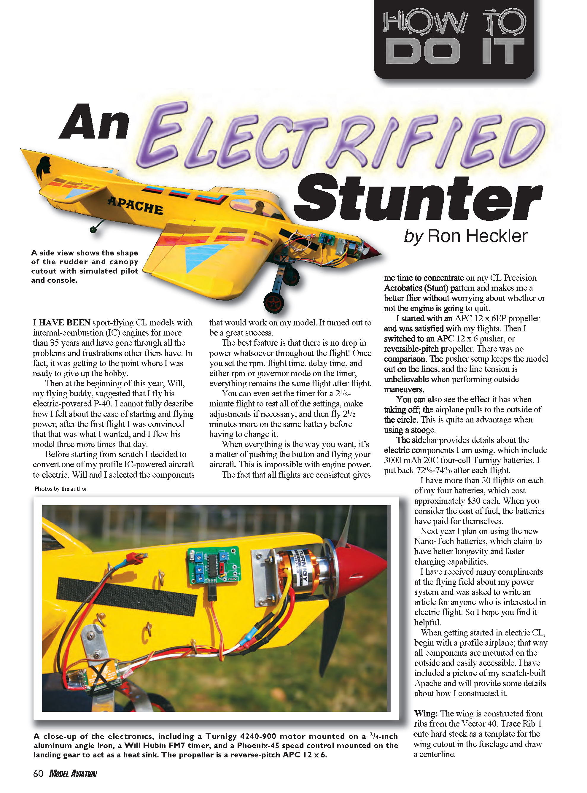
An Electrified Stunter
by Ron Heckler
I have been sport-flying CL models with internal-combustion (IC) engines for more than 35 years and have gone through all the problems and frustrations other fliers have. In fact, it was getting to the point where I was ready to give up the hobby.
Then at the beginning of this year, Will, my flying buddy, suggested that I fly his electric-powered P-40. I cannot fully describe how I felt about the ease of starting and flying with electric power; after the first flight I was convinced that that was what I wanted, and I flew his model three more times that day.
Before starting from scratch I decided to convert one of my profile IC-powered aircraft to electric. Will and I selected the components that would work on my model. It turned out to be a great success.
The best feature is that there is no drop in power whatsoever throughout the flight! Once you set the rpm, flight time, delay time, and either rpm or governor mode on the timer, everything remains the same flight after flight.
You can even set the timer for a 2 1/2-minute flight to test all of the settings, make adjustments if necessary, and then fly 2 1/2 minutes more on the same battery before having to change it.
When everything is the way you want, it’s a matter of pushing the button and flying your aircraft. This is impossible with engine power.
The fact that all flights are consistent gives me time to concentrate on my CL Precision Aerobatics (Stunt) pattern and makes me a better flier without worrying about whether or not the engine is going to quit.
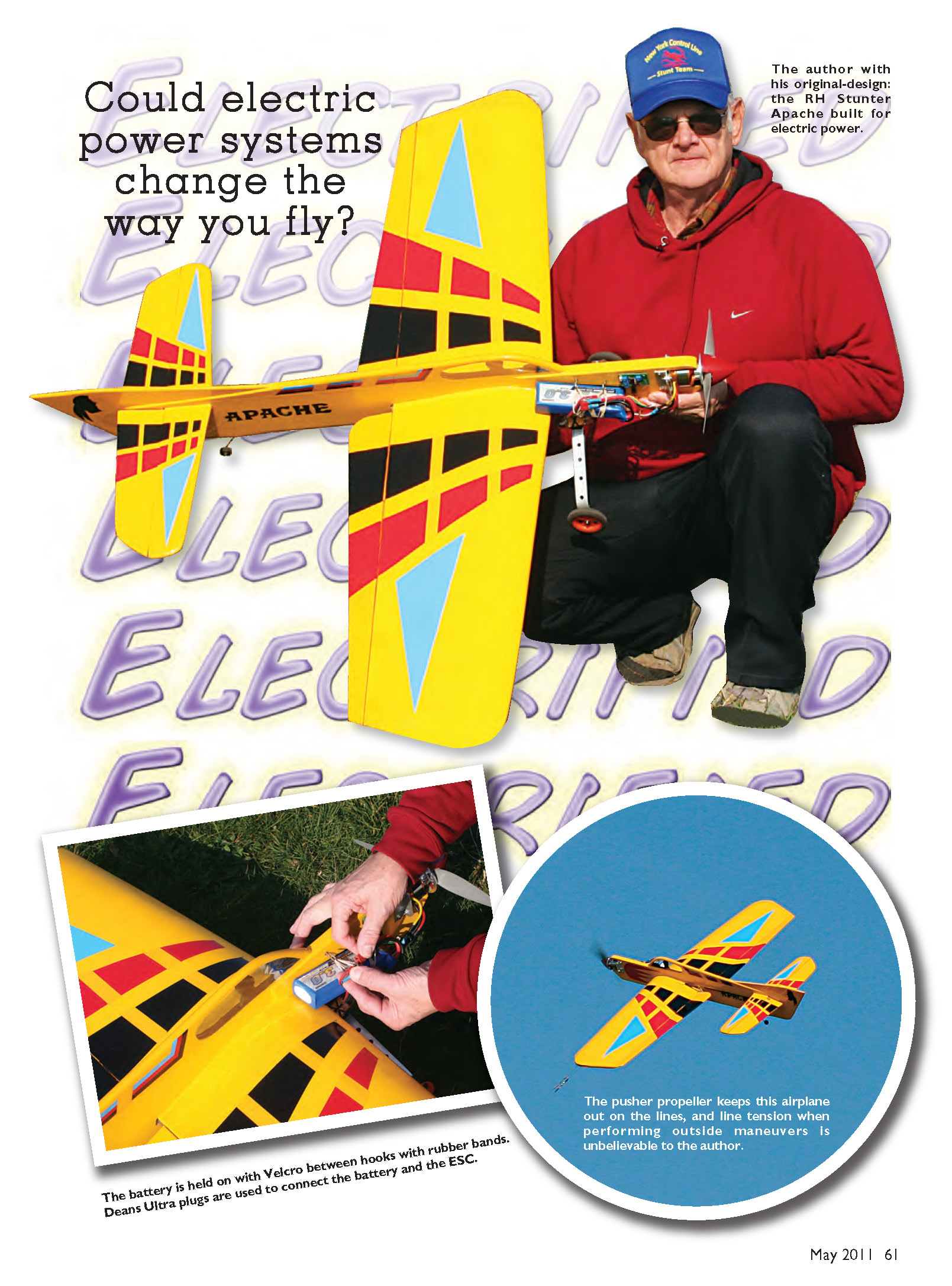
I started with an APC 12 x 6 EP propeller and was satisfied with my flights. Then I switched to an APC 12 x 6 pusher (reversible-pitch) propeller. There was no comparison. The pusher setup keeps the model out on the lines, and the line tension is unbelievable when performing outside maneuvers.
You can also see the effect it has when taking off; the airplane pulls to the outside of the circle. This is quite an advantage when using a stooge.
The sidebar provides details about the electric components I am using, which include 3000 mAh 20C four-cell Turnigy batteries. I recharge them to about 72%–74% after each flight.
I have more than 30 flights on each of my four batteries, which cost approximately $30 each. When you consider the cost of fuel, the batteries have paid for themselves.
Next year I plan on using the new Nano-Tech batteries, which claim to have better longevity and faster charging capabilities.
I have received many compliments at the flying field about my power system and was asked to write an article for anyone who is interested in electric flight. So I hope you find it helpful.
When getting started in electric CL, begin with a profile airplane; that way all components are mounted on the outside and easily accessible. I have included a picture of my scratch-built Apache and will provide some details about how I constructed it.
Wing
The wing is constructed from ribs from the Vector 40. Trace Rib 1 onto hard stock as a template for the wing cutout in the fuselage and draw a centerline.
The ribs are spaced so that the complete span, including wingtips, is 50 inches. I glued 16 pennies to the outboard tip, eight on the top and eight on the bottom, for tip weight; that equals 1 1/4 ounces. If desired, you can install an adjustable tip-weight box instead.
Excess balsa is removed from the ribs to reduce weight. The leadout wires are constructed from 7 inches of 1/32-inch-diameter music wire connected to the bellcrank, and the balance is flexible leadout cable. These are connected by using a piece of 3/32-inch-diameter copper tubing.
The 1/32 music wire and flexible cable are pushed through the tubing in opposite directions and then bent back over the tubing, wrapped, and soldered or epoxied. Doing this keeps the leadout wire from wearing through the bellcrank and eliminates the chance of the solid leadout wires being bent outside the wing.
Brodak Manufacturing sells laser-cut ribs for the Vector wing. If you decide to use a Vector foam wing, you can purchase one from Randy Smith or Bob Hunt.
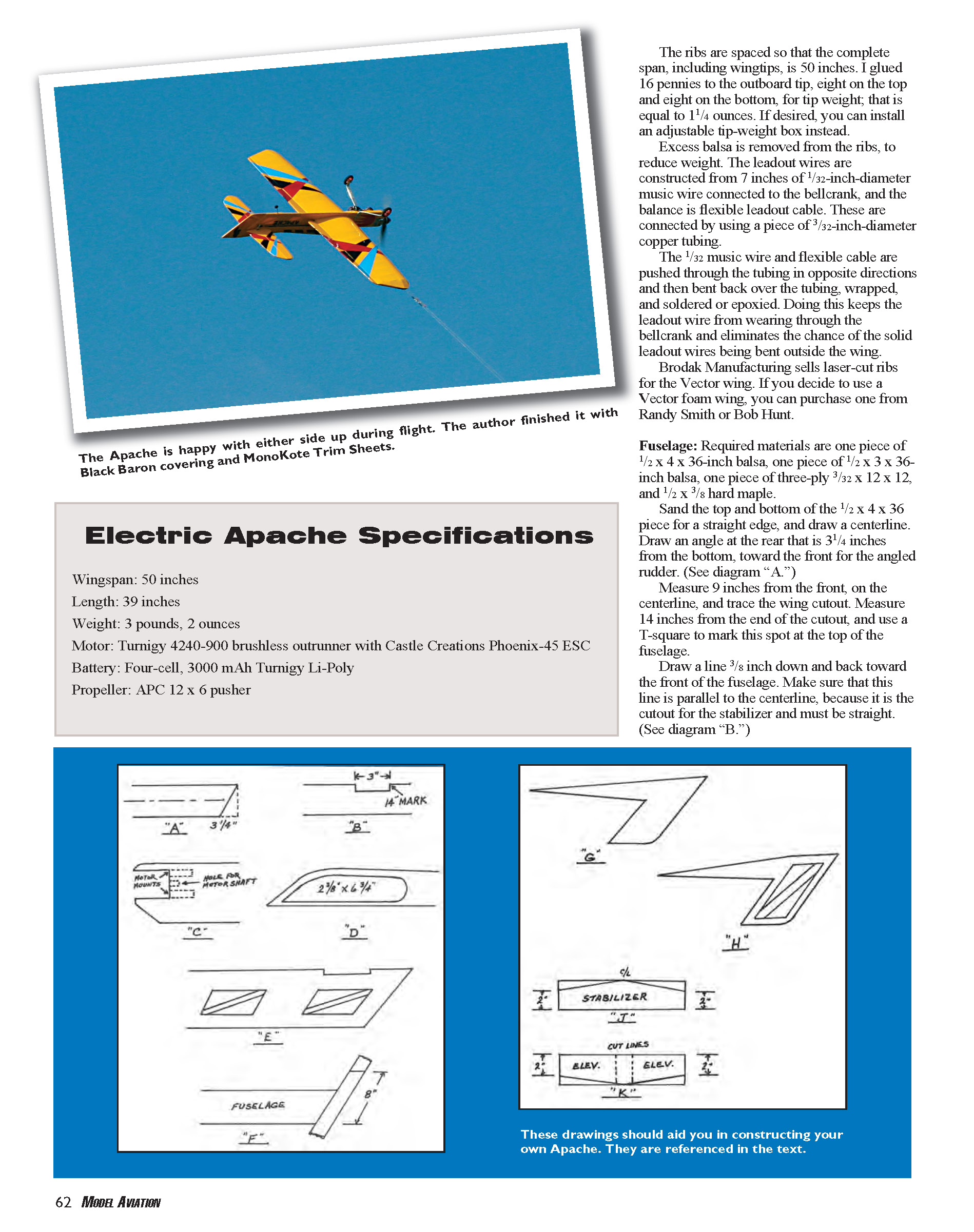
Electric Apache Specifications
- Wingspan: 50 inches
- Length: 39 inches
- Weight: 3 pounds, 2 ounces
- Motor: Turnigy 4240-900 brushless outrunner with Castle Creations Phoenix-45 ESC
- Battery: Four-cell, 3000 mAh Turnigy Li-Poly
- Propeller: APC 12 x 6 pusher
Fuselage
Required materials are one piece of 1/2 x 4 x 36-inch balsa, one piece of 1/2 x 3 x 36-inch balsa, one piece of three-ply 3/32 x 12 x 12, and 1/2 x 3/8 hard maple.
Sand the top and bottom of the 1/2 x 4 x 36 piece for a straight edge, and draw a centerline. Draw an angle at the rear that is 3 1/4 inches from the bottom, toward the front for the angled rudder. (See diagram "A".)
Measure 9 inches from the front on the centerline, and trace the wing cutout. Measure 14 inches from the end of the cutout, and use a T-square to mark this spot at the top of the fuselage. Draw a line 3/8 inch down and back toward the front of the fuselage. Make sure that this line is parallel to the centerline, because it is the cutout for the stabilizer and must be straight. (See diagram "B".)
Make a U-shaped motor cutout to allow clearance for the power plant you are using. I am using a Turnigy 4240-900 with a 2 1/4-inch spinner. I started 1/2 inch from the top, and the shape for this motor is 2 1/8 inches long and 2 inches wide. I made two 1 1/2-inch-long slots for the motor mounts at the top and bottom of the cutout.
Drill a hole in the center of the cutout to allow the shaft of the motor to turn freely. (See diagram "C" for correct locations.)
The piece of balsa between these two slots is left solid for the doublers. Glue the motor mounts in place and let dry. Draw an angle from the bottom of the spinner to the fuselage to simulate an air intake.
Trace the front of the fuselage on plywood doublers. Cut and sand the edges at an angle to blend with the fuselage around the wing area, and then glue in place.
Turtledeck
A 1/2 x 3 x 36-inch piece of balsa is required. Sand for a straight edge, and line it up with the top of the fuselage. Place it on top of the fuselage 8 inches from the front.
Tape those pieces together and draw the shape of the canopy 2 1/2 inches high maximum and down to 1/4 inch at the end of the fuselage. Cut at an angle to match the end of the fuselage.
Draw the inside dimensions of the canopy, which will be 6 3/4 inches long and 2 3/8 inches high maximum. When this is cut out, it will lighten the weight of the turtledeck. (See diagram "D".)
I decided to cover that area with clear MonoKote. A pilot could also be added.
Plane the rear of the fuselage and turtledeck to 1/4 inch to blend with the rudder. Cut lightening holes in the fuselage. (Shown in diagram "E.") Diagonals are left to support the covering. You can also cut a few holes in the turtledeck to lighten it.
Rudder and Fin
A piece of 1/4 x 3 x 36-inch balsa is required.
Lay the fuselage on its side. Place the balsa sheet at the rear, against the angle of the fuselage. (See diagram "F.") Leave a bit of extra at the bottom (approximately 1/2 inch) for final shaping and blending with the rear of the fuselage.
Tape the balsa piece to the fuselage and measure 8 inches up from the bottom. Using a straightedge, draw a line parallel to the top of the fuselage. Cut the 1/4 balsa at this line, and you have the rudder 3 x 8 1/2 inches.
Make the fin from the remaining sheet of 1/4 balsa. Place the fuselage on its side. Tape the turtledeck in place at the top, flush with the rear, and tape the rudder to the rear of the fuselage extending 1/2 inch, as before.
Make a light mark on the turtledeck 10 inches from the rear. This is where the fin will end and blend into the turtledeck.
Place the piece of 1/4 balsa lengthwise under the fuselage and rudder past the 10-inch mark. Draw a line from that mark tracing the turtledeck to the rudder to get the proper angle and contour.
Sketch a line straight down from the top of the rudder to the turtledeck and then from the top of the rudder to the 10-inch mark on the turtledeck. This makes the fin.
When you cut out the fin, make the angle from the 10-inch mark to the rudder by hand to match the contour of the turtledeck. You can cut the other lines with a straightedge.
Trial-fit and glue the pieces together with no offset. (See diagram "G".) When dry, draw a section for lightening holes. (Shown in diagram "H".) Cut out the areas at the top left and bottom right, leaving diagonals to support the covering.
Stabilizer and Elevators
A 3/8 x 3 x 36-inch and a 1/4 x 3 x 36-inch piece of balsa are needed for this section.
Draw the stabilizer as shown (see diagram "J") on the 3/8 balsa. It should be 22 inches long and 3 inches wide at the center, decreasing to 2 inches wide at each end.
Measure 1/4 inch on each side of the center and draw straight lines. This creates gluing area for the fuselage and centering.
Draw the elevators on the 1/4 balsa. They should be 22 inches long and 3 inches wide at the center, dropping to 2 inches wide at each end from the stabilizer. (See diagram "K".)
Measure 3/8 inch on both sides of center for fuselage clearance, and draw straight lines (cutting lines). Mark and drill joiner wire holes before cutting.
Tape to the stabilizer and shape the ends as desired. Then cut apart and add joiner wire.
Flaps
Two 1/4 x 3 x 36-inch pieces of balsa are required. Make full flaps 3 inches wide at the fuselage to 1 inch wide at the wingtips.
Landing Gear
This component is made from 1/8 x 3/4-inch aluminum stock, bent in a vise and drilled for lightness.
The preformed Sig Fazer landing gear or any profile landing gear that Brodak sells, such as that for the Cardinal, will work just as well, because it is bolted to the sides of the fuselage.
Finishing
The Apache's total flying weight (including an 11-ounce battery) is 50 ounces. When finishing your model, make it as light as possible. I like to use iron-on covering.
I covered the Apache with Black Baron material and MonoKote Trim Sheets (using the soapy-water method). Since no liquid fuel will be used, you can paint your model without using fuelproof paints. But be careful at the flying field to keep your airplane away from IC engine exhaust.
I am sure you will enjoy electric CL flying once you try it and see all of the advantages for yourself.
MA
Ron Heckler [email protected]
Sources:
- Brodak Manufacturing
- (724) 966-2726
- www.brodak.com
Transcribed from original scans by AI. Minor OCR errors may remain.

