

Electronics
Eloy Marez
2626 W. Northwood, Santa Ana CA 92704
THE INTERNET! We senior citizens have seen many wondrous changes in our lifetime in many things—close to us, of course, have been changes in full-scale and model aviation.
But for the world's population in general, with the possible exception of television, I doubt if anything has had as great an effect as the personal computer—specifically the Internet and what it has brought us.
However, as do many other things, it has its questionable values. To many, "I got it on the Internet" seems to have the same value as "Moses brought it down from the mount carved on a tablet of stone." It is completely believable—gospel.
That is not so, my friends!
Not that I claim to be knowledgeable about or experienced with all subjects to be found on the 'net, but when it comes to the one at hand I am often appalled at the misinformation being passed around amongst Radio Control (RC) 'net surfers.
Not that I am one of the above mentioned, but I do browse around now and then to get an idea of what people are interested in.
It appears that often, in answer to someone's question, others feel compelled to answer and offer advice—even if they have to start with "I think" or "I heard," and not with any actual basis.
One such item I saw in one of the forums read, "Does dual conversion necessarily mean 1024 or is it possible to have a Futaba receiver with dual conversion and a resolution of 512? For example, is a Futaba FFR-128-DP dual-conversion PCM also a 1024?"
The answer from one helpful person was:
"I believe [key phrase] dual conversion refers to how the received signal is translated in the Rx [receiver]. Single conversion mixes the received rf [radio frequency] signal with a known signal within the Rx to get the intelligence (your input) out of the rf signal. This mixing is done once in a single-conversion Rx; dual conversion mixes twice to demodulate the received signal.
"By the way, this has nothing to do with PCM. PCM means Pulse Code Modulation. It is a form of modulation—not conversion."
At least this person starts off with "I believe," and not with "I, Moses, having just come off the hill ..."
But then he goes off into a 110% incorrect treatise about something he obviously knows little about. Why he chose to do so is for someone with experience other than mine to explain, but is an example of the sort of "help" one finds on the 'net.
In a single-conversion receiver, the incoming signal is indeed mixed once with the crystal frequency and "converted" to 455 kilohertz (kHz), at which frequency all of its processing takes place.
The "intelligence" referred to is not "decoded" or "demodulated" as mentioned until two more stages—detector and audio—and is done not at the front mixing stage, but at another circuit called a "decoder."
It "decodes" the information input into the transmitter by an "encoder"—makes sense, no?
The phantom writer is partly correct in his description of PCM, which is, in spite of the word "modulation" being part of its name, a form of encoding.
The description obviously comes from its original application in electronic devices outside of RC. It can also be described as "computer-speak."
In advertising jargon, PCM devices have become "digital," such as digital television, etc. Actually, your telephones—cellular and cordless—digital video, many audio systems, and, by now, probably your dishwasher and vacuum cleaner use PCM control in some form.
And more to the point, the advice in one of the quoted letters on how to reverse the rotation of a servo was, "just reverse the red and black wires at the plug."
If you do, don't lean over it when you test it; the smoke can be really irritating.
Beware the Internet! But then, that is good advice about many things, isn't it?
Lightweight jack switch
More well-intentioned good advice! In the February '91 issue, there was an article "Make a Lightweight Switch"—a replacement for the normal airborne equipment switch—by Mr. Robert Boyce.
It is a very well-done article, with clear descriptions, diagrams, and a parts list—everything the uninitiated needs to duplicate the device.
As my New Zealander friends would say, "Good on you, Bob!"
The article starts with the statement, "This jack switch is ideal for a small sailplane or park flier."
That's a very important sentence, and I will come back to it. But first, a short description!
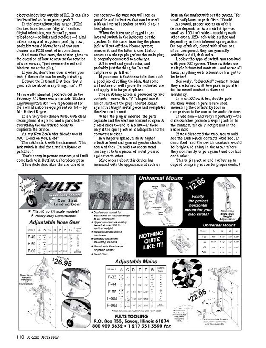
The article describes the use of audio connectors—the type you will see on portable audio devices that can be used with an internal speaker or with plug-in headphones.
When the latter are plugged in, an internal switch in the jack cuts out the speaker. In this case, inserting the phone jack will cut off the airborne system; remove it, and the latter is on. It also serves as a choke plug when the male plug is properly connected to a charger.
All is well and good so far, and probably just the thing for "a small sailplane or park flier."
My concern is that the article does such a good job of selling the idea, that some will not see or will ignore the indicated use and apply it to larger airframes.
The switching action is provided by two contacts—one with a "V" shaped into it, which, without the plug inserted, bears against a straight metal piece and completes the electrical circuit.
When the plug is inserted, the parts separate and the electrical circuit is open. A closed circuit—and reliability—is there only if the spring action is adequate and the contacts are clean.
In a larger airframe, with its higher vibration level and greater shocks now and then, I would not recommend trusting it to two pieces of metal pressed against each other.
My concern about this device has increased with the appearance of such an item on the market without the caveat, "for small sailplanes or park fliers." Ouch!
As stated, proper operation of this device depends on two metal strips—as small as 0.100 inch wide—touching each other over a 0.050 inch-wide surface and depending on their inherent spring. On top of which, plated with silver or silver compound, they are generally a grayish, dull, dark color.
Look at the type of switch you received with your RC system. These switches use multiple bifurcated contacts—and as we all know, anything with bifurcation has only to be better!
Seriously, "bifurcated" contacts means they are forked, with two parts in parallel for increased contact surface and reliability.
In most RC switches, double-pole switches wired in parallel are used, increasing the contacts by four in comparison to the one in the audio devices.
In addition—and very importantly—the slide switches provide a wiping action to the contacts, which is not present in the audio jack.
If you dissected the two, you would see the audio jack contacts oxidized, as described, and the switch contacts would be bright and shiny in the areas where they constantly wipe against and contact each other.
This wiping action, and not having to depend on spring action for proper contact, is the same reason why toggle switches are not common for RC airborne use.
Though generally cheaper, a good-quality slide switch is the king here.
Batteries and fail-safe
Batteries are the subject of many questions that come my way, including some that must sound ridiculous to many of you experienced R/Cers.
But do you remember your beginning days and how confusing all this stuff was?
One question I was asked at the field recently was, "Will the receiver battery fail-safe in my — ? I work normally if I use a five-cell battery?"
Most of us know it won't. The circuit is set to actuate whenever the four-cell battery voltage is at a critical level—probably near 4.4 volts—depending on the radio designer.
Under normal use, even when almost completely discharged, the five-cell battery voltage will never get that low. If it does, you will have another type of warning called "I ain't got it!"
But it is still a good question; it is not an original thought, but there is a great deal of truth to the statement that "the only dumb questions are the ones that don't get asked."
Circuit of the month: Polarity tester
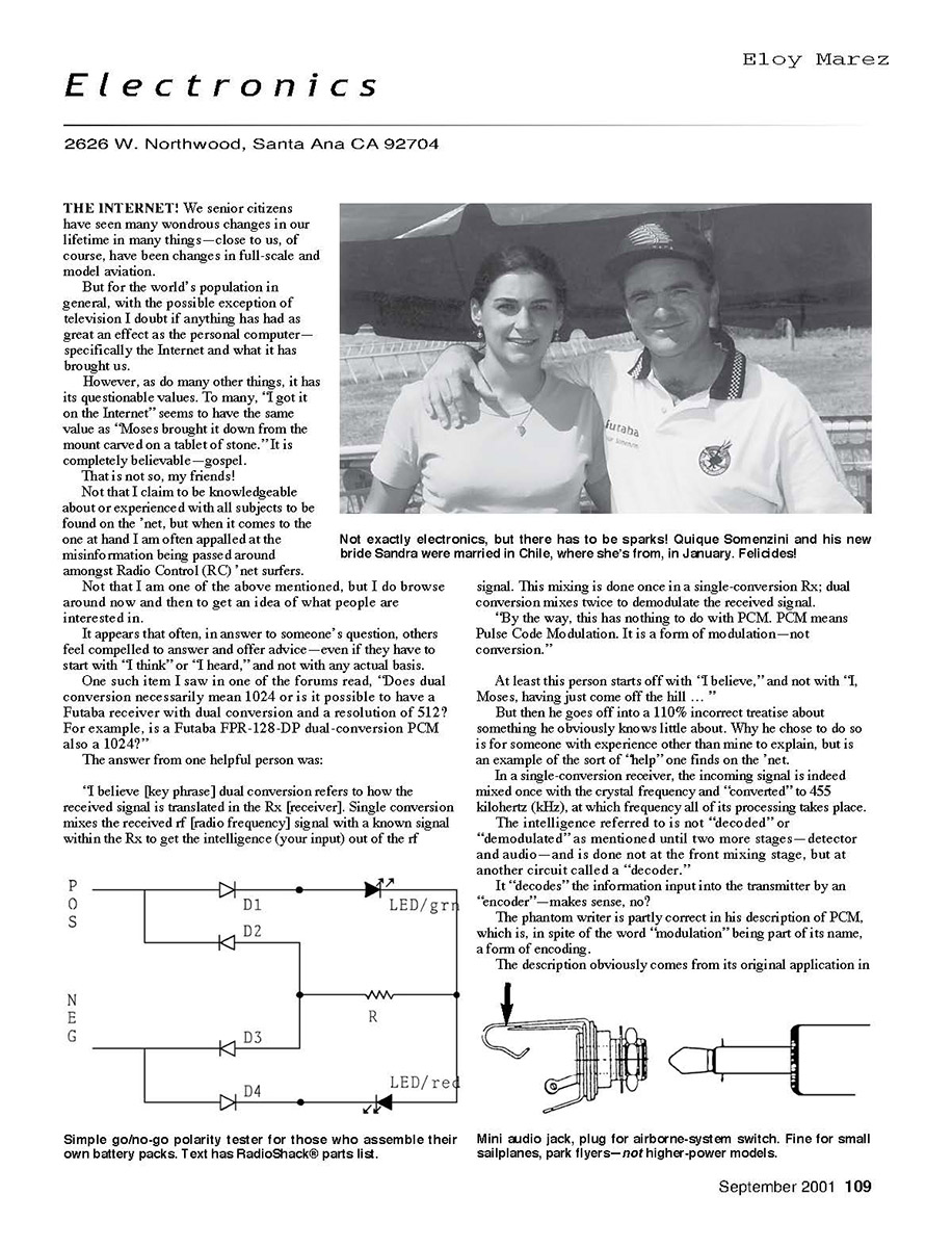
As repeat readers know, I don't include a circuit each month, so that is not a correct heading. However, I have one for you this month: a polarity tester for those of you who like to assemble your own battery packs.
It is a rather simple but effective polarity tester. When plugged into a battery, it will give you a green-light (light-emitting diode [LED]) indication if it is "go" and a red light if it is a "no go."
However—and this is very important—you have to be 100% sure that the connections to the tester are initially correct; reverse connections will give you a reversed, erroneous indication.
The only completely foolproof way I can think of around that possibility is to equip your tester with a polarized connector that mates with whatever battery connectors you use.
You only need to be correct during its assembly; from then on, there is no possibility of an incorrect connection.
Refer to the schematic. As stated, the tester is simple—although the polarity of the components has to be observed throughout.
On D1 and D2, the LEDs' cathode, the side designated by the flat mark is indicated on it by the shorter of the two leads. Also, looking at the base of the LED, the cathode lead will have a flat spot adjacent to it.
The RadioShack® parts listed later come on a card with this information printed on the back.
On D1 through D4—the power diodes—the cathode, the flat mark, is indicated on its body by a black band. The resistor R1 is not polarized, and can be installed in any manner.
For voltages as high as 12 volts, use the 1K (1,000) ohm resistor indicated. For higher voltages, to keep the LED current down to a safe limit, increase it to 1.5K.
As mentioned, the polarity of the diodes and the LEDs, and the input connections, is critical. There is nothing critical about the parts placement or anything else.
Assemble the few pieces on a section of the perforated component board listed. If you really want to do it professionally, mount it in one of the many small plastic enclosures available from RadioShack®; the one listed is just a recommendation.
Parts list:
- D1–D4 RS 276-022
- D1–D4 RS 276-041
- D1–D4 RS 276-1101
- R1–1K RS 271-1118
- R1–1.5K RS 271-1120
- Board RS 276-150
- Case RS 270-1801
Testing for correct battery pack polarity, whatever method you choose to use, is important. Reverse voltage will generally cause damage to whatever it is applied to.
Transcribed from original scans by AI. Minor OCR errors may remain.

