

Electronics
2626 W. Northwood, Santa Ana CA 92704
SERVOS: With the exception of batteries and chargers, I get more mail and queries about servos than about any other part of the Radio Control (RC) system. One of the recent letters came from Glen G. House of Bath, New York, who writes:
"Recently, I purchased some Futaba S-148 servos. Upon reading the instructions (yeah, I even read them once in a while!) I find that they state, and I quote: 'Futaba servos can not be used with other makes of RC sets.' They also state that they are a positive pulse.
"The instructions that came with my Ace Olympic V radio set state that I can use any brand of servo as long as they are positive pulse. What gives? Is there any reason why I can't use my 148s with my Ace? The receiver is a model 91 narrow band and I am presently using some old Royal Titan II standard servos. They are getting a little tired."
The answer is a definite "maybe"! Regardless of the type of RC system in use, AM or FM (Pulse Code Modulation [PCM] transmission is done on FM, and Pulse Position Modulation [PPM] is a misnomer for FM), the servo bottom line — the control signal — is Pulse Width Modulation (PWM). That is, the position of the servo output, at center or at any position in either direction, is determined by the length of the control signal.
This length is generally expressed in time, in milliseconds (ms—thousandths of a second), though sometimes, when greater accuracy is intended, it is expressed in microseconds (µs—millionths of a second). Fortunately, a standard for all makes of servos is now in use: 1.5 ms for neutral, plus or minus (1.0-2.0 ms) for extremes of travel in both directions.
This control pulse is a Direct Current (DC) voltage, but bear in mind that it is not its amplitude—its voltage rating—that controls the servo, but its length.
The servo is fed this signal from the receiver, though it is generated by the transmitter at nominally a 50-times-per-second rate; i.e., at 50 hertz. The non-PCM receiver does not originate this signal and, with the exception of the fail-safe-equipped PCM type, does not have the ability to do so.
Such a receiver, with the aid of a computer microprocessor, can be programmed via the transmitter to originate servo-control pulses when control information from the transmitter is lost or interfered with. Again, your normal AM or FM receiver does not actually control your servos; think of it as a piece of wire that is carrying original control information from the control sticks to the servos.
This 50-times-per-second input pulse ultimately triggers power pulses to the servo motor, at the same rate. The servo motor does not receive constant battery voltage whenever it is running; it is powered in short bursts, fast enough not to be noticeable but still not constant.
Here is where we run into the major difference between the common servos and the new (digital) designs. In the latter, again with the aid of microprocessor control, the motor pulses are applied at a much higher rate; the motor receives voltage a higher percentage of the time and is thus able to operate at a higher speed and develop more power.
The (the) reference to digital servos is because although we are now being subjected to all the advertising of these "new" servos, the German Multiplex company was producing them some 20 years ago—programmable as to direction, speed, throw, etc. There are new things in RC, but digital servos is not one of them!
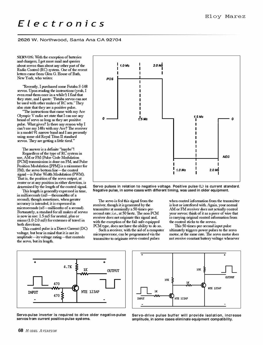
Have patience, Glen; we've arrived at the positive-signal business! As stated, the servo-control pulse is a DC voltage, which, starting from a nominal zero point, can be positive or negative. Please refer to the sketch.
Currently all servos made are operated by a positive-voltage control pulse, although either could be used with proper servo design. In the early days of proportional multichannel radio control, some manufacturers—slightly less than half of the 20 or so that have appeared through the years—chose to go with a negative signal for reasons not now known, but the remaining ultimately settled on a positive pulse.
What happened to all these servos?
Apparently there are none such around that I get requests for how to modify them for positive system use. I have included the required pulse inversion circuit required which in some cases, since most of the earlier servos were comparatively large, can be put right inside.
This is not a servo receiver, which is another thing entirely. I would not recommend such servos for use in your best Szel Master's quality airplane, but they should be acceptable for both trainer and auxiliary uses.
What about modern servo interchangeability, such as Gen's S-1A86? They are all positive pulse, designed for 10-20 mS timing and, with the exception of different plugs and in some cases wire color and sequence, are almost 100% interchangeable. The percentage is higher than "almost 100%" for the lower end—the so-called standard servos. More inconsistencies seem to crop up with the higher performance competition types.
I have received word of different equipment incompatibility, but there are too many possible combinations to form any kind of conclusion. Quite possibly, there is one consideration. As stated, the servo control pulse has a definite amplitude—a certain amount of voltage. Servos from the same manufacturer are designed to operate optimally with that particular pulse amplitude.
I do not have any hard model Futaba receivers on hand and do not know if there have been design changes, but those of a few years ago produced a pulse of lower amplitude than similar receivers. Futaba servos worked perfectly with them, but this weaker pulse could result in improper operation when such receivers are used with other brands of servos which are primarily designed for use with their own brand of receivers—those with a higher pulse amplitude.
The difference in pulse amplitude is small—tens of a volt. But in solid-state electronics such as RC equipment, low voltages are common and small amounts can be high when percentages are considered. I have had reports of servo nervousness when using Futaba receivers and JR digital and Airtronics 357 and 358 servos.
There may be, and probably are, other factors involved, but there is not enough data to know what combination will and will not work normally. In some cases a buffer amplifier, inserted between the receiver and the servo, will cure the problem. Such buffers are available commercially, such as the Glitch Buster from EMS (Electronic Model Systems).
For those of you who like to roll your own, I have included a relatively simple circuit that provides some isolation and beefs up the PWM signal slightly.
Consider keeping your receiver/servo combinations all of the same brand, even though I know that for many reasons it is not always possible. Mix-and-match combinations come with a built-in problem: if you experience less-than-optimum operation, it is difficult to separate from either of the two companies involved.
The receiver maker will tell you that its product is operating normally, as will the servo manufacturer (and, important), yet neither will service or even test them together. This is a criticism of any RC company: none of them can be expected to stock parts, or to have technicians trained on equipment of their mixing.
Independent service centers do exist, and most will probably tackle a mixed-bag problem and may even have previously experienced and solved the one that is troubling your equipment.
The service centers I know of are DEM Electronics (1226 Marigold St NW, Hartville OH 44632 Tel.: [330] 877-1146; E-mail: [email protected]; Website: www.dmelectronics.com), KDI (7420 Seven Mile Rd., Northville MI 48167; Tel.: [248] 486-4800; Fax [248] 486-1008; E-mail: [email protected]), and Radio Suomi (3727 NE Pave Blvd., Pensacola FL 32505 Tel.: [850] 454-0099; Website: www.radiosuomi.com). Last but not least is the matter of plug compatibility. The matter of different battery polarity disappeared a couple years ago with the introduction of the Airtronics Z-connector, although removal of the plug still requires a special plug to be removed before the plug can be inserted into receivers of other brands.
Many different adapters to mate one brand of servo to different receivers are available, but I don't recommend them; they add one more failure point per servo to the wiring system, and who needs more problems?
It's far better to replace the servo plug ends with the correct service connector. Or if you are of the field-repair type, you can purchase the proper pliers, metal inserts, and crimping tool from Peak Electronics (12530 Kirkham Ct. #6, Poway CA 92064 Tel.: [858] 679-4922; Website: www.peak-electronics.com), which now markets the wire-inserts and crimping tool built from Custom Electronics.
I have heard the advice given that one should solder the wires into the connectors. Wrong! To do so requires heat, and heat will, over the temperature from the very thin metal they are formed from, resulting in reduced contact pressure and intermittent contact.
If you must solder them, use a heatsink between the business end of the connector and the solder joint. A locking-type forceps will do the job.
So, then, establish a range check with your original servos. Plug in your new replacements, make a comparison check, and unless you see a lot of range, goofy! And all of you, let me know what success—or lack of same—you have with solving compatibility problems with different brands; it might help someone else somewhere. WA
Transcribed from original scans by AI. Minor OCR errors may remain.

