
Electronics
Eloy Marez
Fortunately for us radio-control fliers, because of the tremendous demand for rechargeable batteries brought about by the equally tremendous use of battery-powered devices such as cell phones, broadcast receivers, compact-disc and tape players, laptop computers, etc., we now have batteries that are greatly improved compared to those of even a few years ago.
Of course, rechargeable batteries are no better than the equipment used to revitalize them. Although the battery chargers that come with today's radio systems do the job, there are more modern and more efficient chargers on the market. There are so many more modern chargers that, coupled with the latest battery chemistries, the proper choice of a battery charger can be confusing. But that is another story.
However, since many of these chargers are intended for field use and must be powered by 12-volt batteries, a separate AC (wall-socket) power supply must be used to provide the 12 volts required. Such power supplies are available within the hobby market and through general electronics suppliers, but those with the necessary high-current capability are somewhat costly—especially for those who have only occasional use for such an item.
That was the bad news, and here is the good news. Actually, it couldn't be "gooder." There is a 12-volt-plus power supply that in many cases will cost you nothing other than a few minutes of work with your soldering iron. We are going to convert a common computer power supply into a voltage source for your DC-powered charger.
Don't panic; this will require no real electronics experience—merely the need to follow instructions. And with the proper choice of one component—a resistor—you have some control over the exact output voltage. Most DC-powered chargers will accept, and some even like, a voltage slightly higher than 12 volts. My adaptation, which I will describe, is set for 13.20 volts, which is a recommended value.
ATX power supplies
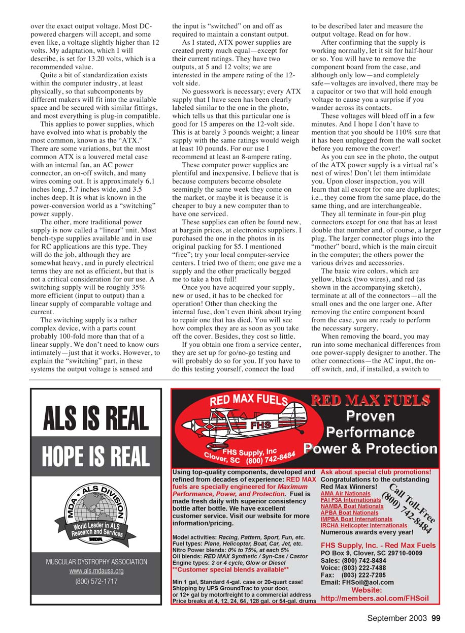
Quite a bit of standardization exists within the computer industry, at least physically, so that subcomponents by different makers will fit into the available space and be secured with similar fittings, and most everything is plug-in compatible. This applies to power supplies, which have evolved into what is probably the most common, known as the "ATX." There are some variations, but the most common ATX is a louvered metal case with an internal fan, an AC power connector, an on-off switch, and many wires coming out. It is approximately 6.1 inches long, 5.7 inches wide, and 3.5 inches deep.
It is what is known in the power-conversion world as a "switching" power supply. The other, more traditional power supply is now called a "linear" unit. Most bench-type supplies available and in use for RC applications are this type. They will do the job, although they are somewhat heavy, and in purely electrical terms they are not as efficient, but that is not a critical consideration for our use. A switching supply will be roughly 35% more efficient (input to output) than a linear supply of comparable voltage and current. The switching supply is a rather complex device, with a parts count probably 100-fold more than that of a linear supply. We don't need to know ours intimately—just that it works. However, to explain the "switching" part, in these systems the input is "switched" on and off as required to maintain a constant output.
As I stated, ATX power supplies are created pretty much equal—except for their current ratings. They have two outputs, at 5 and 12 volts; we are interested in the ampere rating of the 12-volt side.
No guesswork is necessary; every ATX supply that I have seen has been clearly labeled similar to the one in the photo, which tells us that this particular one is good for 15 amperes on the 12-volt side. This is at barely 3 pounds weight; a linear supply with the same rating would weigh at least 10 pounds. For our use I recommend at least an 8-ampere rating.
These computer power supplies are plentiful and inexpensive. I believe that is because computers become obsolete seemingly the same week they come on the market, or maybe it is because it is cheaper to buy a new computer than to have one serviced.
These supplies can often be found new, at bargain prices, at electronics suppliers. I purchased the one in the photo in its original packing for $5. I mentioned "free;" try your local computer-service centers. I tried two of them; one gave me a supply and the other practically begged me to take a box full!
Checking and preparing the supply
Once you have acquired your supply, new or used, it has to be checked for operation. Other than checking the internal fuse, don't even think about trying to repair one that has died. You will see how complex they are as soon as you take off the cover. Besides, they cost so little.
If you obtain one from a service center, they are set up for go/no-go testing and will probably do so for you. If you have to do this testing yourself, connect the load to be described later and measure the output voltage.
After confirming that the supply is working normally, let it sit for a half-hour or so. You will have to remove the component board from the case, and although only low—and completely safe—voltages are involved, there may be a capacitor or two that will hold enough voltage to cause you a surprise if you wander across its contacts. These voltages will bleed off in a few minutes. And I hope I don't have to mention that you should be 110% sure that it has been unplugged from the wall socket before you remove the cover!
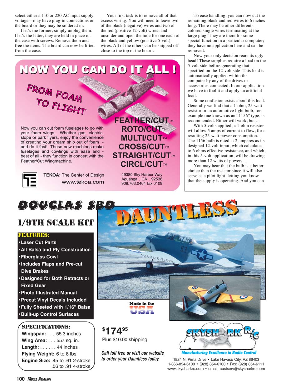
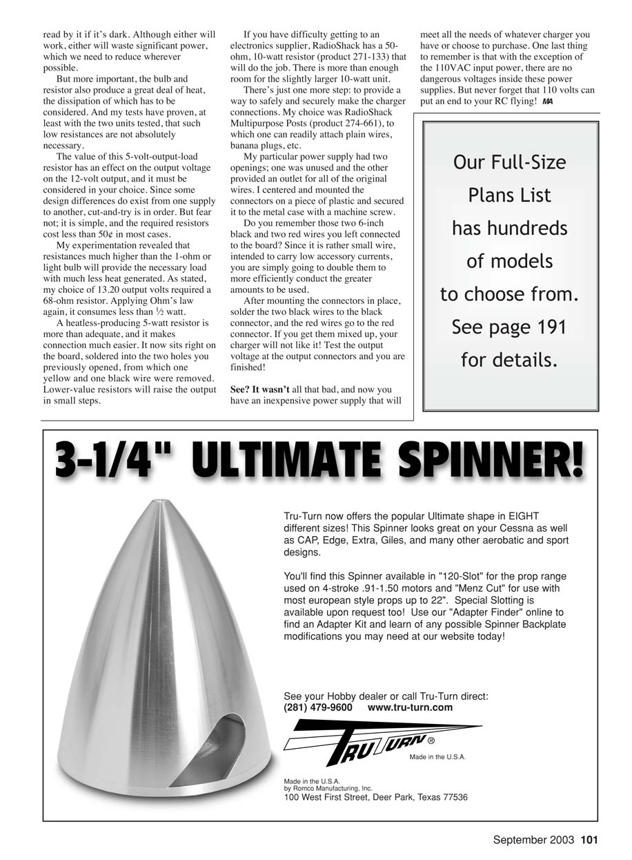
As you can see in the photo, the output of the ATX power supply is a virtual rat's nest of wires! Don't let them intimidate you. Upon closer inspection, you will learn that all except for one are duplicates; i.e., they come from the same place, the same thing, and are interchangeable.
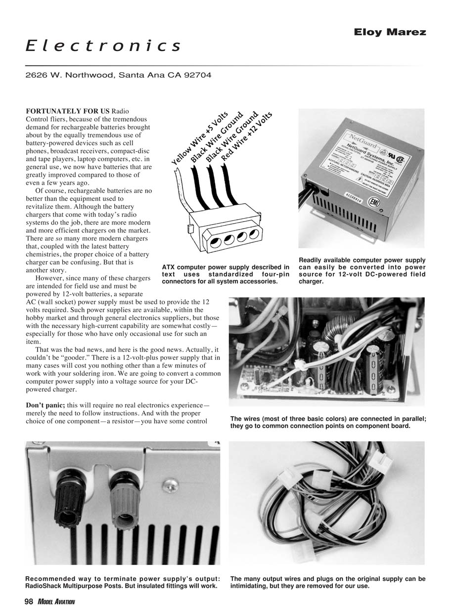
They all terminate in four-pin plug connectors except for one that has at least double that number and, of course, a larger plug. The larger connector plugs into the "mother" board, which is the main circuit in the computer; the others power the various drives and accessories.
The basic wire colors—yellow, black (two wires), and red—terminate at all of the connectors—all the small ones and the one larger one. After removing the entire component board from the case, you are ready to perform the necessary surgery.
When removing the board, you may run into some mechanical differences from one power-supply designer to another. The other connections—the AC input, the on-off switch, and, if installed, a switch to change operational voltages from 115 to 230 volts—are usually where the power cord is attached. If such a switch is present, set it for 117 volts (or 120 V as appropriate) before connecting to the wall socket. Next, remove the screws that hold the board in place and lift it out.
Select either a 110 or 220 AC input supply voltage—these may have plug-in connections on the board or they may be soldered in.
- If it's the former, simply unplug them.
- If it's the latter, they are held in place on the case with screws. Remove them and free the items.
The board can now be lifted from the case.
Wire trimming and keeping required leads
Your first task is to remove all of that excess wiring. You will need to leave two of the black (negative) wires and two of the red (positive 12-volt) wires, and unsolder and open the hole for one each of the black and yellow (positive 5-volt) wires. All of the others can be snipped off close to the top of the board.
To ease handling, you can now cut the remaining black and red wires to 6 inches long. There may be other differently colored single wires terminating at the large plug. They are there for some special function in a particular computer; they have no application here and can be removed.
Applying the 5-volt load
Now your only decision rears its ugly head! These supplies require a load on the 5-volt side before generating that specified on the 12-volt side. This load is automatically applied within the computer by any of the drives or accessories connected. In our application we have to fool it and apply an artificial load.
Some confusion exists about this load. Generally we find that a 1-ohm, 25-watt resistor or an automotive light bulb—for example one known as an "1156" type—is recommended. Either will work, but consider the implications.
With 5 volts applied, a 1-ohm resistor will allow 5 amps of current to flow, for a resulting 25-watt power consumption. The 1156 bulb is rated at about 2 amperes at its designed 12-volt input, which calculates to about 6 ohms effective resistance, and which, in this 5-volt application, will be drawing more than 12 watts of power.
You may hear that the bulb is a better choice than the resistor since it will also serve as a pilot light, letting you know that the supply is operating. And you can read by it if it’s dark. Although either will work, either will waste significant power, which we need to reduce wherever possible.
But more important, the bulb and resistor also produce a great deal of heat, the dissipation of which has to be considered. And my tests have proven, at least with the two units tested, that such low resistances are not absolutely necessary.
The value of this 5-volt-output-load resistor has an effect on the output voltage on the 12-volt side, and it must be considered in your choice. Since some design differences do exist from one supply to another, cut-and-try is in order. But fear not; it is simple, and the required resistors cost less than 50¢ in most cases.
My experimentation revealed that resistances much higher than the 1-ohm or light bulb will provide the necessary load with much less heat generated. As stated, my choice of a 13.20-volt output required a 68-ohm resistor. Applying Ohm’s law again, it consumes less than 1/2 watt.
A low-heat 5-watt resistor is more than adequate, and it makes connection much easier. It now sits right on the board, soldered into the two holes you previously opened, from which one yellow and one black wire were removed. Lower-value resistors will raise the output in small steps.
If you have difficulty getting to an electronics supplier, RadioShack has a 50-ohm, 10-watt resistor (product 271-133) that will do the job. There is more than enough room for the slightly larger 10-watt unit.
Final assembly and output connectors
There’s just one more step: to provide a way to safely and securely make the charger connections. My choice was RadioShack Multipurpose Posts (product 274-661), to which one can readily attach plain wires, banana plugs, etc.
My particular power supply had two openings; one was unused and the other provided an outlet for all of the original wires. I centered and mounted the connectors on a piece of plastic and secured it to the metal case with a machine screw.
Do you remember those two 6-inch black and two red wires you left connected to the board? Since it is rather small wire, intended to carry low accessory currents, you are simply going to double them to more efficiently conduct the greater amounts to be used.
After mounting the connectors in place, solder the two black wires to the black connector, and the red wires go to the red connector. If you get them mixed up, your charger will not like it! Test the output voltage at the output connectors and you are finished!
See? It wasn’t all that bad, and now you have an inexpensive power supply that will meet all the needs of whatever charger you have or choose to purchase.
Safety reminder
One last thing to remember is that with the exception of the 110 VAC input power, there are no dangerous voltages inside these power supplies. But never forget that 110 volts can put an end to your RC flying!
MA
Transcribed from original scans by AI. Minor OCR errors may remain.

