
TRAINER SYSTEMS
Eloy Marez
Basics of Buddy Boxes
Trainer systems are more commonly referred to as "buddy boxes." I could not locate a definitive reference, but I remember reading somewhere that the German Multiplex company was the first—or claimed to be the first—to introduce them.
That would not surprise me; Multiplex has been a leader in Radio Control (RC) technology for years. For instance, the big names in RC are running the race in digital servos years after the fact; Multiplex had digital servos at least 10 years ago!
In this country there is no doubt who was the "fustest with the mostest"; it was Bob Dunham's Orbit Electronics, which pioneered much of the equipment we enjoy today and was advertising "The End of the Crash Course" sometime in the 1960s. Kraft Systems, EK Logictrol, and ProLine—the big ones of that era (now unfortunately all gone)—soon followed.
We have beginners with us, so you experienced readers please bear with me! The RC trainer system is a dual-control method of teaching RC flight during which the experienced instructor pilot makes the takeoff and trims the airplane. Then, with the actuation of a switch, the fledgling pilot takes control.
If the newcomer gets the model into an unrecoverable attitude at any time, the instructor releases the switch, regains control, and recovers the airplane. The instructor's transmitter is referred to as the "master"; the transmitter the trainee uses is called the "slave," or "trainer."
This is not a universally accepted method of teaching RC flying. Some instructors prefer to hand the transmitter to the student, and they expect that he or she will admit to being confused and graciously relinquish the transmitter when asked to do so. I have seen some wrestling matches take place at such times, and I have successfully used the buddy-box training technique many times, but as with everything else in RC, there is more than one way to train. Teaching another person is a unique skill; not all good RC fliers make good instructors with or without a buddy box.
Transmitter Sections
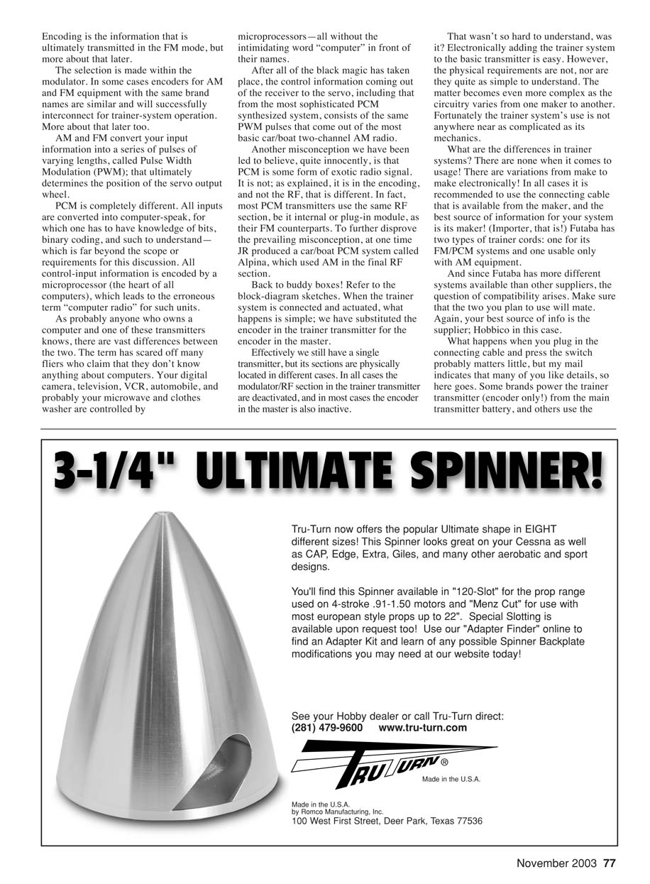
As sophisticated and functional as some modern transmitters are, they all break down into three basic sections: an encoder, a modulator, and a radio-frequency (RF) generator.
In given brands of radios, the modulator and RF sections are often similar. The encoder is what determines whether the transmitter is a basic 1970s-style four-channel unit or one that includes all of the requirements to fly all three basic model types—fixed-wing powered and sailplanes, and helicopters—in world-class competition. The encoder is where it all begins. Your inputs on the sticks, knobs, and switches are transformed into electronic information within the encoder circuitry. The encoder's output is then fed into and processed by the modulator, which, in turn, feeds your commands to the RF section for transmission into what in non-RC communications is referred to as the "ether": a hypothetical medium in which RF travels.
AM, FM, and PCM
Somewhat off of the buddy-box subject, I want to touch briefly on the common RC systems: Amplitude Modulation (AM), Frequency Modulation (FM), and Pulse Code Modulation (PCM). Some confusion exists: AM and FM are actual RF signals, but PCM is not.
Encoding is the information that is ultimately transmitted in the FM mode, but more about that later. The selection is made within the modulator. In some cases encoders for AM and FM equipment with the same brand names are similar and will successfully interconnect for trainer-system operation.
AM and FM convert your input information into a series of pulses of varying lengths, called Pulse Width Modulation (PWM); that ultimately determines the position of the servo output wheel.
PCM is completely different. All inputs are converted into computer-speak, for which one has to have knowledge of bits, binary coding, and such to understand—which is far beyond the scope or requirements for this discussion. All control-input information is encoded by a microprocessor (the heart of all computers), which leads to the erroneous term "computer radio" for such units.
As probably anyone who owns a computer and one of these transmitters knows, there are vast differences between the two. The term has scared off many fliers who claim that they don't know anything about computers. Your digital camera, television, VCR, automobile, and probably your microwave and clothes washer are controlled by microprocessors—all without the intimidating word "computer" in front of their names.
After all of the black magic has taken place, the control information coming out of the receiver to the servo, including that from the most sophisticated PCM synthesized system, consists of the same PWM pulses that come out of the most basic car/boat two-channel AM radio.
Another misconception we have been led to believe, quite innocently, is that PCM is some form of exotic radio signal. It is not; as explained, it is in the encoding, and not the RF, that is different. In fact, most PCM transmitters use the same RF section, be it internal or plug-in module, as their FM counterparts. To further disprove the prevailing misconception, at one time JR produced a car/boat PCM system called Alpina, which used AM in the final RF section.
How Trainer Systems Work
Back to buddy boxes! Refer to the block-diagram sketches. When the trainer system is connected and actuated, what happens is simple: we have substituted the encoder in the trainer transmitter for the encoder in the master.
Effectively we still have a single transmitter, but its sections are physically located in different cases. In all cases the modulator/RF section in the trainer transmitter is deactivated, and in most cases the encoder in the master is also inactive.
That wasn't so hard to understand, was it? Electronically adding the trainer system to the basic transmitter is easy. However, the physical requirements are not, nor are they quite as simple to understand. The matter becomes even more complex as the circuitry varies from one maker to another. Fortunately the trainer system's use is not anywhere near as complicated as its mechanics.
What are the differences in trainer systems? There are none when it comes to usage! There are variations from make to make electronically. In all cases it is recommended to use the connecting cable that is available from the maker, and the best source of information for your system is its maker (importer, that is). Futaba has two types of trainer cords: one for its FM/PCM systems and one usable only with AM equipment.
And since Futaba has more different systems available than other suppliers, the question of compatibility arises. Make sure that the two you plan to use will mate. Again, your best source of info is the supplier; Hobbico in this case.
When you plug in the connecting cable and press the switch, different things may happen depending on brand and model. Some brands power the trainer transmitter (encoder only!) from the main transmitter battery; others use the trainer transmitter's own battery.
Another potential issue is servo centering and signal compatibility: each transmitter may indicate normal operation when checked with its own servos, but problems can appear when matching different brands. One of the service centers might help, but in all cases curing a problem that only shows up in flight is impossible to duplicate on the test bench and difficult to cure.
I have not tried it, but it is generally accepted that Futaba and Hitec transmitters work with each other as master/trainer or vice versa. Even with two same-name transmitters, a good range check using the master and trainer should be made; it is doubly important in the case of a mismatch of brands such as this.
As I mentioned, not all same-brand transmitters mate with all others of that brand in the trainer mode; it is important to find out which will. Some of the makers sell trainer-only transmitters (without modulator and RF sections) for this use at affordable prices.
If you see yourself having a continuing use for this method of RC flight training, it may be worthwhile to find out from the maker of yours whether or not such a unit is available. In any case, whatever you use to teach or learn RC flight, now you have more of an idea of what is going on!
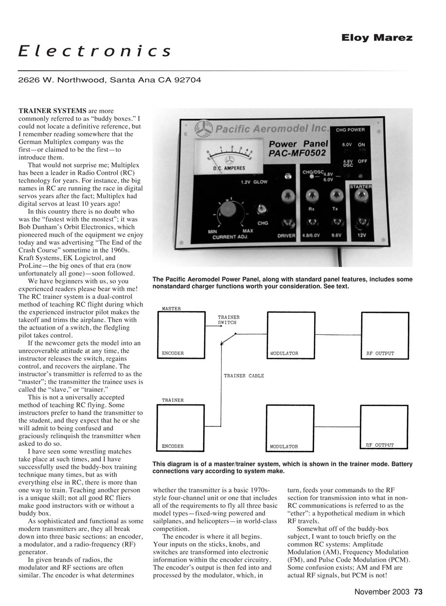
Pacific Aeromodel Power Panel
Pacific Aeromodel (PA) has recently introduced a power panel worth considering. The company is better known for its high-quality Scale Almost Ready-to-Fly airplanes, but this panel has capabilities that stand out.
The PA panel has the usual straight-through connections for your engine starter, through which you can also charge the supply battery. Although it's not stated in the instructions, the same 12-volt output could also be used to power an electric fuel pump.
The glow-plug supply is adjustable and metered. The instructions remind you that different glow plugs have different power requirements and caution you to start with the low settings. Once you have obtained the correct setting for a specific plug, you can correctly duplicate it with the meter.
Not common to all power panels are the battery-charging features on the PA unit. It will charge your glow-plug starter battery, which plugs directly onto a glow-plug-like fitting. The charge level is controlled by the current-adjusting knob, and it should be set to avoid overheating the battery being charged.
You can also charge or peak your transmitter and receiver batteries—four- or five-cell in the former, five- or six-cell in the latter. The transmitter-charge section is nonautomatic; according to my tests, that will revive the battery starting at some 250 milliamperes, slowly decreasing, all depending on its charge condition. The instructions recommend a maximum five-hour charge period.
The receiver-battery charger is more sophisticated and is switch-selectable for five or six cells. It includes a 160-milliamp discharge feature so you can start fresh if you like.
Discharge/charge status is indicated by light-emitting diodes. This is a peak-detect charger which charges normally at roughly 750 milliamps, after which it automatically drops to a 10-milliamp trickle rate.
- Standard straight-through starter/charging connections
- 12-volt output (can be used for an electric fuel pump)
- Adjustable, metered glow-plug supply
- Glow-plug starter battery charging with current adjustment
- Transmitter charger (nonautomatic), recommended max 5-hour charge
- Receiver charger: selectable for 5 or 6 cells, with 160 mA discharge
- Peak-detect charger: ~750 mA charge, then 10 mA trickle
- Discharge/charge indicated by LEDs
The PA power panel has become the standard size for the units, and the suggested price is $44.95. The street price is undoubtedly less; check around.
Contact Pacific Aeromodel Mfg. Inc. 15437 Proctor Ave., City of Industry, CA 91745 Tel.: (626) 961-6199 Web site: www.pacaeromodel.com
Transcribed from original scans by AI. Minor OCR errors may remain.

