
Electronics
Eloy Marez 2626 W. Northwood, Santa Ana CA 92704
Servos again
SERVOS AGAIN! Or still! My previous efforts on the subject are still generating mail. I want to share one piece with you because it raises a popular misconception. It comes from a Dr. Goode of Westland, Michigan:
"Your article describing servo operation in the September issue of MA was very informative; however, current polarity for rotational control was barely mentioned. How does the stick movement on the transmitter translate rotational direction of the servo from the receiver? If the transmitter does not have a servo reversing switch, can the servo direction be changed simply by switching the positive and negative leads, leaving the signal wire intact? A [major importer] representative told me the feedback pot leads would also need to be switched. Is this true?"
If you try to reverse servo direction by reversing the positive and negative (usually red and black) leads at the servo plug, you will know something is wrong as soon as you plug it in; servos are not supposed to smoke like that! That is a common misconception, and I hear it often.
I will explain how to reverse a servo correctly, but first I'll take a closer look at what actually happens to command a servo in the opposite direction. True, it is done by reversing the voltage to the motor, but it is done electronically, by the servo amplifier—not at the servo plug. The motor voltage polarity is determined by whether the input signal is shorter or longer than the nominal 1.5 milliseconds that commands servo centering. The process was explained in the September 1999 column.
What happens at the transmitter
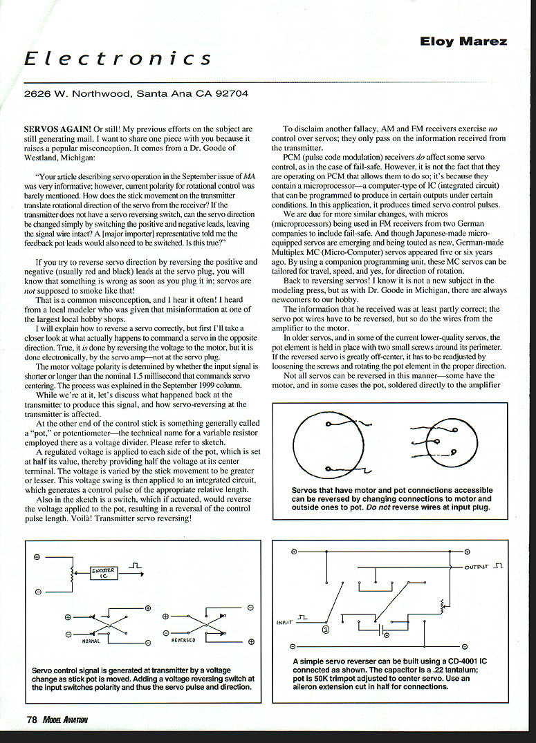
At the other end of the control stick is something generally called a "pot," or potentiometer—the technical name for a variable resistor employed there as a voltage divider. A regulated voltage is applied to each side of the pot, which is set at half its value, thereby providing half the voltage at its center terminal. The voltage is varied by the stick movement to be greater or lesser. This voltage swing is then applied to an integrated circuit, which generates a control pulse of the appropriate relative length.
A switch in the transmitter, if actuated, will reverse the voltage applied to the pot, resulting in a reversal of the control pulse length. Voila! Transmitter servo reversing.
Receivers and PCM
To disclaim another fallacy, AM and FM receivers exercise no control over servos; they only pass on the information received from the transmitter.
PCM (pulse code modulation) receivers do affect some servo control, as in the case of fail-safe. However, it is not the fact that they are operating on PCM that allows them to do so; it is because they contain a microprocessor—a computer-type integrated circuit that can be programmed to produce certain outputs under certain conditions. In this application, it produces timed servo control pulses.
We are due for more similar changes, with microprocessors being used in FM receivers from some companies to induce fail-safe. And though Japanese-made micro-equipped servos are emerging and being touted as new, German-made Multiplex MC (Micro-Computer) servos appeared five or six years ago. By using a companion programming unit, these MC servos can be tailored for travel, speed, and, yes, direction of rotation.
How to reverse a servo
Back to reversing servos! The information Dr. Goode received was partly correct: the servo pot wires have to be reversed, but so do the wires from the amplifier to the motor. In older servos, and in some current lower-quality servos, the pot element is held in place with two small screws around its perimeter. If the reversed servo is greatly off-center, it has to be readjusted by loosening the screws and rotating the pot element in the proper direction.
Not all servos can be reversed in this manner—some have the motor, and in some cases the pot, soldered directly to the amplifier board without any wires. You will know as soon as you remove the servo's bottom cover.
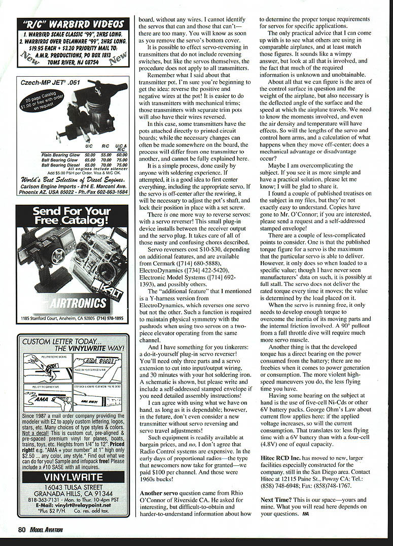
Servos that have motor and pot connections accessible can be reversed by changing connections to the motor (swap the motor leads) and the outer two leads of the pot. Do not reverse wires at the input plug.
It is possible to effect servo-reversing on transmitters that do not include reversing switches, but like the servos themselves, the procedure does not apply to all transmitters. Remember the transmitter pot: reverse the positive and negative wires at the pot. This is easier on transmitters with mechanical trims; those with separate trim pots will also have their wires reversed. On some transmitters the pots are attached directly to printed circuit boards; while changes can sometimes be made on the board, the process will differ from one transmitter to another and cannot be fully explained here.
If you attempt transmitter rewiring, center everything first—including the appropriate servo. If the servo is off-center after the rewiring, adjust the pot's shaft and lock its position with a set screw. This is a simple process for anyone with soldering experience.
Servo reverser devices and DIY option
There is one more way to reverse servos: with a servo reverser. This small plug-in device installs between the receiver output and the servo plug and handles the reversing. Servo reversers cost about $10–$30, depending on features, and are available from several suppliers.
An "additional feature" in some reversers is a Y-harness version that reverses one servo but not the other. Such a function is useful to maintain physical symmetry with the pushrods when using two servos on a two-piece elevator operating from the same channel.
For tinkerers: a do-it-yourself plug-in servo reverser can be built with only three parts and a servo extension to cut into input/output wiring, and about 30 minutes with a soldering iron. A schematic is available; write with a self-addressed stamped envelope if you need detailed assembly instructions.
I can agree with using what we have on hand, as long as it is dependable; however, in the future, don't even consider a new transmitter without servo reversing and servo travel adjustments! Such equipment is readily available at bargain prices.
Torque and servo selection
Another servo question came from Rhio O'Connor of Riverside, CA. He asked for information about how to determine the proper torque requirements for servos for specific applications.
The only practical advice I can come up with is to see what others are using in comparable airplanes, and at least match those figures. It sounds like a wimpy answer, but look at all that is involved, and the fact that much of the required information is unknown and unobtainable.
About all we can figure out easily is the area of the control surface and the weight of the airplane, but also necessary are the deflected angle of the surface and the speed at which the airplane travels. We need to know the moments involved; even air density and temperature will have effects. So will the lengths of the servo and control horn arms, and what happens when they move off-center—does a mechanical advantage or disadvantage occur?
There are a couple of less-complicated points to consider:
- The published torque figure for a servo is the maximum the servo is capable of delivering. However, it only does so under a specific load (possibly at full stall). The servo does not deliver the rated torque every time it moves; the value is determined by the applied load.
- When the servo runs free, it only needs to overcome the inertia of its moving parts and internal friction. A 90° pullout from a full-throttle dive will require much more torque.
- The developed torque has a direct bearing on power consumed from the battery. The more violent high-speed maneuvers you do, the less flying time you have.
- Using a higher applied voltage (for example, five-cell NiCd or other 6V packs) increases current consumption (Ohm's Law). That translates to less flying time with a 6V battery than with a 4.8V (four-cell) pack of equal capacity.
If you have a practical solution for calculating required torque, please let me know; I'm glad to share it. I found a couple of published treatises on the subject, but they're not easy to understand. Copies have gone to Mr. O'Connor; if you are interested, send a request and a self-addressed stamped envelope.
Notes and contacts
Hitec RCD Inc. has moved to new, larger facilities in the San Diego area. Contact Hitec at: 12115 Paine St., Poway, CA; Tel: (858) 748-6948; Fax: (858) 748-1767.
Servo reverser suppliers mentioned:
- Cermark: (714) 680-5888
- ElectroDynamics: (734) 422-5420
- Electronic Model Systems: (714) 692-1393
Next time?
This is our space—yours and mine. What you will read here depends on your questions. MA
Transcribed from original scans by AI. Minor OCR errors may remain.

