

Electronics
Eloy Marez
EUROPEAN Component Values You might notice how things happen coincidentally. That just occurred here. I got interested in a schematic diagram and had a telephone call about some of the different component markings it used.
Instead of the usual 4.7K (4,700 ohms or 4.7 kilohms) or 4.7M (4,700,000 ohms or 4.7 megohms), we saw 4K7 and 4M7. That is the European way of stating resistance values.
Now that it has been brought to my attention, I see it more and more. Maybe this system is slowly creeping into our technology. I like metrics; the European system uses the letter where a decimal should be. The letter indicates the multiplier. And no, you don't have to use a European resistor to make a so-labeled circuit work. A normal American resistor—or a Japanese resistor, as is often the case—of the proper value will do!
A similar identification system is used for stating the value of capacitors. This system uses "nanofarad" (1,000 picofarads), generally written as "nF" or "n."
A common 10,000 pF capacitor—most often written as .01 microfarad (µF)—may show up in European schematics as 10 nF or 10n.
None of this is intended to further complicate an already complicated subject; it's just that we are not all synchronized yet. Did you know that over there, you are a "modeller," not a "modeler"?
Component Testing Once you are able to read codes—US or European—the next step in troubleshooting a piece of suspect equipment is to test the component for its supposed value.
Resistors
- Testing resistors is cut-and-dried. Use an ohmmeter set to a range that includes the value you are trying to read, and place the meter's probes across the unit.
- This works well for out-of-circuit resistors; the value read across a resistor installed in a circuit depends on other circuit components, and the value indicated by its color code is seldom read as expected.
- The only acceptable check for an in-circuit resistor is to compare the indicated value to the value of the same resistor in similar equipment that is operating normally.
Capacitors
- Testing capacitors is not so simple. Capacitor testers are available, but they tend to be expensive and most of us learn to live without them.
- You can do an ohmmeter test for shorted capacitors, but that's about all. Like any other component, testing by replacement is also an option.
Diodes and Transistors I will discuss diodes and transistors together, because they share some characteristics. They are also the subject of testing techniques that require specialized equipment. But there are simple go/no-go tests to confirm even partial failures, and they require nothing more than a common digital or analog multimeter.
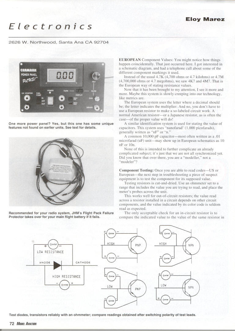
Diodes
- A diode is basically nothing more than a one-way valve, allowing electron flow in one direction, but not in the other.
- There are numerous types of diodes for specific functions, but I will address only the most common ones: the silicon diode and a close cousin, the rectifier diode. The rectifier diode can handle greater currents and is primarily used to rectify alternating to direct current.
- A diode has two parts: an anode and a cathode, which are respectively represented by an arrow and a bar. The polarity of a voltage applied to a diode will determine whether or not it will conduct.
- Since a low voltage is present at the probes of an ohmmeter, that will be the voltage in the testing procedure. If the positive meter probe is applied to the anode (arrow) and the negative probe is applied to the cathode (bar), current will flow and the ohmmeter will indicate a low resistance. With the probes reversed (positive to cathode, negative to anode), little current will flow and the meter will indicate a high resistance.
- A meter reading a low resistance in both cases indicates a shorted diode. A high resistance points to one that is open (burned out).
Transistors
- The transistor is a more-complicated device than the diode, with many more uses. It can be a switch, an oscillator, an amplifier, etc. There are several types of transistors, and the most common is the bipolar silicon type.
- Bipolar silicon transistors come in two types: PNP and NPN, referring to the internal composition and the polarity of the applied voltage.
- The elements of a transistor are the base (B), the collector (C), and the emitter (E). For test purposes, consider the transistor as back-to-back diodes, with the base being the common point. Then you can test them with an ohmmeter in the same manner as diodes, looking for a high-low resistance change using the meter polarity.
- Equal low resistance readings are indicative of a short in the element, and equal high readings point to one that has failed. Although this is not a test of all the characteristics of a transistor, it will generally isolate defective ones for you.
- It is an excellent test for out-of-circuit transistors, but as in the case of the diode, it can give unreliable readings if tested in a circuit. If possible, desoldering the base lead from the circuit will result in a more dependable test. Also, a comparison reading in a working device will yield reliable information.
Reader Mail and Clarification Phone calls—mostly comments and mostly positive.
M. O'Neill in Placentia, California wrote: "The article in whole was great, and I hope to get it into club newsletters. There was one statement that is either a typo or incomplete on page 84. Should the receiver battery totally fail, one would have a total HOLD mode, but the typical receiver failure if one cell shorted, which in my Futaba PCM chops the throttle, which is operable again to land pronto by doing a minimum throttle and then advancing it. This has saved my butt at least twice. Yes, you can check the receiver battery before each flight, but it could die with no warning. I think this is worth a clarification in your future article."
In case of a complete battery failure (more likely a disconnect or a broken switch or wire, but still a complete loss of battery power), the airborne system will be in a sort of HOLD mode, with all servos at their last position.
However, the hold will not be caused by a PCM hold, which requires battery power to operate. The hold will be in place because everything is dead, just as if you had turned off the switch.
In case of a shorted cell—as Mr. O'Neill states—or a more-likely low-capacity cell (which will drop the pack voltage by one cell), the useful Battery Fail Safe (BFS) function will go into effect.
You PCM radio users should remember that if your engine suddenly runs at less than full snarl, it may not be an engine malfunction; your radio may have gone into BFS. Cycle the throttle stick to idle position, then up again. If the engine responds normally, it is time to land—as M. O'Neill says—"pronto."
Batteries At this writing, Great Planes Model Distributors has been Futaba's exclusive US importer for only a few months, and has not had time to make any changes.
I have no way of knowing if any changes are planned, but Great Planes has many hands-on, active modelers on its staff, and I hope they will be listened to.
Maybe there will be some changes in the batteries that Futaba has used for the past few years—an unbranded plain-brown-wrapper type that has made many users uncomfortable. Some Futaba filers' first action with a new radio is to retire the unknown batteries to their kids' radio-controlled cars, and install fresh, new Sanyo cells.
Redundancy I am all for it. I could easily live with larger and heavier airborne equipment that recognizes failures, and automatically switches in the backup circuitry, as does the equipment used in commercial and military electronics.
We want it small and we get it small, but with no built-in safety features. One of the weak points is batteries. They are much better than in earlier Radio Control years, but they still fail.
Luckily, there is some redundancy in this respect; JHM Aero Engineering has released the Flight Pack Failure Protector.
Flight Pack Failure Protector
- The Flight Pack Failure Protector's primary purpose is to come into action if the primary airborne battery fails; otherwise, it just goes along for the ride.
- If the primary airborne battery fails in any way, for any reason, the unit switches in a fresh one. When the protector goes into action, an LED (light-emitting diode) indicates that the system is on the backup battery.
- This system is even better than BFS—especially under competition conditions, during which an unplanned landing is going to earn you zero points.
- JHM's Flight Pack Failure Protector is a complete system. It comes with the necessary electronics and an 800 mAh Sanyo battery—all in one unit that's slightly larger than the battery itself. The system's dimensions are 1 2 x 2.25 inches, and it weighs 4.7 ounces.
- All you have to do is charge it and plug it in, just as you would with any other battery. No adjustments or tuning are required, and the unit is compatible with all types of radio systems.
- The protector comes sealed and is described as being all solid state; it uses Complementary Metal Oxide Semiconductor (CMOS) and Metal Oxide Semiconductor Field Effect Transistor (MOSFET) voltage measuring and switching technology.
- The Flight Pack Protector is available for use with 4.8-volt (four-cell) or 6.0-volt (five-cell) packs. The two are not interchangeable. The unit can be ordered with wiring for all the popular radio systems, including Airtronics' new Z Connectors.
- The system is available with your choice of a case-mounted or remote 12-inch LED lead.
Ordering and Guarantee
- The Flight Pack Failure Protector is available directly from JHM Aero Engineering.
- Cost is $49 for the 4.8-volt unit and $51 for the 6.0-volt unit. Add $4 for shipping.
- The guarantee period is one year; during that time, even the battery will be replaced if it goes bad for any reason.
Contact JHM Aero Engineering 123 Radford Cr., Marietta GA 30060 Tel.: (770) 438-7146 Fax: (770) 438-9654 Web site: www.jhmaeroengineering.com
MA
Transcribed from original scans by AI. Minor OCR errors may remain.

