
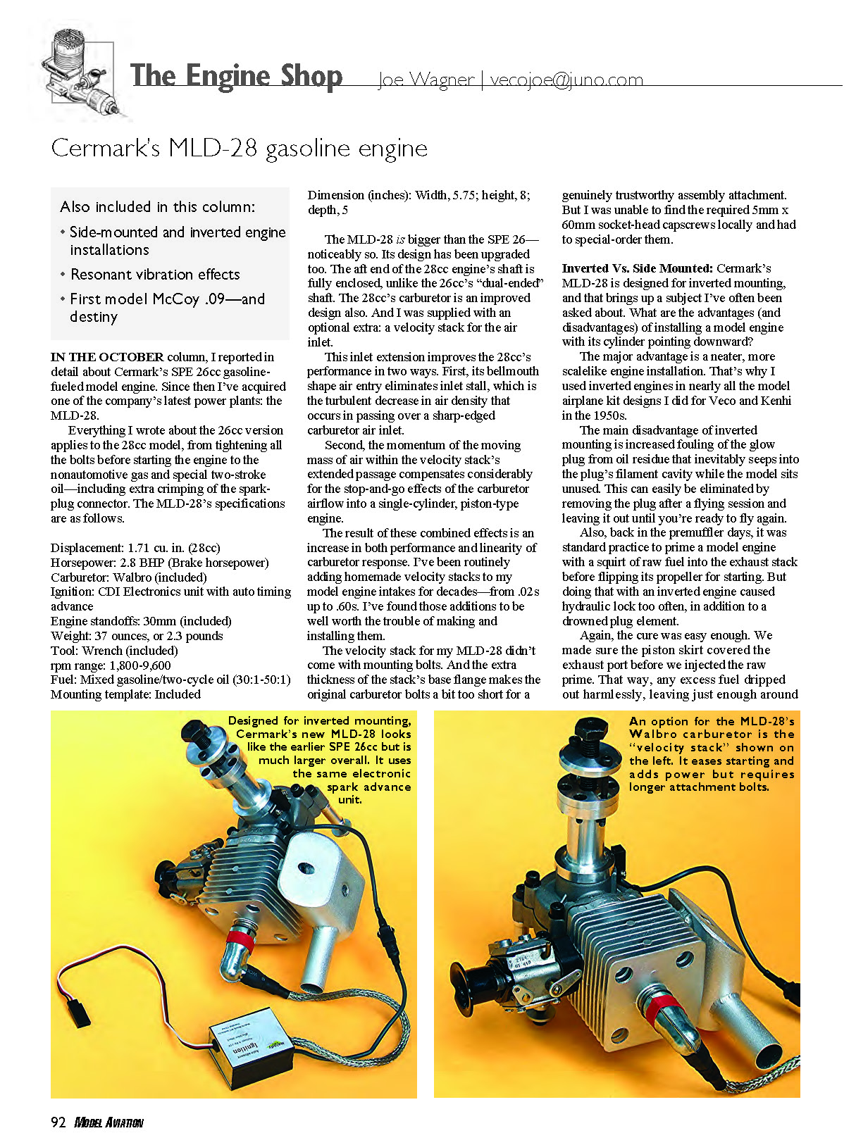

The Engine Shop
Cermark's MLD-28 gasoline engine
In the October column, I reported in detail about Cermark's SPE 26cc gasoline-fueled model engine. Since then I've acquired one of the company's latest powerplants: the MLD-28.
Everything I wrote about the 26cc version applies to the 28cc model, from tightening all the bolts before starting the engine to the nonautomotive gas and special two-stroke oil — including extra crimping of the spark-plug connector. The MLD-28's specifications are as follows.
- Displacement: 1.71 cu. in. (28cc)
- Horsepower: 2.8 BHP (Brake horsepower)
- Carburetor: Walbro (included)
- Ignition: CDI Electronics unit with auto timing advance
- Engine standoffs: 30 mm (included)
- Weight: 37 ounces (2.3 pounds)
- Tool: Wrench (included)
- RPM range: 1,800–9,600
- Fuel: Mixed gasoline/two-cycle oil (30:1–50:1)
- Mounting template: Included
- Dimensions (inches): Width 5.75; height 8; depth 5
The MLD-28 is bigger than the SPE 26 — noticeably so. Its design has been upgraded too. The aft end of the 28cc engine's shaft is fully enclosed, unlike the 26cc's "dual-ended" shaft. The 28cc's carburetor is an improved design also. And I was supplied with an optional extra: a velocity stack for the air inlet.
This inlet extension improves the 28cc's performance in two ways. First, its bellmouth-shaped air entry eliminates inlet stall, which is the turbulent decrease in air density that occurs when air passes over a sharp-edged carburetor air inlet.
Second, the momentum of the moving mass of air within the velocity stack's extended passage compensates considerably for the stop-and-go effects of the carburetor airflow into a single-cylinder, piston-type engine.
The result of these combined effects is an increase in both performance and linearity of carburetor response. I've been routinely adding homemade velocity stacks to my model engine intakes for decades — from .020s up to .60s. I've found those additions to be well worth the trouble of making and installing them.
The velocity stack for my MLD-28 didn't come with mounting bolts. And the extra thickness of the stack's base flange makes the original carburetor bolts a bit too short for a genuinely trustworthy assembly attachment. I was unable to find the required 5 mm x 60 mm socket-head capscrews locally and had to special-order them.
Inverted Vs. Side Mounted
Cermark's MLD-28 is designed for inverted mounting, and that brings up a subject I've often been asked about. What are the advantages (and disadvantages) of installing a model engine with its cylinder pointing downward?
The major advantage is a neater, more scale-like engine installation. That's why I used inverted engines in nearly all the model airplane kit designs I did for Veco and Kenhi in the 1950s.
The main disadvantage of inverted mounting is increased fouling of the glow plug from oil residue that inevitably seeps into the plug's filament cavity while the model sits unused. This can easily be eliminated by removing the plug after a flying session and leaving it out until you're ready to fly again.
Also, back in the premuffler days, it was standard practice to prime a model engine with a squirt of raw fuel into the exhaust stack before flipping its propeller for starting. But doing that with an inverted engine caused hydraulic lock too often, in addition to a drowned plug element.
The cure was simple. We made sure the piston skirt covered the exhaust port before we injected the raw prime. That way, any excess fuel dripped out harmlessly, leaving just enough around the edge of the port for an easy startup.
Another engine-mounting setup—sideways—offers advantages without disadvantages. With its exhaust pointing downward, flooding is never a problem during startup.
That is especially true with diesel-powered models. With the exhaust opening downward, excess fuel from choking can escape easily, eliminating hydraulic lock and flooding. Those are the two most common reasons for difficulty in diesel starting.
Vibration Sources
Robert Kuehne (Otisville, Pennsylvania) wrote to me recently about a severe vibration problem he thought was caused by his engine.
"At about half throttle the engine vibrates very severely and usually cuts out," he wrote. "At idle it runs nicely, but when I try going back to full throttle it vibrates badly at half throttle again."
I wrote back to Robert, telling him that although the source of his serious vibration problem seemed to be the engine, its severity was really caused by resonance.
I had seen this happen fairly often back in the Good Old Days, as a model flier advanced the spark on one of the ignition engines all of us gas-power modelers used then. Many times, when the engine RPM reached a certain point, the entire airplane would shake violently. We soon learned to pass quickly through that RPM range, which was the only speed at which serious vibration occurred.
This trouble arises because every structure has its natural vibration frequency. That's why marching troops "break step" when crossing a bridge: to avoid the slightest chance of the simultaneous impacts of their feet on the bridge's roadway matching the bridge structure's natural frequency and causing a catastrophic collapse. Yes, that has happened.
It's impossible to achieve dynamic balance in any single-cylinder engine. You cannot balance out the reciprocating mass of its piston with counterbalancing on the rotating crankshaft. Whatever reduction in the piston's up-and-down vibration a counterbalance on the crank web may provide is translated into an equal side-to-side vibration.
Because of geometric principles, counterbalancing half the mass of the reciprocating parts results in roughly a 30% reduction in total dynamic imbalance effect. That's nearly the best that can be expected. But that doesn't affect resonance!
Resonant effects appear the strongest in lightweight, built-up model structures. Free-flight airplanes with high-powered, fast-revving engines seem most sensitive to those.
At a US Free Flight Championships meet at Lost Hills, California, a few years ago, I saw a half-dozen power models demolish themselves in the climb. Everyone looked up at them as they blew apart—alerted by the unmistakable, loud, scary sound of the resonating structure just before it destroyed itself.
(Editor's note: Proving Joe's point that the effect is common, we have tested smooth electric outrunner-powered models, and they also experience airframe resonance noise. The sound that is produced is alarming.)
What can be done to avoid this evil condition—especially in RC models, where engine RPM can vary so greatly in flight? Soft-mounting the engine provides a useful fix, but side mounting works just as well. That's because it changes the major vibratory input's direction from vertical to transverse, where structural resonance is much lower and far less powerful.
The Rest of the Story
In 1948, the makers of the then-famous McCoy Redhead racing engines made a deal with the Veco model airplane kit manufacturers to collaborate on a major project to promote CL flying among America’s youth. The plan was for McCoy to provide a small engine (an .09; the 1/2A hadn’t been invented yet), and Veco would design a small CL model specifically for that power plant. Then both companies would mass-produce and aggressively market the products.
Veco fulfilled its part of the agreement by designing a 30-inch-span airplane called the Papoose and cutting parts for 10,000 kits. But McCoy’s little .09 proved to be a dud. The first ones had no glow plugs—merely a replaceable filament installed beneath the head casting that didn’t work reliably. A glow plug was tried next. It performed a little better, but not well enough.
Months of further modifications failed to come up with the easy-starting, simple-to-adjust small engine that the McCoy-Veco “Papoose Project” required. That failure doomed the venture and left Veco holding the bag, with balsa, hardware packs, precut Silkspan, formed landing-gear wires, and boxes for those 10,000 Papoose kits—a design in which no other engine would fit.
Veco was only roughly a year old at the time and in no position to absorb the financial loss of scrapping the entire costly but unusable Papoose inventory. Then I came by looking for a job.
I talked with Howard “Hi” Johnson (Veco’s chief engineer), whom I had met earlier at a trade show in San Francisco, California. Hi said he wanted to hire me, but the company was in trouble because of the McCoy .09/Papoose fiasco and couldn’t afford me.
“We’ve got too much money tied up in all that Papoose stuff,” he said.
I was about to shake Hi’s hand in farewell when a thought occurred to me: “What if I designed some models for you that would use up the Papoose materials?”
The result was that Veco hired me—not as a designer but as a wood-shop worker. After hours, I designed, built, and tested two 1/2A free-flight models that later became classics: the Dakota all-sheet-balsa biplane and the Sioux monoplane. Together the kits made use of more than 80% of the Papoose’s materials. The only things we had to scrap were the Papoose plans and die-cut sheetwood.
That was my start in the model industry. I got my wife when she started work at Veco—got involved in model-engine making and testing with Veco’s first products in that line. But if McCoy’s original Redhead .09 had been successful, none of that would have happened—and I wouldn’t be writing this column now.
MA
Sources
- Cermark
- (800) 704-6229
- www.cermark.com
Transcribed from original scans by AI. Minor OCR errors may remain.

