
The Engine Shop
927 Pine Ave., Ozark AL 36360
Miscellany Month: SMALLnet
If you enjoy flying model airplanes powered with engines less than .26 cubic-inches displacement, the SMALLnet online forum should interest you.
SMALLnet is a free "newsletter" containing much operational and troubleshooting information on small-sized glow and diesel engines. (There's a good bit of CO2 and compressed-air-power data as well.)
To join, send an E-mail to [email protected] and type the word "subscribe" in the "Subject" line. That's all there is to it!
There have been more than 300 SMALLnet postings so far, and copies of all previous postings are available on the SMALLnet Web site. They contain scads of useful tips from such well-known model-engine men as George Aldrich, Ed Stevens (the Norvel man), Larry Renger (former chief engineer at Cox), Eric Clutton ("Dr. Diesel"), Dave Larkin (Canada's top model diesel expert), and myself.
Increasing oil content in glow fuel
A subject that's been mentioned more than once in past "The Engine Shop" columns is increasing the oil content of commercial glow fuel.
Many of us have found that we get better performance and longer life from our power plants when we run them exclusively on fuel with 20–25% lubricant content—most of that castor oil.
Several readers have asked how to go about bringing, say, a quart of 16%-oil fuel up to the 25% level. The method isn't difficult, especially with the help of an electronic calculator.
- A quart equals 32 fluid ounces (fl. oz.); 16% of that is close to 5 ounces—the oil content of the "stock blend."
- Suppose we add 4 fl. oz. of castor oil (available from Sig or PowerMaster). That brings the total volume up to 36 fl. oz., of which 9 fl. oz. is oil. Nine is exactly 25% of 36.
Of course, augmenting the oil content of glow fuel lowers the nitromethane percentage at the same time.
- If you start with 15% nitro fuel, it contains 4.8 fl. oz. of nitro per quart. Adding 4 fl. oz. of castor oil brings the total volume to 36 ounces, but there's still 4.8 fl. oz. of nitromethane in that 36 ounces, so the new nitro percentage drops to 13%.
Replacing evaporated ether in model diesel fuel
A major problem that model diesel fliers suffer from is ether evaporation from their fuel. Ether is one of the most volatile fluids in existence, and it swiftly vaporizes into the air each time we open a can of model diesel fuel.
Low ether content in fuel causes hard starting, hot running, and power loss in model diesels. But obtaining pure ether for replenishing model diesel fuel is expensive and hard to do in most of the U.S.
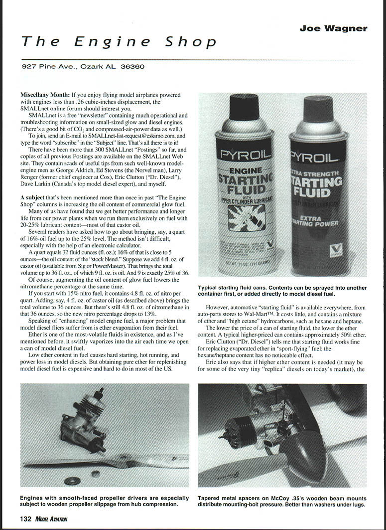
However, automotive "starting fluid" is available everywhere, from auto-parts stores to Wal-Mart. It costs little and contains a mixture of ether and "high cetane" hydrocarbons, such as hexane and heptane. The lower the price of a can of starting fluid, the lower the ether content. A typical higher-priced can contains approximately 50% ether.
Eric Clutton ("Dr. Diesel") tells me that starting fluid works fine for replacing evaporated ether in "sport-flying" fuel; the hexane/heptane content has no noticeable effect. Eric also says that if higher ether content is needed (it may be for some of the very tiny "replica" diesels on today's market), the John Deere brand of starting fluid contains 87% ether.
But Eric maintains that most of today's model diesel engines aren't finicky about exact ether content. If there's enough ether for easy starting (always by hand—never with an electric starter!), the precise percentage doesn't matter much. That agrees with my experience.
Wood compression problems
A seldom-discussed source of difficulty with model engines is wood compression.
I first encountered trouble from wood compression in the 1940s—a "funny sound" and reduced power output from my usually reliable Forster .29 sparker, installed in a Jim Walker Fireball control-line model. The trouble was the result of the wooden propeller hub gradually compressing under the constant pressure exerted by the prop nut and washer. (Of course I left the prop nut tight between flying sessions—doesn't everyone?) The hardwood propeller hub squeezed down just enough to allow it to slip slightly in operation. It wasn't much, but it made a noticeable difference in the sound of the engine and its ability to haul my Fireball around the circle.
Several times since then, I've seen "compression problems" with wooden and plain nylon propellers. Hot-running engines can conduct enough heat down their crankshafts to soften some types of plastic propellers and allow their hubs to compress. The usual result of that is a thrown prop. The obvious preventive measure is to check your prop nut's tightness before each flying session.
Wooden engine-mounting beams can also compress. In fact, this is a common problem with control-line models—particularly profile types. Sooner or later, the combination of high pressure exerted by the mounting bolts and the effects of engine vibration form a depression into even the hardest rock-maple engine bearer.
The resulting looseness can unscrew bolts, cause thrustline variations, and make for erratic performance. Twice I've even seen engines fly out of their airplanes from the effects of engine mount compression.
Most fliers cope with this problem by retightening their engine-mounting bolts regularly; however, there are other ways of fighting back.
- Face wooden engine bearers on both sides with 1/16" sheet aluminum. That spreads out the bolt pressure and eliminates local wood compression.
- Glue a piece of 1/4" sheet aluminum to a block of scrap wood, then disk-sand and file its surface to roughly a 3° uniform taper. Cut 3/8-inch wide strips from the tapered sheet metal to face the engine side of the wooden mounts. That provides anti-compression and thrust offset to help keep the control lines taut in flight.
- Use aluminum tubing spacers that extend all the way through the wooden engine-mounting area. Early on, I telescoped several sizes of K&S aluminum tubing together to achieve a total wall thickness of at least 3½. Thin cyanoacrylate glue between each one holds them together for cutting and filing operations. Now K&S sells thick-walled aluminum tubing that can be used as is. Well-stocked hardware stores also carry aluminum tubing "standoff" spacers that can sometimes be conveniently used in this application.
The engine-mounting hole locations must be accurately laid out on the nose of the assembled profile fuselage. Bore the holes on a drill press, to fit the tubing. Clamp the fuselage firmly for each hole; the bit may break through the wood on the inside edges. It's best to cut the four lengths of tubing slightly oversize so they can be filed smooth and flush with the wood after they are epoxied firmly in place. When the airplane is finished, its engine can be bolted in place without fear of it ever loosening because of surface compression of its mounting.
Fuel-tank clunks and fuel decomposition
In this column approximately three years ago, I mentioned the catalytic effect of brass fuel-tank clunks on the small quantity of glow fuel that remains in the tank after a flying session. The resulting chemical reaction produces acetic acid—a proven rust inducer.
Since that column was published, I've received confirmation from other modelers who opened their regularly flown radio-control models' fuel tanks and were greeted with the unmistakable vinegary odor of acetic acid.
Evidently, manufacturers of "clunk tanks" have run their own tests of this phenomenon. Sullivan and Du-Bro are now nickel-plating their tank clunks. That will save me the trouble of solder-tinning any more plain brass clunks.
Incidentally, I've asked two users of sintered bronze clunks—the porous kind that also serve as fuel filters—to check for acid formation in their model tanks. They did, and no fuel decomposition seems to occur with the bronze clunks.
Apparently, the zinc component of brass acts as a catalyst to convert glow fuel into acetic acid. (Bronze is an alloy of copper and tin.)
MA
Transcribed from original scans by AI. Minor OCR errors may remain.

