
The Engine Shop
Joe Wagner 212 S. Pine Ave., Ozark, AL 36360
Brodak .40
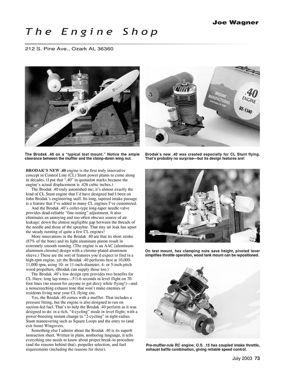
Brodak's new ".40" engine is the first truly innovative concept in Control Line (CL) Stunt power plants to come along in decades. (I put that ".40" in quotation marks because the engine's actual displacement is .426 cubic inches.)
The Brodak .40 truly astonished me; it's almost exactly the kind of CL Stunt engine I'd have designed had I been on John Brodak's engineering staff. Its long, tapered intake passage is a feature that I've added to many CL engines I've customized. The Brodak .40's collet-type long-taper needle valve provides dead-reliable fine-tuning adjustment and eliminates an annoying and too-often obscure source of air leakage: down the almost negligible gap between the threads of the needle and those of the spraybar. That tiny air leak has upset the steady running of quite a few CL engines.
Other notable features:
- Short stroke (87% of the bore) and a light aluminum piston contribute to extremely smooth running. The engine is an AAC design with a chrome-plated aluminum sleeve.
- Performs best at 10,000–11,000 rpm using 10- or 11-inch-diameter, 4- or 5-inch-pitch wood propellers. (Brodak can supply those too.)
- Low design rpm delivers long lap times—5½–6 seconds in level flight on 70-foot lines—and a nonscreeching exhaust tone that is less likely to annoy nearby residents.
- Includes a muffler with a pressure fitting; the engine is also designed to run on suction-fed fuel to allow rich "4-cycling" cruising and an instant change to "2-cycling" for tight-radius stunt maneuvers.
I also admire Brodak's superb instruction sheet. Written in plain, engaging language, it covers proper break-in procedure (and the reasons behind it), propeller selection, and fuel requirements (including the reasons for those).
Small accessories that help
Good things can come in small, plastic packages: Hobbico's After Run Oil and the Valvespout valve spout for model fueling are both very useful. I appreciate the Valvespout especially because in early January I helped some local modelers learn to operate their Christmas-gift RC engines (.10, .25, and .45 displacement), each of which required time-consuming modifications to one of my test mounts.
Test mounts, installation height, and fuel-tank positioning
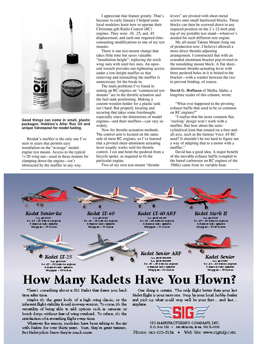
One test-mount change that takes little time but saves valuable "installation height" is replacing the stock wing nuts with steel hex nuts. An open-end wrench provides nut-tightening access under a low-height muffler so that removing and reinstalling the muffler is unnecessary for break-in.
The main problems I've found when setting up RC engines on commercial test mounts are throttle actuation and fuel-tank positioning. Making a custom wooden holder for a plastic tank isn't hard, but properly locating and securing it takes forethought, especially since engine and muffler dimensions vary widely.
Throttle-actuation methods
The control arm is located on the same side of most RC engines, so a pivoted sheet-aluminum actuating lever usually works well for throttle control. I cut and bend the pushrod from a bicycle spoke as required to fit the particular engine.
Two of my test-mount throttle levers are pivoted with sheet-metal screws onto small hardwood blocks. These blocks can then be screwed down in any required position on the 2 x 12-inch pine top of my portable test stand—whatever's needed for each different-size engine.
My all-metal Tatone Mount (long out of production) allowed a more direct throttle-adjusting arrangement. I constructed an extruded aluminum bracket pop-riveted to the nonsliding mount block. A flat sheet-aluminum throttle-actuating lever with three pushrod holes in it is bolted to the bracket, with a washer between the two to prevent binding.
Movable exhaust baffle — reader suggestion and alternatives
David G. Hoffman of Melba, Idaho, a longtime reader of this column, wrote:
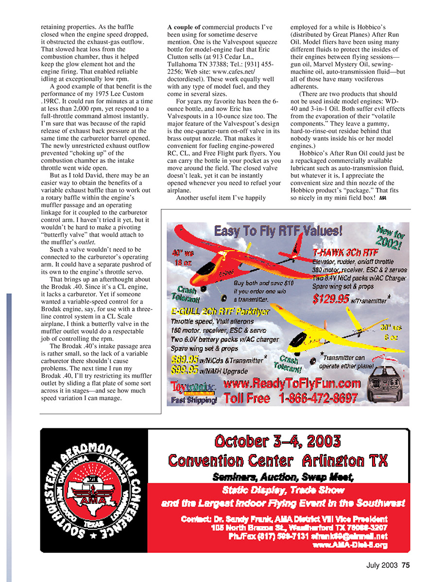
"Whatever happened to the pivoting exhaust baffle that used to be so common on RC engines? I realize that the more common flat, 'rocking' design won't work with a muffler. But how about the semi-cylindrical kind that rotated on a fore-and-aft axis, such as the famous Veco .45 RC used? It shouldn't be too hard to figure out a way of adapting that to a motor with a muffler."
David has a good idea. A major benefit of the movable exhaust baffle (coupled to the barrel carburetor on 1960s RC engines) came from its variable heat-retaining properties. As the baffle closed when engine speed dropped, it obstructed exhaust-gas outflow, slowing heat loss from the combustion chamber. That helped keep the glow element hot and the engine firing, enabling reliable idling at exceptionally low rpm.
A good example is my 1975 Lee Custom .19RC. It could run for minutes at less than 2,000 rpm yet respond almost instantly to full throttle. That performance was likely due to the rapid release of exhaust back pressure at the same time the carburetor barrel opened; the newly unrestricted exhaust outflow prevented "choking up" of the combustion chamber as the intake throttle went wide open.
As I told David, there may be an easier way to obtain the benefits of a variable exhaust baffle than creating a rotary baffle inside the muffler passage with an operating linkage to the carburetor control arm. I haven't tried it yet, but it wouldn't be hard to make a pivoting "butterfly valve" that attaches to the muffler outlet.
Such a valve wouldn't need to be linked to the carburetor. It could have a separate pushrod to the engine's throttle servo. That suggests an afterthought about the Brodak .40: since it's a CL engine, it lacks a carburetor, but if someone wanted variable-speed control (for example, for a three-line control system in a CL Scale airplane), a butterfly valve in the muffler outlet could provide respectable rpm control. The Brodak .40's intake passage area is rather small, so the lack of a variable carburetor there shouldn't cause problems. The next time I run my Brodak .40, I'll try restricting its muffler outlet by sliding a flat plate across it in stages to see how much speed variation I can manage.
Commercial products I recommend
- Valvespout squeeze bottles for model-engine fuel
- Sold by Eric Clutton, 913 Cedar Ln., Tullahoma, TN 37388; Tel.: (931) 455-2256; Web: www.cafes.net/doctordiesel.
- Come in several sizes (my favorite for years has been the 6-ounce bottle; a 10-ounce size is now available).
- Feature a one-quarter-turn on-off valve in the brass output nozzle, making fueling convenient and leak-free while carrying the bottle in your pocket at the field.
- Hobbico's After Run Oil (distributed by Great Planes)
- Many modelers have used gun oil, Marvel Mystery Oil, sewing-machine oil, or auto-transmission fluid to protect engines between flying sessions, but Hobbico's product is convenient in size and has a thin nozzle that fits nicely in a mini field box.
- Note: Do not use WD-40 or 3-in-1 Oil inside model engines. Their volatile components evaporate and leave a gummy, hard-to-rinse residue.
MA
Transcribed from original scans by AI. Minor OCR errors may remain.

